Guardian Telecom Inc.
Installation and Operation
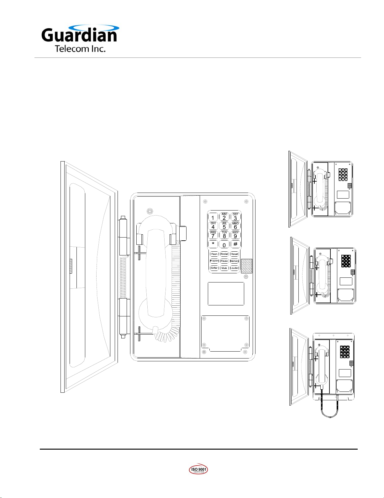
Model WRT
Page 7
Installing the WRT
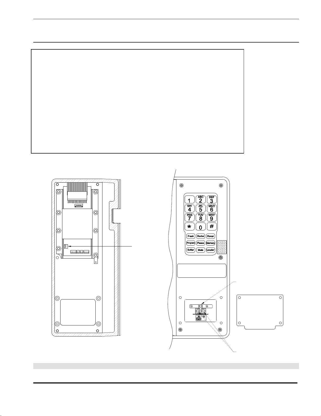
•The WRT is set to tone dialing when shipped. If pulse dialing is required
see the section on Setting Tone/Pulse Operation.
•Follow all appropriate electrical codes and use only approved electrical
fittings for the installation.
See: Figure 5 - Setting
Dialing Mode &
Installation
•Choose a wall location that is free of obstructions and permits space for
wiring.
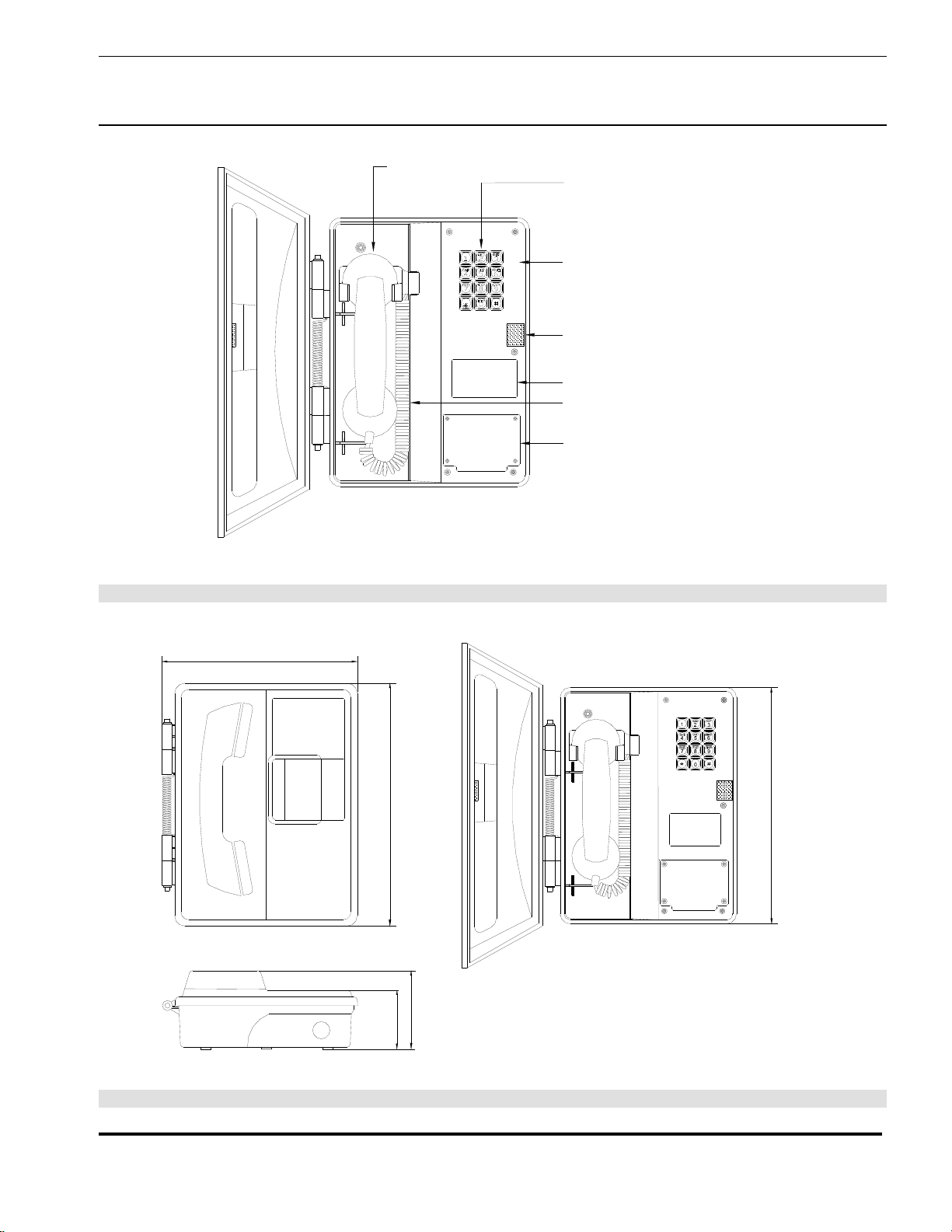
•Ensure mounting can support 6.5 lbs (2.95 kg) plus any additional,
foreseeable load.
See: Figure 2 - Overall
Dimensions - Standard
Models
•Ensure that none of the electrical connection circuits are live.
Mounting Without Optional Mounting Plate
•Use the appropriate template to locate and drill holes for mounting screws.
Use #10 or M5 screws to secure the unit to the wall. Use anchors in plaster
or cement to provide a firm grip for the mounting screws. Use sturdy hollow-
wall fasteners to mount the set to drywall.
•Loosen the five captive screws in the faceplate and swing the faceplate to
the left. If the set is on a vertical surface the faceplate will stay open like a
book in this position. Take care not to disturb the internal wiring.
See: Figure 2 - Overall
Dimensions - Standard
Models
•Secure the unit to the wall.
•Replace the faceplate. Do not over tighten the screws.
Mounting With Optional Mounting Plate
•Use the appropriate template to locate and drill holes for mounting screws.
•Secure the unit to the wall.
Wiring the WRT to the Telephone System
•Remove the wiring access cover plate.
•Bring cable into the enclosure through the conduit entrance and attach
individual wires from the exchange – Tip/Ring/Ground – to the surge
arrestor (Tip & Ring are not polarity sensitive). If a conduit hub is used,
ensure it is grounded to the ground stud.
•Replace the wiring access cover plate.
Final Check
•Check the set visually for loose screws and trapped wires. Check that the
handset hangs freely in the cradle and that the handset cord is not trapped
by the door.
•Check that the faceplate is snug to its gasket, paying particular attention to
the area around the cradle. Check that the door closes flush to the housing.
•Test the unit by calling to and from another unit on the exchange.