Guardian DTT-50 Manual

7552 - 10th Street N.E. Calgary, Alberta, Canada T2E 8W1
Industrial Communications Worldwide
DTT-50 & DTT-60 Telephones
Installation & Operation
P007117 Rev. B 110314 3/16/2011 1:11 PM
Ph: 403.258.3100 \ email:info@guardiantelecom.com \ www.guardiantelecom.com

Guardian Telecom Inc. Installation and Operation
DTT-50 & DTT-60 Telephones
Page 2
Table of Contents
Package Contents ........................................................................................2
Models..........................................................................................................2
Accessories ..................................................................................................2
Overview ......................................................................................................3
Features .......................................................................................................3
Installation ....................................................................................................6
Wiring ...........................................................................................................7
Retrofitting Headset/Supplemental Receiver, Strobe Light/Ringer...............8
Field Repairs & Adjustments ........................................................................9
Operating Modes and Software Features ..................................................11
Product Specifications................................................................................18
Replacement Parts.....................................................................................19
Warranty.....................................................................................................20
Disclaimer...................................................................................................20
Warning ......................................................................................................20
Service Telephone Number........................................................................20
Feedback....................................................................................................20
Guardian Product Return ...........................................................................21
Cleaning Tips for Guardian Telephones.....................................................22
Table of Figures
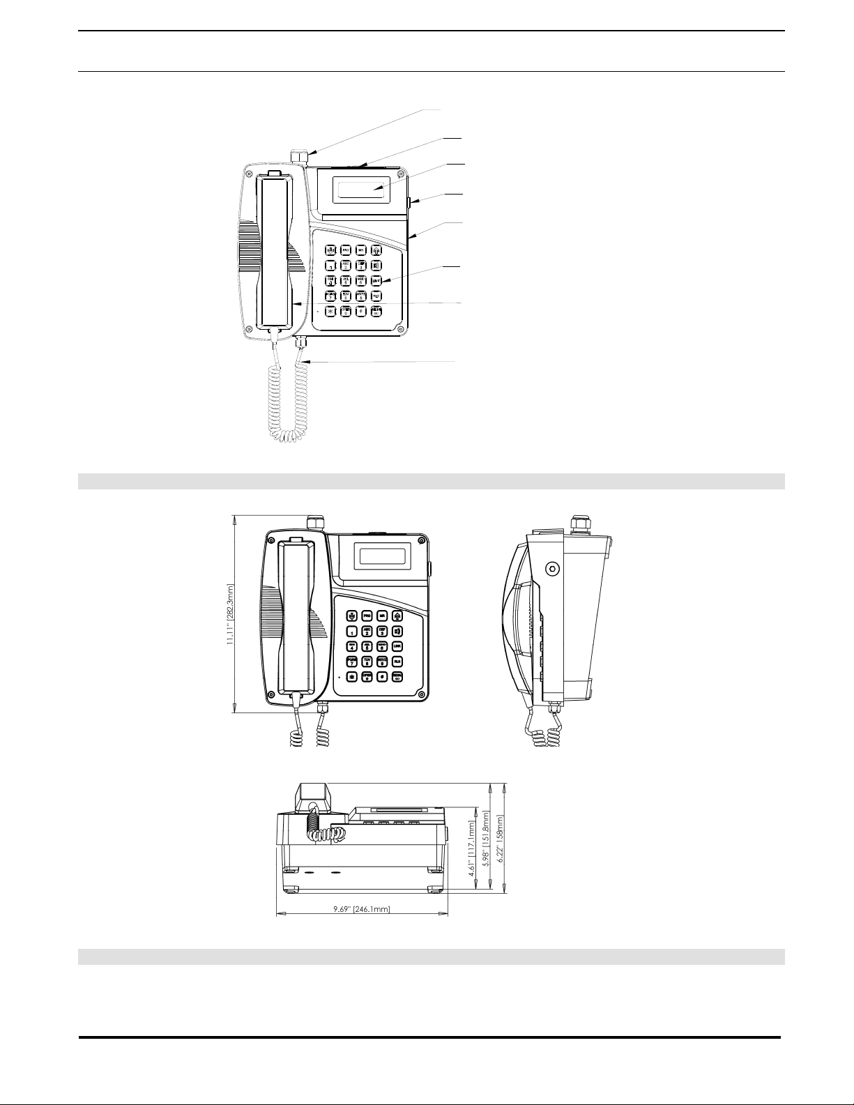
Figure 1 - Features................................................................................4
Figure 2 - Overall Dimensions...............................................................4
Figure 3 - Wall Installation of Base........................................................5
Figure 4 - Wiring....................................................................................5
Figure 5 - Temporary Mounting for Wiring.............................................7
Package Contents
(1) DTT-50 or DTT-60 Telephone
(1) Installation & Operation Manual
(1) Parts bag containing handset clips & screws, 3mm Allen key for faceplate screws &
one Ring Detect Relay Enable jumper wire.
Models
P3027 DTT-50 Telephone With Curly Cord
P3028 DTT-60 Telephone With Armored Cord
Accessories
P3031 Headset Kit
P3024 Supplemental Receiver Kit

Guardian Telecom Inc. Installation and Operation
DTT-50 & DTT-60 Telephones
Page 3
Overview
DTT Telephones
DTT telephones provide safe, reliable communications in areas that are prone to high humidity,
chemical vapors, dust and physical abuse. Hands Free operation is standard on all models and the
telephones can be programmed for speed dialing. All models have the option of installing a
Supplemental receiver that can be held against the ear opposite to the handset, in order to improve
speech recognition in noisy environments. In place of a Supplemental receiver a headset providing
even greater flexibility can be installed.
Features
Housing and Handset
•high impact thermoset – static dissipative
Mounting
•desk top or wall mounted
Audio Modes
•handset and hands-free or optional headset
Resettable Fuse
•prevents damage to the electronic circuits in the event of a high
voltage spike on the telephone line
Magnetic Reed Hook Switch
•no moving parts
LCD Display
•for ease of user interface, multi-language capable
Built In Ring Detect Relay
•250VAC 5 Ampere Ring Detect Relay, no need for external RDR
Tone (DTMF)/Pulse Operation
•factory set to tone (DTMF) dialing
•60:40 or 66:33 pulse dialing can be ordered or configured in the field
Handset Cord
•6’ heavy duty curly cord on DTT-50
•armored cord on DTT-60
Hearing-Aid Compatible (HAC) Receiver
•compatible with inductively coupled hearing-aid devices
Receiver Volume Control
•Switch on keypad provides 15dB of audio range
Wide Temperature Range
•-30º C to +60º C (-22º F to +140º F)

Guardian Telecom Inc. Installation and Operation
DTT-50 & DTT-60 Telephones
M20 ENTRY GLAND (DESK MOUNT)*
Page 4
Figure 1 - Features
Figure 2 - Overall Dimensions
4x5 KEYPAD
LCD DISPLAY
M20 ALERTER WIRING PLUG*
MAGNETIC REED
HOOK SWITCH
GLASS REINFORCED
POLYESTER FACEPLATE
M12 HEADSET SUPPLEMENTAL
RECEIVER WIRING
COIL CORD FOR DTT-50
ARMORED CORD FOR DTT-60
* BASE IS ROTATED 180° FOR WALL MOUNT

Guardian Telecom Inc. Installation and Operation
DTT-50 & DTT-60 Telephones
Page 5
Figure 3 - Wall Installation of Base
Figure 4 - Wiring
9.2" [234mm]
8.7" [222mm]
9.4" [238mm]
7.2" [184mm]
OPTIONAL GROUNDING
VOICE PATH
SWITCHING
ADJUST
RING DETECT RELAY
CONTACTS NO POLARITY
RING DETECT RELAY
ENABLE NO POLARITY
(INSTALL SUPPLIED
JUMPER WIRE)

Guardian Telecom Inc. Installation and Operation
DTT-50 & DTT-60 Telephones
Page 6
Installation
•DTT telephones are shipped from the factory set for DTMF (Tone) dialing
mode. If loop disconnect (Pulse) dialing is required program Register Number
52 appropriately.
See: Operating Modes
and Software Features.
•Follow all appropriate electrical codes and use only approved electrical fittings
for the installation.
•If required install primary surge protection external to the telephone.
•Ensure that the telephone circuits are not live by disconnecting the Tip and
Ring conductors at the demarcation block.
•If the built in Ring Detect Relay is to be utilized to activate an external alarm
ensure that the power conductors are not live.
•Using the 3mm Allen Key provided remove the four faceplate screws to
detach the faceplate from the base.
•The telephone may be installed on a flat surface or wall mounted.
Desk Top Configuration
•If the telephone is to be desk top mounted set the base in the desired
location.
Wall Mount Configuration
•If the telephone is to be wall mounted choose a location that is free of
obstructions and permits space for wiring. Mount the base with the deepest
dimension on the bottom. Mount as follows:
See: Figure 2 - Overall
Dimensions.
oThe telephone weighs 3.95 kilograms (8.68 pounds), ensure that the
mounting can support four times the weight of the unit; that is 15.8
kilograms (34.8 pounds). Wall anchors are not included; follow the
manufacture’s instructions when installing anchors.
oMounting to concrete or cinder block. Lead expansion anchors with
M4 (#8) screws are recommended.
oMounting to drywall. Hollow wall anchors (Molly Bolts) with M4 (#8)
screws are recommended.
oMounting to other surfaces. It is the responsibility of the installer to
ensure that the base is attached in such a way as to support the
weight specified above.
•Install the handset retainer clips on the faceplate using the hardware supplied.

Guardian Telecom Inc. Installation and Operation
DTT-50 & DTT-60 Telephones
Wiring
•WARNING: Use properly sized cable to ensure a gas/dust tight seal at
the cable gland to maintain an IP66 rating, (M12 – 2 to 5mm),
(M20 – 8 to 13mm). Take care not to lose parts of the gland if the cap is
removed.
•If the telephone is wall mounted hang the faceplate on the right side of the
base using two of the faceplate screws. Be careful not to lose the "O" ring
retainers.
•Insert the Tip and Ring cable through the M20 gland and connect the conductors
to the Phone-Line-In terminal block.
•If an extension telephone is installed the phone line out terminals may be
utilized. A four conductor cable can be used, or an additional cable can be run
through the spare 20mm opening; if it is not occupied for other purposes.
Tip: If cable diameter is
not in the range of the
M12 or M20 glands
provided an approved
reducer and smaller
gland can be fitted.
See: Figure 5 -
Temporary Mounting for
Wiring
See: Figure 4 - Wiring
•Install the supplemental receiver or headset if provided.
•If an external alerter device is utilized remove the M20 plug, install an appropriate
cable gland and connect the wiring to the Ring Detect Relay terminal block.
Enable the Ring Detect Relay by inserting the jumper wire provided across the
Ring Detect Relay Enable terminals.
See: Retrofitting
Headset/Supplemental
Receiver, Strobe
Light/Ringer
•Tighten the cable glands securely.
•Mount the face plate and fasten the captive screws to the base.
•Connect the Tip and Ring conductors at the demarcation block.
Tip: Torque screws to
1.65 ft/lbs (1.36Nm)
•If the built in Ring Detect Relay is utilized apply power to the conductors.
Programming the DTT
•If necessary program the features.
Testing See: Operating Modes
and Software Features
•Test the unit by calling to and from another unit on the exchange.
Figure 5 - Temporary Mounting for Wiring
Page 7

Guardian Telecom Inc. Installation and Operation
DTT-50 & DTT-60 Telephones
Page 8
Retrofitting Headset/Supplemental Receiver, Strobe Light/Ringer
•Disconnect telephone wiring at the demarcation block and ring detect relay
power at the breaker to avoid shock hazard.
•Loosen the four captive screws in the faceplate and detach the face plate from
the base.
•If the telephone is wall mounted temporarily hang the faceplate to the right side
of the base using two of the faceplate screws. Be careful not to lose the "O" ring
retainers.
See: Figure 5 -
Temporary Mounting
for Wiring
•Install the options following the instructions below.
•Tighten cable glands securely.
•Carefully replace the front plate and install all four screws.
•Reconnect telephone and ring detect relay wiring.
•Test the unit by calling to and from another unit on the exchange.
Tip: Torque screws to
1.65 ft/lbs (1.36Nm).
Headset / Supplemental Receiver
•If wall mounted install the Headset/Supplemental Receiver hanger to the wall
4" to 6" to the right of the telephone.
•Remove the M12 plug on the side of the face plate and install the accessory
cord gland.
•Insert the cord through the gland until the sleeve protrudes 1 cm into the face
plate and tighten the gland securely.
Note: Headset Kit
part no. P3031 or
Supplemental
Receiver part no.
P3024 required.
See: Figure 1 -
Features
•Connect the headset wiring to the headset earpiece and microphone terminal
block or if the Supplemental Receiver is utilized connect the wiring to the
headset earpiece terminal block connector.
•If the headset is utilized program the phone to recognize the headset (Register
Number 54).
See: Figure 4 - Wiring
See: Operating
Modes and Software
Features
Strobe Light /Loud Ringer
•Remove the M20 alerter device wiring plug from the base and install a cable
gland.
•Insert the cord through the gland into the face plate or base and tighten the
gland.
See: Figure 1 -
Features
•Connect the Strobe Light or Loud Ringer wiring to the Ring Detect Relay
terminal block.
•Enable the Ring Detect Relay by inserting the provided jumper wire across the
Ring Detect Relay Enable terminals.

Guardian Telecom Inc. Installation and Operation
DTT-50 & DTT-60 Telephones
Page 9
Field Repairs & Adjustments
Field repairs may only be carried out by qualified technicians using OEM parts.
Substitution of parts voids warranty and may pose a hazard to users of the
equipment.
See: Replacement Parts
•Disconnect telephone wiring at the demarcation block and ring detect relay
power at the breaker to avoid shock hazard.
•Loosen the four captive screws in the faceplate and detach the faceplate
from the base.
•If the telephone is wall mounted temporarily hang the faceplate to the right
side of the base using two of the faceplate screws. Be careful not to lose the
"O" ring retainers.
•Perform the necessary repairs or adjustments.
See: Figure 5 -
Temporary Mounting for
Wiring
•Carefully replace the front plate and install all four screws.
•Reconnect telephone and ring detect relay wiring.
Tip: Torque screws to
1.65 ft/lbs (1.36Nm).
Hands-free Speaker Phone Voice Switching Adjustment
•Locate the Voice Path Switching potentiometer. See: Figure 4 - Wiring
•Adjust the potentiometer clockwise to increase the receive sensitivity.
•Adjust the potentiometer counter-clockwise to increase the transmit
sensitivity.
Handset Replacement
•Disconnect the handset wiring from the terminal block. See: Figure 4 - Wiring
•If the phone is equipped with an armored cord handset, remove the
anchor screw from the armored cord lanyard.
•Loosen the handset cable gland and pull out the cord.
•Install the new replacement and tighten the gland.
•Rewire the replacement cord to the terminal block.
Supplemental Receiver and Headset Replacement
•Disconnect the supplemental receiver/headset wiring from the terminal
block.
See: Figure 4 - Wiring
•Loosen the cable gland and pull out the cord.
•Install the new replacement and tighten the gland.
•Rewire the replacement cord to the terminal block.
Hands-free Speaker Replacement
•Unplug the speaker connector from the main board.
•Remove the screws that hold the speaker cap to get access to the
speaker.
•Install the new speaker and gasket.
•Reconnect the speaker connector to the main board.
Main Circuit Board Replacement
•Label any wiring attached to the circuit board. Disconnect wiring and
ribbon cable.
•Remove the six screws holding the circuit board in place. Carefully
remove the board.
•Install the new board and replace the six screws and wiring.
Tip: Torque screws to
2.5 in/lbs (0.28 Nm).

Guardian Telecom Inc. Installation and Operation
DTT-50 & DTT-60 Telephones
Keypad Circuit Board Replacement
•Remove the main circuit board as described above.
•Remove and replace the keypad circuit board.
•Replace the main circuit board and wiring as described above.
LCD Display and Keypad Membrane Replacement
•The LCD and the keypad membrane are not replaceable in the field. The
telephone must be returned to Guardian Telecom or an authorized
service depot for repair.
Fuses
•There are no replaceable fuses in the DTT.
•The phone line fuse on the circuit board of all models is of the resettable
type and is not replaceable. If the fuse trips due to an external event it will
reset in a short period of time. The duration will depend on ambient
temperature and other factors. If the fuse trips repeatedly check the
telephone system wiring.
•The Ring Detect Relay fuse is a 5 Ampere, fast blow fuse potted on the
circuit board. If the fuse blows the circuit board must be replaced.
Tip: The fuse protects
the Tip and Ring line
from the telephone
system. It is usually
powered at 48 volts DC
and must not be
connected to 120VAC or
230VAC.
Key Functions
While Programming
..............Hands free mode
..............Puts phone in programming mode
or ...Scrolls through registers
..............Returns to main register prompt
..............Stores number in selected register
..............Returns to main register without changing contents of selected register
..............Clears selected register and switches back to main register prompt
While Operating
............. Hands free mode or returns to on-hook
or ...Scrolls through registers in Phone Book mode
or ...Volume control during conversation
..............Timed disconnect (same as Flash) for some CO or PABX functions
..............Disconnects from phone line
.............Dials number in buffer
..............Displays register 0 to 9 for quick dialing
(twice) ..Displays register 00 to 19 for phone book dialing, can scroll with arrow keys
Page 10

Guardian Telecom Inc. Installation and Operation
DTT-50 & DTT-60 Telephones
Page 11
Operating Modes and Software Features
Programming Mode:
1. To enter Programming Mode take the phone off hook by removing the handset from the cradle or by
pressing the [SPK] key. During the programming process do not switch Audio modes.
2. Press the [PRG] key for 1 second until a beep tone is heard and the programming prompt is shown on the
display. The pass code prompt will be shown on the second line of the LCD.
3. Enter the pass code. It must be four characters long, the numeric keys, the ‘*’ and the ‘#’ are valid keys.
The user entered code will not be displayed on the LCD.
Note: The telephone has provision for two pass codes, either one of which will allow access to
Programming Mode. Factory settings are 1234 and 5678.
4. Pass code check:
A. If the entered code is incorrect an invalid message will be shown on the second line for two
seconds and the phone will go back to on hook
B. If the entered code matches the preset code, the phone will be in programming mode and the
main register prompt will be shown:
Enter REG #: ..
[REG 0-19, 50-69]
5. Register number selection:
A: Register Code entered:
Enter a two digit register number or use the arrow keys to scroll to the desired register. Once the
first number is entered the second key also has to be a number. Other keys entered following the
first key (except the arrow keys and [PRG] key) will result in an invalid message being displayed
on the LCD for two seconds and two alert beep tones. The LCD will switch back to the main
register prompt.
Once the register number is entered it will be shown on the first line. The previous setting of the
register will also be displayed:
REGxx=xxxx
B. Scrolling:
The first key can be an arrow key (the [↑], and the [↓] keys). If an arrow key is activated the
selected register will be shifted to the adjacent register (the next higher or lower depending on
whether the entered key is the [↑] or the [↓] key). The register number will be shown on the first
line and the contents of the register will be displayed. The phone is then ready to accept the
register setting.
Register scrolling can run from registers 00 to 19 (phone number registers), and from 50 to 69
(feature registers). The arrow keys will shift the register within the range 00 to register 19 but will
not jump to registers 50 to 69. To access registers 50 to 69 press [RLS] to get back to the main
register prompt, then enter a register within the range of 50 to 69. Then use the arrow keys to
scroll through registers 50 to 69.
C. Programming phone numbers:
If the selected register is within the range 00 to 19 it is a phone number register that can contain a
maximum of twenty digits. The “#” key is counted as one digit and will be treated as a three
second pause. This may be required if an access number i.e. “9” must be entered to get an
outside line.
Enter the new phone number to replace the previous setting.
a. Use the [MR] key to store the setting to the non-volatile memory. A beep tone will be
heard and the store message will be shown on the display for one second. The LCD
will then switch back to the main register prompt.
b. Use the [RLS] key to cancel the entry leaving the previous phone number unchanged.
The display will switch back to the main register prompt.
c. Use the [LINK] key to clear the contents of the register and switch back to the main
register prompt.

Guardian Telecom Inc. Installation and Operation
DTT-50 & DTT-60 Telephones
Page 12
D. Programming Access Codes:
If the selected register is 50 or 69, it is a four digit Programming Access Code register.
If desired enter a new pass code to replace the previous code. The pass code has to be four
characters long. The numeric keys, the ‘*’ and the ‘#’ are valid keys for pass code.
a. Use the [MR] key to accept the new code. A second prompt will be shown with the
newly entered pass code. Check and compare the pass code on the LCD display to
the pass code on the programming sheet. Press the [MR] key again to store the new
code to the non-volatile memory. A beep tone will be heard and the store message will
be shown on LCD for one second. The LCD will switch back to the main register
prompt.
b. Press the [RLS] key to cancel the newly entered pass code leaving the existing pass
code unchanged. A “Code not saved!” message will be shown for one second and the
display will switch back to the main register prompt.
Note:
For convenience the DTT telephone has two Access Code registers either one of which
will allow entry to programming mode. If the Access Codes are to be replaced, they
should be changed one at a time. Confirm the new code by using it to get into the
programming mode. If the new code does not work, use the other Access Code to restore
the code that was previously changed.
Always use the Programming Sheet to record the Access Codes.
If both Access Codes are forgotten the phone has to be sent back to Guardian Telecom
Inc. or an authorized service center for the Access Codes to be restored.
E. Configuration Codes:
If the selected register is within the range 51 to 68, it is a one digit Configuration Code register.
Use the Programming Sheet as a guide to select the settings. Enter the new code to replace the
previous setting.
a. Use the [MR] key to store the setting to the non-volatile memory. A beep tone will be
heard and the store message will be shown on the display for one second. The LCD
will then switch back to the main register prompt.
b. Use the [RLS] key to cancel the entry leaving the previous Configuration Code
unchanged. The display will switch back to the main register prompt.
F. Default Settings:
When register 51 is set at ‘2’ all the configuration codes and the Pass Codes will remain
unchanged while the phone is still in the Programming Mode. Once the phone goes from on
hook to off hook again all the Configuration codes and the Pass Codes will be reset to the default
settings and register 51 will be reset to ‘1’. The phone number registers will remain unchanged.
G. Exiting Programming Mode:
Press and hold the [PROG] key to exit programming mode. The exit programming message will
be shown and the phone will go back to on hook.

Guardian Telecom Inc. Installation and Operation
DTT-50 & DTT-60 Telephones
Page 13
Programming Sheet:
Register
number Functions Descriptions Entered Codes Parameters Remarks
00 Phone number at 0
01 “ “ “ 1
02 “ “ “ 2
03 “ “ “ 3
04 “ “ “ 4
05 “ “ “ 5
06 “ “ “ 6
07 “ “ “ 7
08 “ “ “ 8
09 “ “ “ 9
10 “ “ “ 10
11 “ “ “ 11
12 “ “ “ 12
13 “ “ “ 13
14 “ “ “ 14
15 “ “ “ 15
16 “ “ “ 16
17 “ “ “ 17
18 “ “ “ 18
19
Speed dial
phone
numbers
“ “ “ 19
Maximum 20
digit phone
number
Registers 00 to 09 can be
accessed for dialing by
pressing MR once
followed by a number 0 to
9.
Registers 00 to 19 can be
accessed for dialing by
pressing MR twice and
entering a number 00 to
19. In addition the
up/down arrows can be
used to scroll through the
registers. When the
desired number is located
pressing MR will cause
the number to be dialed
out.
20 - 49 Not Used
50 First Access Code
(numeric keys, *, and #)
4 characters
Default = 1234
51 Default
Settings
1 = user, 2 = default
Factory defaults:
50 = 1234 (Access code)
51 = default settings
52 = DTMF dialing
53 = English Display
54 = Speaker Mode
55 = Flash
56 = 5, Headset Mic gain
57 = 3, Handset Mic gain
60 = 60minutes Talk Time
61 = 32 dialing digits
62 = 5 hand/headset
volume
63 = 5 speaker volume
64 = 1
65 = 2
66 = 6
67 = 5 TX gain
68 = 6 Rx gain
69 = 5678 (Access code)
1 digit code When register 51 is set at
‘2’, all the configuration
codes and the Pass
Codes will remain
unchanged while the
phone is still in the
Programming Mode.
Once the phone goes
from on hook to off hook
again, all the
configuration codes, and
the Pass Codes will be
reset to the default
settings and register 51
will be reset to ‘1’. Phone
number registers will not
be changed.
Default = 1
52 Dialing Modes
1 = DTMF (RS 470)
2 = DP 60:40 (10pps)
3 = DP 66:33 (10pps)
4 = DTMF (BTR 21)
1 digit code
Default
North America = 1
Europe = 4

Guardian Telecom Inc. Installation and Operation
DTT-50 & DTT-60 Telephones
Page 14
53 LCD Display Languages
1 = English
2 = French
3 = Spanish
1 digit code
Default = 1
54 Hands-free Devices
1 = speaker, 2 = headset
1 digit code
Default = 1
55 Timed Break
1 = 280ms, 2 = 600ms
1 digit code
Default
Europe = 1
North America = 2
56 Headset Microphone Gain (1-8) 1 digit code Default = 3
57 Handset Microphone Gain (1-8) 1 digit code Default = 3
58 -59 Not used
60 Talk time (minutes)
1 – 9 = 1 to 9 minutes
0 = 60 minutes
1 digit code
Default = 0
61 Max. digits in manual dialing
1-9 = 3+(1 to 9) digits,
0 = 32 digits
1 digit code
Default = 0
62 Handset / headset volume
after reset (1 – 8)
2 dB / step
1 digit code
Default = 5
63 Speaker volume after reset
(1 – 8)
2 dB / step
1 digit code
Default = 5
64 Voice switch speed between
transmit & receive (1 – 4)
1= max speed
4= min speed
1 digit code.
Using the
factory setting
recommended
Default = 1
65 Background noise offset level
(1 – 4)
1=120mV, 2=180mV
3=240mV, 4=300mV
1 digit code.
Using the
factory setting
recommended
Default = 2
66 Background noise & soft clips
(1 – 8)
1 = Tx soft clip
2 = Rx soft clip
3 = Tx, Rx s.c.
4 = BGN on
5 = BGN, Tx s.c
6 = BGN, Rx s.c.
7 = BGN, Tx, Rx, s.c.
8 = BGN off,
1 digit code.
Using the
factory setting
recommended
Default = 6
67 Transmit gain (1- 8) 1 digit code.
Using the
factory setting
recommended
Default = 5
68 Receive gain (1 – 8) 1 digit code.
Using the
factory setting
recommended
Default = 6
69 Second Access Code
(4 characters)
(numeric keys, *, and #)
4 digit code
Default = 5678

Guardian Telecom Inc. Installation and Operation
DTT-50 & DTT-60 Telephones
Page 15
User Operating Mode:
When the handset is off the cradle or the [SPK] key is pressed the phone will go off hook. The LCD
will display the greeting message and the current Audio mode. While the phone is off hook and it
detects a Call Disconnect pulse from the CO line or PABX, the phone will go on hook, even with the
handset off the cradle.
1. Audio Modes:
The DTT telephone has two Audio Modes Handset and Hands-free. The LCD display will show
the current status of the Audio mode. The [↑] key and [↓] key are volume control keys.
Pressing these two keys will adjust the volume of the current hearing device
a. Handset mode:
When the phone is on hook or while it is off hook in Hands-free Mode, removing the
handset from the cradle will set the phone to the Handset Mode. In this mode the
speaker and the hands-free microphone are off. The headset receiver and
microphone are off if the headset is configured to replace the speaker. The volume
control keys will adjust the volume on the handset earpiece volume. The phone will go
back to on hook if the handset is returned to the cradle.
b. Hands-free Mode:
When the phone is on hook, or while it is off hook in Handset Mode pressing the [SPK]
key will set the phone to the Hands-free Mode. After the phone has switched from
Handset Mode to Hands-free Mode returning the handset to the cradle will not put the
phone on hook. The phone will go back to on hook if the [SPK] key is pressed.
Hands-free Mode can be configured to Speaker Phone or Headset by setting the
contents of register #54 to 1 or 2 respectively. Speaker phone capability is standard
however a headset is optional.
i. Speaker Phone Mode:
When the phone is configured to Speaker Phone the hands free MIC and the
speaker are on. The handset MIC and headset are off. The volume control
keys will adjust the speaker volume.
ii. Headset Mode:
When the phone is configured to Headset Mode, the hands free MIC, speaker,
and the handset are off. The volume control keys will adjust the volume on
headset earpieces.
Note: be sure that Register #54 is set correctly.
2. Dialing Modes:
There are four signaling modes in the DTT telephone.
A. DTMF dialing modes (RS 470 and BTR 21):
In the DTMF mode, using keypad dial, redial, or Phone Book dial will result in having the
phone dialed in DTMF tones.
B. Pulse dialing (break/make ratio of 60:40) mode:
In the 60:40 Pulse dialing mode, using keypad to dial, redial, or Phone Book dial will
result in having the phone number dialed in pulse with the break/make of 60:40 at
10pulses/sec. In this mode the Link key (timed break key), the ‘*’ key, and the ‘#’ key
are not supported.
C. Pulse dialing (break/make ratio of 66:33) mode:
In the 66:33 Pulse dialing mode, using keypad to dial, redial, or Phone Book dial will
result in having the phone number dialed in pulse with the break/make of 66:33 at
10pulses/sec. In this mode the Link key (timed break key), the ‘*’ key, and the ‘#’ key
are not supported.

Guardian Telecom Inc. Installation and Operation
DTT-50 & DTT-60 Telephones
Page 16
3. Numeric keys, [*] key, and [#] key on the Keypad:
While in the Operating Mode, all the numeric keys, the ‘*’ key, and the ‘#’ when pressed will be
dialed out, (if the phone is set to pulse dialing the [*] and [#] keys are not supported). The
maximum number of characters that can be dialed out are 32. The dialed out characters will be
displayed on the LCD starting from the first character to the left on the first line and ending at
the last character to the right on the second line. The dialed number on the display will be
maintained for 6 seconds, then the display will switch back to show the Audio Mode status until
further numeric keys are pressed.
4. The [↑] and [↓] keys:
The up and down arrow keys adjust the volume of the hearing device currently being used.
Each press of these keys will increase or decrease the volume by 2 dB within a range of 15 dB.
The LCD will display the current volume setting for two seconds then switch back to show the
Audio Mode status.
5. [Link] key:
The [Link] key which is sometimes referred to as [Flash] will provide a timed disconnect to the
current on the phone line. The period can be configured to 280ms or 600ms and is required for
some Central Office or PABX functions.
6. [RLS] key:
The [RLS] key will disconnect the phone from the phone line for one second to reset the phone
line for next call.
7. [Redial] key:
Pressing the [Redial] key after going off hook will dial out the last keys stored in the dial buffer.
It may be different than all the keys that were pressed in the previous call.
The number dialed out will be displayed on the LCD starting from the first character to the left on
the first line and ending at the last character to the right on the second line.
The dialed number will be displayed for two seconds then the LCD will switch back to show the
Audio Mode status.
The arrow keys will resume the volume control function.
Subsequent keypad dialing is resumed.
8. Quick dialing and Phone Book Call:
Quick dialing and Phone Book calling must be used just after going off hook. If manual dialing
is used, Quick dialing and Phone Book will be disabled.
A. Quick dialing:
There is provision for 10 Quick dialing phone numbers in the phone. To activate Quick
dialing, press the [MR] key.
The register number prompt will be displayed:
Enter REG #: ..
[REG 0 to 9]
Press one numeric key (0 to 9). The phone number in the register will be dialed out to
the phone line as well as being displayed on the LCD. The dialed number will be
displayed for two seconds then the LCD will switch back to show the Audio Mode status.
The arrow keys will resume the volume control function. Subsequent keypad dialing is
resumed.
B. Phone Book dialing:
There are twenty phone numbers in the Phone Book including the 10 Quick dialing
phone numbers. To activate the Phone Book press [MR] twice.
The register number prompt will be displayed:
Enter REG #: ..
[Phone List]

Guardian Telecom Inc. Installation and Operation
DTT-50 & DTT-60 Telephones
Page 17
Enter a two digit number or use the arrow keys to scroll through the register. The
associated phone number will be displayed.
Use the [↑] or [↓] keys to shift through the Phone Book.
Press [MR] key to dial out the current register phone number.
The dialed number will be displayed for two seconds then the LCD will switch back to
show the Audio Mode status. The arrow keys will resume the volume control function.
Subsequent keypad dialing is resumed.
Note:
When a phone number register is clear, calling it through Quick dial or
Phone Book dialing will result in no dialing at all.
All phone number registers that are not used should be cleared.
9. Time out:
The time out counter will enforce a fixed call duration which is programmable from between 1
minute to 9 minutes, or alternatively 60 minutes, starting from the moment the phone is off hook.
It will generate 3 beep tones, and display a time out message on the LCD ten seconds prior to
disconnecting the call. This feature is applicable in both Handset and Hands-free modes. This
feature is useful when the user forgets to return the handset back to the cradle, or does not
press the [SPK] key to hang up the call while the phone is in the Hands-free Mode.
(This feature can set to maximum 60 minutes).
After time out the phone is disconnected from the phone line. The phone will ring when there is
an incoming call. The handset has to be returned to the cradle for the phone to be used in
handset or hands-free mode to answer the call.

Guardian Telecom Inc. Installation and Operation
DTT-50 & DTT-60 Telephones
Page 18
Product Specifications
Performance
AUDIBLE RANGE FREQUENCY RESPONSE 300 –3400 HZ
HANDS FREE SPEAKER OUTPUT (MAX @1KHZ) ~85dB @1METER
RECEIVER VOLUME ADJUSTMENT 8STEPS,2 dB/STEP
SPEED DIAL 10 REGISTERS OF 20 DIGITS EACH
PHONE BOOK DIAL 20 REGISTERS OF 20 DIGITS EACH,(INCLUDES SPEED DIAL
NUMBERS)
FLASH 280/600 mSEC TIMED DISCONNECT
REDIAL 32 DIGITS MAXIMUM
NORTH AMERICAN CONFIGURATION
DIALING METHOD DTMF OR 40:60 PULSE AT 10 PPS
EUROPEAN CONFIGURATION
DIALING METHOD DTMF OR 33:66 PULSE AT 10 PPS
CONFORMS TO
RESIDENTIAL AND INDUSTRIAL AREAS
ETSI TBR 38: MAY 1998 (ACOUSTICS)
ETSI TBR 21: JANUARY 1998 (TELEPHONE NETWORK)
Electrical
RINGER SENSITIVITY 40 –100 V, 16 –25 HZ
LINE VOLTAGE 24 –56 VDC
LOOP CURRENT 22 -100 mA
CONNECTION METHOD TERMINAL BLOCKS
FUSE -MAIN TELEPHONE CCT 250 mA –AUTO RESET
FUSE –RING DETECT RELAY 5AMP 250 VOLT FAST BLOW
RINGER OUTPUT >85 dB @1M
RINGER IMPEDANCE WITHOUT RING DETECT RELAY >7K OHMS @25 HZ,30-90 VAC
>4K OHMS @50HZ,30-90 VAC
RINGER IMPEDANCE WITH RING DETECT RELAY >4K OHMS @25 HZ,30-90 VAC
(RDR NOT RECOMMENDED @50HZ)
SET IMPEDANCE 600 OHMS NOMINAL
MAXIMUM LOOP 15,000 FT (4,600 M)OF 22 AWG COPPER
Environmental
INGRESS PROTECTION RATING IP66
OPERATING TEMPERATURE -30O TO +60O C(-22O TO +140O F)
STORAGE TEMPERATURE -50O TO +80O C(-58O TO +176O F)
HUMIDITY 0TO 95% RH
DUSTPROOF FULLY GASKETED ENCLOSURE
Mechanical
HOOK SWITCH (CRADLE SWITCH)LIFE >1 000 000 OPERATIONS
HOUSING MATERIAL GLASS FILLED POLYESTER (CARBON LOADED)
HANDSET MATERIAL GLASS FILLED POLYESTER (CARBON LOADED)
DIMENSIONS (H X WX D) WALL MOUNTED 282 X 246 X 158 MM (11.1 X 9.7 X 6.2 INCHES)
NET WEIGHT 3.95 KG (8.68 LBS)
MOUNTING WALL STRENGTH REQUIREMENT 15.8 KG (34.8)LBS
MICROPHONE NOISE CANCELING
RECEIVER HEARING AID COMPATIBLE (HAC)
MOUNTING DESK OR WALL
WIRING ACCESS 2X M20 &1X M12 CABLE GLAND ENTRY POINTS

Guardian Telecom Inc. Installation and Operation
DTT-50 & DTT-60 Telephones
Compliance
ENVIRONMENTAL IP-66
ROHS COMPLIANT
Replacement Parts
Part No. Description
P3025 DTT Replacement Handset c/w curly cord.
P3026 DTT Replacement Handset c/w armored cord.
P002254 Magnetic reed hook switch
P004123 Nylon fastener for hook switch
P006582 Membrane Gasket for Handset Microphone.
P006583 Membrane Gasket for Handset Receiver.
P006690 M20 Gland, ATEX compliant
P006668 M20 Plug, ATEX compliant
P006679 M12 Gland, ATEX compliant
P006862 M12 Plug, ATEX compliant
P006692 M4 Faceplate screws (4 required)
P006696 0-Ring gaskets for faceplate screws (4 required)
P006675 Faceplate gasket (do not order if purchasing P007335 as it is included)
P007191 Molded cover for encapsulated circuit board.
P007198 Main Circuit board for desk top telephone, encapsulated.
P007199 Keypad circuit board with HF microphone
P007335 Replacement Faceplate c/w Keypad membrane, LCD, gaskets.
P007177 Telephone housing base
P006819 Speaker
P006614 Handset retainer (qty 2 required)
P006617 Allen key for faceplate screws
Page 19

Guardian Telecom Inc. Installation and Operation
DTT-50 & DTT-60 Telephones
Page 20
Warranty
Guardian Telecom warrants your product to be free of defects in material and workmanship for a period
of one year. Guardian Telecom will repair or replace any defective unit that is under warranty free of
charge.
This warranty is null and void if any non-authorized modifications have been made to this product, or if
it has been subjected to misuse, neglect, or accident. This warranty covers bench repairs only; such
repairs must be made at Guardian Telecom or an authorized service depot. Guardian Telecom is not
responsible for costs incurred for on-site service calls, freight, or brokerage.
A return authorization must be obtained prior to warranty claims or repairs.
Disclaimer
The products covered by this manual are designed for use in Industrial Environments and/or Hazardous
Locations. Due to the range of possible applications for these instruments the manufacturer will not be
responsible for damages or losses of any kind suffered as a result of the use of this product, including
consequential damages.
Warning
This device may be opened and reassembled by qualified personnel only, for the purposes of installing
the product, making adjustments and replacing components, following the instructions in the product
manual. Before opening this telephone disconnect the wiring at the demarcation block.
High voltages may be present in this product when connected to telephone wiring.
Service Telephone Number
1-800-363-8010
Guardian Telecom provides a customer service telephone number which is toll-free within North
America. If you need assistance when installing or operating this product, please call the toll-free
telephone number between regular business hours (8:00AM-5:00PM), Mountain Standard Time. If you
are calling outside of regular business hours, please leave a detailed message, and a member of
Guardian Telecom’s Service Department will return your call as soon as possible. If your product
requires service, Guardian personnel will supply you with an RMA (return materials authorization)
number over the telephone or through our web site product return page. This number must be included
with your return address and the name of the person to contact.
Guardian Telecom Inc.
7552 - 10th Street N.E.
Calgary, Alberta, Canada T2E 8W1
Toll-free 1-800-363-8010
Ph. (403) 258-3100
Fax. (403) 253-4967
www.guardiantelecom.com
Feedback
Guardian Telecom continually strives to make reliable, durable, and easy to use products. If you, as an
installer or user of our equipment, have any suggestions for improvements to this or any of our products
or documents, including this manual, we would appreciate hearing from you.
This manual suits for next models
1
Table of contents
Other Guardian Telephone manuals