Guest 502A User manual

MODEL 502A
MODEL 502AMODEL 502A
MODEL 502A
BEAMER
Remote Control Spotlight
Owners Manual
INSTALLATION AND OPERATION
INSTRUCTIONS
IMPORTANT!
READ THESE INSTRUCTIONS BEFORE
INSTALLING OR USING THIS PRODUCT
KEEP THESE INSTRUCTIONS FOR FUTURE REFERENCE.

2
Description
DescriptionDescription
Description
The GUEST 502A BEAMER remote contro spot ight uses a sophisticated, high-powered ha ogen
bu b. The penetrating 100-watt beam can i uminate objects up to one (1) mi e away.
A Guest Beamer spot ights can rotate 355° and move up and down through an 80° arc. A though
the mode 502A cannot be upgraded for wire ess contro , mu tip e contro pane s can be insta ed
using the 729828-P dua station contro . The mode 502A comes comp ete with spot ight, remote
contro pane , and 15 feet (4.6m) contro cab e.
This unit is designed for 12 vo t DC operation on y.
# Tools and additional materials required
Electric drill with 1/2"(13mm), 5/16"(8mm) and 3/16"(5mm) bits
Wire crimping tool
hillips-head screwdriver
2 7/16", (11mm) wrenches
Non-silicon sealant (StarBrite
Boat Caulk #83801 or equivalent.)
4 1/4" (6mm) Stainless Steel pan or socket head machine bolts
(Bolt length = mounting surface thickness plus 1" (25mm)
4 1/4" (6mm) Stainless Steel large O.D. flat fender washers, lock washers and hex nuts.
1 10 amp fuse and fuse holder (or circuit breaker)
1 2 amp fuse and fuse holder (or circuit breaker)
Marine grade plywood
You will also need marine grade stranded, 2-conductor, 12-gauge wire to connect the
spotlight and the control panel to 12-volt DC power sources. (Use 10-gauge wire if the
light will be more than 30 feet (9mm) from its power source.)

3
Installation
InstallationInstallation
Installation
Mounting the Spotlight
1. Se ect a horizonta , smooth surface to mount the spot ight on. Be sure you wi have access
to the underside of the chosen ocation, and that you wi be ab e to dri ho es there without
damaging existing wiring or structures. Avoid ocations where ines, anchors, sai s or other
hazards might damage the ight.
NOTE: Mounting the ight as far forward or as high as possib e can he p to reduce ref ected
g are from the deck when the ight is in use.
2. Remove the foam spot ight base gasket from the box and use it as a temp ate. Note gasket
orientation: Front mounting ho es are further apart than the rear ho es. Mark the ocation of
the four corner ho es and the center ho e square y onto the mounting surface with penci .
3. Dri four 5/16" (8mm) ho es and one 1/2"(13mm) ho e in the center through the mounting
surface at the marked points.
NOTE: Always wear eye protection when using power tools.
4. Insta the foam gasket on to the base of the spot ight, making sure that the seven wires exit
through the center ho e in the gasket.
5. Feed a seven wires coming out of the base of the ight, through the center ho e in the
mounting surface. A small amount of a non-si icone sea ant, (such as StarBrite Boat Cau k
#83801), can be app ied to where the bo ts and the wires penetrate the mounting surface.
6. It is recommended that you use marine qua ity p ywood as a back-p ate.
CAUTION!
Si icone based sea ants may cause damage to the foam gasket or to the base of the ight.
7. P ace the ight on the mounting surface, ens facing forward, and a ign the four ho es in the
ight base and the foam gasket with the four corner ho es dri ed into the mounting surface.
8. Fasten the spot ight secure y to the mounting surface using four 1/4" (6mm) bo ts, f at
washers, ock washers and nuts (not inc uded). Do not over tighten. Large f at fender
washers are recommended.
9. Insta the gray contro cab e between the ight and the p anned ocation of the contro pane .
Avoid running the cab e across sharp edges or where it may be exposed to extreme heat.

4
Mounting the Control anel
1. Se ect a convenient mounting ocation for the contro pane . Be sure you wi have access to
the area behind the ocation, and that you wi be ab e to dri ho es there without damaging
existing wiring or structures. Do not p ace the contro where it cou d interfere with the safe
operation of the vesse or vehic e. Avoid mounting the contro pane on a curved surface, or
f at on its back in a ocation that wou d be exposed to direct rain or spray.
2. Use the sma foam gasket inc uded in the box as a temp ate to mark the ocation of the
ho es to be dri ed. Dri two 3/16” (5mm) ho es for the mounting screws and one ½” (13mm)
ho e in center through the mounting surface as shown in sketch be ow (not to sca e), make
sure that the ho es are horizonta to each other.
1.5"[38mm]
3.0"[76.5mm]
2 Places
3/16"[5mm] hole
hole
1/2"[13mm]
reference
3.26"[82.8mm]
reference
3.9"[100.2mm]
3. Feed a of the Contro Pane wires through the center ho e of the sma gasket, then p ace
the gasket underneath the contro through the two threaded mounts.
Feed a the contro wires through the ½” (13mm) dri ed ho e of mounting surface, a small
amount of a non-si icone sea ant, (such as StarBrite Boat Cau k #83801) can be app ied
where the wires penetrate the mounting surface.
Fasten the contro onto mounting surface using the provided two f at fender washers and
ock nuts. Tighten the nuts enough to s ight y compress the sma gasket.
Electrical connections
The Guest Mode 502A spot ight has two types of wiring connections.
They are:
Control Cable wires - the sma wires within the gray casing that carry your commands from the
contro pane to the spot ight.

5
•Power supply wires- are B ack (-) and Red (+) wires without connectors that bring 12-vo t DC
power into the spot ight and into the contro pane .
CAUTION!
DO NOT CONNECT THE CONTROL WIRES (with connectors)
TO ANY OWER SU LY WIRES.
DO NOT REVERSE THE RED ( OSITIVE) AND BLACK (NEGATIVE) OWER WIRES.
This spot ight requires a power source of 12-vo t DC power that is capab e of supp ying 10 amps of
current even when other equipment is operating. For best resu ts, run two new power supp y wires
from the red (+) and b ack (-) power wires of the ight direct y to the main 12-vo t DC accessory
pane . Insta fuses and fuse ho ders as shown in diagram. A 10-amp circuit breaker can be insta ed
instead of an in- ine 10-amp fuse. If the ight wi be mounted ess than 30 feet, (9m) from its power
source, use 12-gauge (3mm) power supp y wires. If the distance wi be more than 30 feet, (9m) use
10 gauge (5mm) wires.
Comp ete the wiring connections as shown be ow:
Foam Gasket
10-12 ga. Butt Connector
10 Amp Fuse
(or circuit breaker)
Black
12 volts DC
Red
12 volts DC
1.
Connect the wires from the spotlight
to SAME colors on provided cable
Cable Male Plugs
on this end
2.
Connect the control wires to
SAME colors on provided cable
10-12 ga. Butt Connector
Black
12 volts DC
Red
12 volts DC 2 Amp
Fuse
Do not use
blue wires
RED
BROWN
GREEN
BLACK
WHITE
RED

6
Operation
OperationOperation
Operation
To move the spot ight, press one of the directiona buttons firm y. By pressing a horizonta button
and a vertica button together, the ight wi move both vertica y and horizonta y at the same time.
Right
Left
Up
Down
Green LED
Any Control switch Activated
Red LED
SPOT LIGHT ON
LIGHT ON/OFF
SWITCH
recautions
DO NOT ook direct y into the spot ight whi e operating.
DO NOT cover the ight with a fabric cover or any other f ammab e materia . Accidenta activation
may resu t in a fire hazard.
DO turn the spot ight toward the contro station when not in use. If the spot ight is accidenta y
activated during day ight, the operator wi be more ike y to notice and turn the spot ight off before
draining a battery.
Maintenance
Under norma conditions, mi d detergent and water wi be sufficient to keep the spot ight c ean.
Avoid using caustic chemica s or abrasives as they may damage the housing. No ubrication is
necessary.
For replacement parts you can call The Guest Co. at 203-235-4421 or contact your local
dealer.
Item Part #
Rep acement 100 Watt bu b kit 729493
Contro pane 729827-P
Dua Station Kit 729828-P
Lower drive motor ( eft/right) U-3135
Extension Cab e Kit 729528
Base mounting gasket For Spot ight 728372
Safety g ass ens B-23186
Re ay PC Board 502A 729976
Spot ight Ref ector D-23127
Gasket For Contro Pane 729962

7
CONTRO PANE S AND PC BOARDS USED WITH GUEST MODE S 500A, 501A, or 503A WI NOT OPERATE
THE MODE 502A SPOT IGHT.
roubleshooting
roubleshootingroubleshooting
roubleshooting
Under norma use, your Guest Beamer spot ight wi provide you with many years of re iab e
service.
If an operational problem occurs:
. Confirm that all fuses are intact. If a fuse has b own, do not rep ace the fuse unti the cause of
the prob em has been ocated and corrected. NEVER rep ace a b own fuse with a higher va ue
fuse.
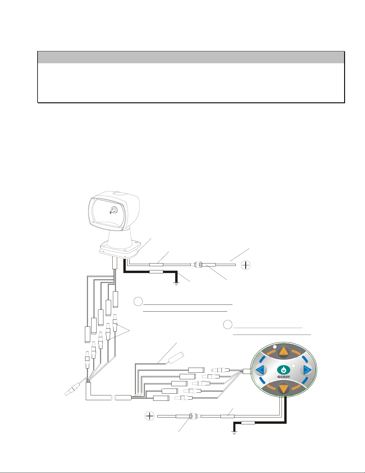
Most problems are caused by poor wiring connections. Confirm that a wiring connections
are accurate and we made. Be sure that the spot ight and contro are connected to a 12-vo t
DC power source capab e of supp ying 10-amps even whi e other equipment is operating. (see
diagram on page five).
If the spotlight does not move or light:
Remove the 4 bo ts that fasten the spot ight onto the mounting surface and gent y ift the unit unti
you can see inside its base. Avoid cutting any wires. Gent y inspect the wiring inside the base
for broken connections. Examine the circuit board for oose p ug connectors, b ackened
components or corrosion. Rep ace the circuit board if it appears damaged. If there are no oose
wires or signs of water penetration, re-insta the spot ight and then rep ace the contro pad. If
there are signs of water damage, return the spot ight and contro to the Guest Service
Department for repair. Inc ude information about how and where the spot ight was insta ed.
If the spotlight moves properly but does not light: Examine the ha ogen bu b. Rep ace it if it
appears disco ored or broken. If the bu b appears norma , test for a fau ty re ay by istening at
the base of the ight whi e someone e se activates the bu b using the contro pane . If no "c ick" is
audib e, or if a "chattering" sound is not heard, rep ace the Re ay PC board. NOTE: Low vo tage
or a fau ty circuit board may cause simi ar symptoms.
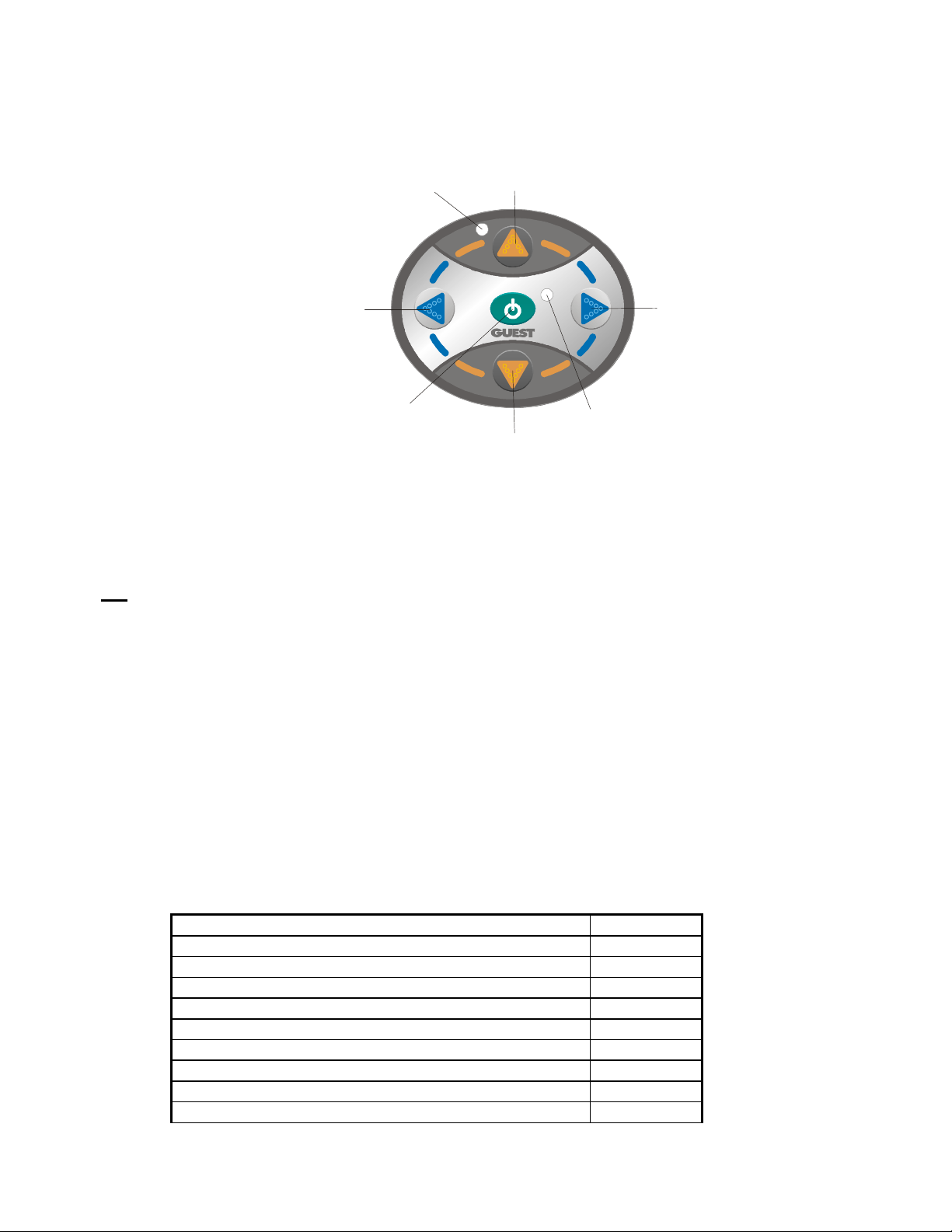
If the spotlight will not move left or right but operates norma y otherwise, isten at the base of
the ight whi e someone e se presses the eft/right directiona buttons. If the ower motor makes
no sound when activated, rep ace ower motor.
If the spotlight does not move in one direction only (i.e. up, but not down or eft, but not right)
and the wiring has been checked, rep ace the contro pane .
If your ight has a prob em that is not described above, return it to the Guest Service Department
for a free inspection. Be sure to inc ude a brief description of the prob em, and proof of purchase
(if requesting warranty service), and your phone number.

8
LIMITED WARRANTY
For one (1) year from the date of origina purchase, The Guest Co. wi , at its discretion, repair or
rep ace for the origina consumer, free of charge, any parts found defective in materia or
workmanship. A transportation charges under this warranty must be borne by the consumer.
Proof of purchase is required: A computerized register receipt is required. Hand-written receipts
are not accepted for warranty proof of purchase. In the absence of a receipt, warranty period
wi be ca cu ated from date of manufacture printed or stamped on the product.
There is no other expressed warranty. Imp ied warranties, inc uding those of merchantabi ity and
fitness for a particu ar purpose, are imited to one year from the date of purchase. This is the
exc usive remedy and consequentia damages are exc uded where permitted by aw.
Fax: (707) 226-9670 Website: www.marinco.com
730329 REV B 3429
Table of contents