Guildline 6624CT-3000 User manual

Operation Manual
For The
6624CT-3000
High Current DC Transformer
www.guildline.com
NOTICE
The contents and information contained in this manual are proprietary to
Guildline Instruments Limited. They are to be used only as a guide to the
operation and maintenance of the equipment with which this manual was
issued and may not be duplicated or transmitted by any means, either in whole
or in part, without the written permission of Guildline Instruments Limited.
OM6624CT-3000-A-00
11 May, 2016


OM6624CT-3000-5-00
11 May, 2016
i
TABLE OF CONTENTS
1. INTRODUCTION.......................................................................................................1-1
1.1. SCOPE................................................................................................................................................................1-1
1.2. GENERAL DESCRIPTION............................................................................................................................1-1
1.3. OVERVIEW ......................................................................................................................................................1-2
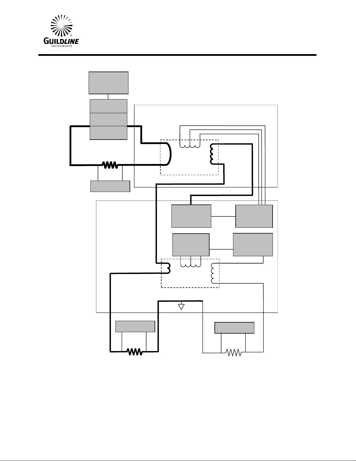
1.4. PRINCIPLE OF OPERATION.......................................................................................................................1-2
2. INSTALLATION ........................................................................................................2-1
2.1. PRELIMINARIES............................................................................................................................................2-1
2.1.1. Unpacking.......................................................................................................................................................2-1
2.1.2. Power Voltage Selection ................................................................................................................................2-1
2.1.3. Fuse Replacement...........................................................................................................................................2-2
2.1.4. Setup and Power On.......................................................................................................................................2-3
2.2. INCOMING INSPECTION.............................................................................................................................2-5
2.3. 6624CT-3000 FRONT VIEW...........................................................................................................................2-7
2.3.1. Power..............................................................................................................................................................2-7
2.3.2. Balance ...........................................................................................................................................................2-7
2.3.3. 3 A Burden......................................................................................................................................................2-7
2.3.4. 150 mA Burden ..............................................................................................................................................2-8
2.3.5. Range Switch..................................................................................................................................................2-8
2.4. 6624CT-3000 REAR VIEW.............................................................................................................................2-9
2.4.1. Line Input Connectors....................................................................................................................................2-9
2.4.2. Control Connector ..........................................................................................................................................2-9
2.4.3. DCCT-3000 Connector..................................................................................................................................2-9
2.4.4. CS1000 Connector..........................................................................................................................................2-9
3. QUICK MEASUREMENT GUIDE.............................................................................3-1
3.1. MEASUREMENT OPERATION GUIDE.....................................................................................................3-1
3.1.1. Current Measurement all Ranges...................................................................................................................3-1
3.1.2. Calculation of the Unknown Shunt Resistance..............................................................................................3-3
3.1.3. Recommended Test Setup Limits and Precautions for the 6624CT-3000 ....................................................3-3
3.1.4. Checks and Precautions..................................................................................................................................3-3
4. VERIFICATION AND CALIBRATION.......................................................................4-1
4.1. RATIO ACCURACY VERIFICATION........................................................................................................4-1
4.1.1. Purpose ...........................................................................................................................................................4-1

OM6624CT-3000-5-00
11 May, 2016
ii
4.2. TEST EQUIPMENT REQUIRED..................................................................................................................4-1
4.3. PROCEDURE....................................................................................................................................................4-2
4.3.1. Preliminary Connections to the 6624CT-3000 ..............................................................................................4-2
4.3.2. Measurement of the Potentials on the Resistors.............................................................................................4-2
4.3.3. Calculation of the Range Ratios.....................................................................................................................4-3
5. TROUBLESHOOTING AND MAINTENANCE .........................................................5-1
5.1. INTRODUCTION.............................................................................................................................................5-1
5.1.1. Model 6623A-3S Controller Fault Indications ..............................................................................................5-1
5.1.2. Maintenance....................................................................................................................................................5-1
6. APPENDICES...........................................................................................................6-1
6.1. GENERAL SPECIFICATIONS......................................................................................................................6-1
6.2. GENERAL SPECIFICATIONS (continued).................................................................................................6-2

OM6624CT-3000-5-00
11 May, 2016
iii
LIST OF FIGURES
FIGURE 1-1 : MODEL 6624CT-3000 BLOCK DIAGRAM......................................................................................1-3
FIGURE 2-1 : LINE VOLTAGE SELECTOR.............................................................................................................2-2
FIGURE 2-2 : 6624CT-3000 FRONT VIEW................................................................................................................2-7
FIGURE 2-3 : 6624CT-3000 REAR VIEW...................................................................................................................2-9
FIGURE 2-4 : 6624CT-3000 CONNECTIONS..........................................................................................................2-10
FIGURE 2-5 : 6624CT-3000 WITH PRIMARY CURRENT SHUNT CONNECTIONS.....................................2-11

OM6624CT-3000-5-00
11 May, 2016
iv
LIST OF TABLES
TABLE 2-1 : FUSE RATINGS.......................................................................................................................................2-2
TABLE 3-1 : 6624CT-3000 TEST SETUPS..................................................................................................................3-4
TABLE 6-1 : GENERAL SPECIFICATIONS.............................................................................................................6-1
TABLE 6-2 : GENERAL SPECIFICATIONS (CONTINUED).................................................................................6-2

Section 1
OM6624CT-3000-5-00
11 May, 2016
1-1
1. INTRODUCTION
1.1. SCOPE
This document describes the installation, operation, specifications, maintenance and verification of
the 6624CT-3000 High Current DC Transformer. Precautions associated with high current
connections and measurements are provided for purposes of user safety and reliability.
1.2. GENERAL DESCRIPTION
The Model 6624CT-3000 High Current DC Transformer is designed to measure Direct Currents up
to a magnitude of 3000 amperes. The 6624CT-3000 is designed to be used with any current source;
however the 6624CT-3000 has additional built-in protection and safety features when used with
Guildline equipment. Specifically these protection and safety features are activated when the
6624CT-3000 is used in conjunction with Guildline CS1000 Current Sources and the 66259
Extender Control Unit; or when used with a Guildline 6622A DCC Bridge and the 6623A High
Current Range Extender. The direct current transformer is designed with an open window to pass
through a cable, set of cables, or buss bar that carry the current to be measured. The 6624CT-3000
High Current DC Transformer produces an output current that varies directly with the input current
in three ranges. By the connection of a reference shunt burden on one of the output terminals the
primary current can be deduced from the measured voltage on the reference shunt.
Switch selectable secondary windings provide transformation ratios of 100:1, 500:1, and 1,000:1;
and allow for measurements to be performed up to a maximum of 3000 amperes. The full scale
output range of 3 A is provided at a pair of binding post terminals on the front panel of the control
chassis. Three primary current ranges are provided, 300 A, 1500 A and 3000 A. A second pair of
binding post terminals is provided which provides an additional 20:1 reduction in the secondary
current such that a full scale output of 0.15 A is available for each primary range. A reference shunt
of 1 ohm or less is recommended for use as a burden.
The 6624CT-3000 High Current DC Transformer includes a 6623A-3S DC Current Transformer
Controller which provides for the modulation and demodulation of the DC flux in the Current
Transformer Unit. The 6623A-3S is normally mounted close to the current transformer through a
1.5m 12 conductor cable. The 6623A-3S also provides connections between CS1000 Current
Source Units and a Model 66259 Extender Control Unit or a 6622A DCC Bridge. The Model
66259 in combination with the CS1000 Current Source Units provides for primary DC currents
from 3 to 3000 A. The 6624CT-3000 High Current DC Transformer is pre-wired and configured
for operation at nominal power line voltages of 100, 120, 220 or 240 VAC.
All necessary interconnections for the control of the Guildline 6623A current source, the 6623A-3S
DC Current Transformer Controller and the 6624CT-3000 High Current DC Transformer are
provided such that no hardware reconfiguration is required over the full range of operation other
than the connection of the output current terminal to an appropriate reference burden.

Section 1
OM6624CT-3000-5-00
11 May, 2016
1-2
1.3. OVERVIEW
The Model 6624CT-3000 High Current DC Transformer is a precision, fixed ratio, direct current
transformer based on the principle of the direct current comparator. Figure 1-1 illustrates the
instrument circuits in block diagram form. Connections to the Guildline CS1000 Current Source
Units and the Model 66259 Extender Control Unit are shown when it is desired to use these as the
current source. The precision programmable electronically switched 6623A current source is
controlled using the Model 66259 Extender Control Unit. The 6623A-3S DC Current Transformer
Controller is connected to the Current Transformer Unit with a twelve conductor cable with circular
connectors. The 6623A-3S also has two other connections for the Model 66259 Extender Control
Unit and the CS1000 current sources.
No adjustments of the 6624CT-3000 High Current DC Transformer are required for proper
operation, but the correct range must be manually selected on the Current Transformer Unit for one
of three specific full scale current ranges. Three full scale ranges are provided; 3000 A, 1500 A and
300 A with transformation ratios of 1000:1, 500:1 and 100:1 respectively.
1.4. PRINCIPLE OF OPERATION
The Direct Current Comparator is a multiple winding toroidal transformer device shown in Figure
1-1 in which the primary window carries the direct current input. Modulator and detector windings
are used for the detection of DC flux in the core. Switch selectable secondary windings of 100, 500
and 1000 turns provide the means to balance the ampere-turns in the transformer core. When the
primary and secondary ampere-turns are equal and opposite there is zero resultant DC flux in the
core. This balance condition can be detected by the flux detector circuit. The DC output of the
detector is proportional to ampere-turn imbalance. The presence of DC flux in the core due to
primary-secondary ampere-turns unbalance is indicated by the detector in both magnitude and
polarity.
The peak detector drives a servo circuit to provide correction current which maintains ampere-turn
balance in the core such that the ratio of input and output currents is exactly 100:1, 500:1 or 1000:1
depending on which range of operation is selected. The Model 66259 Extender Control Unit
provides a drive signal to the CS1000 programmable current sources as to allow test currents from
+/- 3 A to +/- 3000 A to be realized. This current is normally directed to the primary window of the
toroidal transformer. Refer to the 66259 Operation Manual for a description of the current source
control and safety features.
Note that the 6624CT-3000 can be operated with a non-Guildline current source. In this
configuration no connections are required to the 66259 Extender Control Unit or to the CS1000
Programmable Current Sources.

Section 1
OM6624CT-3000-5-00
11 May, 2016
1-3
Figure 1-1 : Model 6624CT-3000 Block Diagram
Voltmeter
P1
P2
C1
C2
P1
P2
C1
C2
Current
Comparator
Toroid 3A
1000T
Ns
50T
Servo Amplifier
Demodulator
Slave PSU
Flux Detector
Magnetic
Modulator
6624CT-3000 Current Transformer
Current
Comparator
Toroid 3000A
1000T
500T (switchable)
100T
Ns
Servo Amplifier
Demodulator
Slave PSU
6623A-3S
Control Unit
1000A
Current Source
1000A
Current Source
1000A
Current Source
Nx
1T
P2
P1
C2
C1
Voltmeter
Voltmeter
Flux Detector
Magnetic
Modulator
66259
Programmable
Current Drive

Section 2
OM6624CT-3000-5-00
11 May, 2016
2-1
2. INSTALLATION
2.1. PRELIMINARIES
Note that the Model 6624CT-3000 High Current DC Transformer includes a separate 6623A-3S
DC Current Transformer Control Unit. The 6624CT-3000 High Current DC Transformer is
connected to the 6623A-3S DC Current Transformer Control Unit with a 1.5 m cable. The 6623A-
3S is normally shipped set for 240 Volt, 50/60 Hz operation. If necessary the 6623A-3S can be set
for 100, 120 or 220 Volt, 50/60 Hz operation. The Model CS1000 Current Source Units and the
Model 66259 Extender Control Unit are options for providing a suitable current source for use with
the 6624CT-3000 system.
2.1.1. Unpacking
a. Remove the 6624CT-3000 High Current DC Transformer and the other items from
the shipping container to a suitable location.
b. The following items are included along with the current transformer and control
units.
i. Operation Manual (OM6624CT-3000)
ii. Two Spare Fuses 1 A, (T) (GPN 099-21000)
iii. Two Spare Fuses 2 A, (T) (GPN 099-22000)
iv. Three SCW Leads, 2 m (GPN 20236.04.02)
v. One 12 conductor 1.5 m connection cable (GPN# 31482-01-21)
vi. AC Line Cord (GPN# 250-04030)
vii. Two Shorting Links (GPN# 225-02090)
viii. Termination Connector (GPN# 31061-02-09)
ix. Extender Cable 2.0 m (GPN# 20212.04.02)
2.1.2. Power Voltage Selection
The 6623A-3S DC Current Transformer Controller Unit is shipped with the line input
voltage set to 240 V. The line input selector must be set to the correct line voltage and the
correct fuse must be installed before power is applied to the instrument. The settings
available are 100 V, 120 V, 220 V, and 240 V. Figure 2-1 details the line input voltage
selector settings and fuse requirements.
Where the molded plug on the line cord supplied with the instrument does not match the
local power outlet socket, the plug can be removed and replaced with one that does fit the
local service. The plug should be re-wired as follows:
Brown wire - Line input
Blue wire - Neutral input
Green/Yellow - Ground (safety)

Section 2
OM6624CT-3000-5-00
11 May, 2016
2-2
2.1.3. Fuse Replacement
Only fuses with specified current rating type should be used for replacement if necessary.
See Table 2-1.
FUSES (TIME DELAY TYPE)
100 V
120 V
220 V
240 V
2 A, 250 V, (T)
2 A, 250 V, (T)
1 A, 250 V, (T)
1 A, 250 V, (T)
Table 2-1 : Fuse Ratings
100V
120V
220V
240V
100V
120V
220V
240V
EXPOSE LINE SELECTOR SLIDER
REMOVE SELECTOR (120V SHOWN)
PRY HERE TO REMOVE COVER
ROTATE SELECTOR AND REPOSITION
SLIDER TO DESIRED LINE INPUT
(240V SHOWN) AND REINSERT
REPLACE COVER
DISCONNECT POWER
Figure 2-1 : Line Voltage Selector

Section 2
OM6624CT-3000-5-00
11 May, 2016
2-3
2.1.4. Setup and Power On
a. Refer to Figure 2-4 for a typical system setup for current and shunt measurements.
b. Verify that the power switch is off on the 6623A-3S DC Current Transformer
Controller.
c. Remove any excess packing material from around the front and back panels that is
provided for shipping purposes only. Verify that the Line Voltage to be used
matches the Line Voltage setting marked on the back panel of the 6623A-3S DC
Current Transformer Controller. If the Line Voltage to be used does not match, see
section 2.1.3. to set the line voltage selector to the proper line voltage and select the
correct fuse.
d. Connect the 6623A-3S Control Unit to the 6624CT-3000 High Current DC
Transformer Unit using the 12 conductor cable provided. One end is to be connected
to the circular connector on the back panel of the 6623A-3S marked 'DCCT-3000'
and the other end to the circular connector on the back panel of the 6624CT-3000
marked 'CONTROL'.
e. Set the Range Switch on the front panel of the 6624CT-3000 unit to '1000:1, 3000A
FS' range.
f. If it is to be utilized, connect the Model 66259 Extender Control Unit to the circular
connector on the back panel of the 6623A-3S marked 'CONTROL'. The 66259
Extender Control Unit should have the cable attached to the connector marked
'EXTENDER'. Ensure that a termination plug is connected to the connector marked
'BRIDGE' on the 66259 unit. Note that when the Model 66259 is not used, a
termination plug (GPN# 31061-02-09) must be connected to the 'CONTROL'
connector on the 6623A-3S.
g. If it is to be utilized, connect one end of a 7 conductor cable, (GPN# 20212.04.02)
with circular connectors to the circular connector on the back panel of the 6623A-3S
marked 'CS1000' and the other end to the first CS1000 Current Source Unit
connector marked 'INPUT'. Ensure that a termination plug, (GPN# 31061-02-09) is
connected to the 'OUTPUT' connector on the last CS1000 unit connected to the
system. Also ensure each CS1000 unit is interconnected from 'OUTPUT' to 'INPUT'
with short 7 conductor cables.
Note: Where more than three CS1000 Current Source Units are connected only the
first three units can be turned on for use in the 6624CT-3000 system. Otherwise a
serious over-current condition may result that may damage the 6623A-3S Control
Unit.
When a non-Guildline current source is being used make sure that the supplied
current is less than or equal to 3000 A. Otherwise a serious over-current condition
may result that may damage the 6623A-3S Control Unit.

Section 2
OM6624CT-3000-5-00
11 May, 2016
2-4
h. Connect a suitable reference burden or shunt resistance to one of the 6623A-3S
terminals marked '3 A BURDEN' or '150 mA BURDEN'. A shorting link must be
installed across the terminals that are not being used. Normally a 1 ohm or less DC
reference shunt is used that has a known calibrated resistance at the full scale current
of 3 A and 0.15 A.
i. Connect the input power cord from the 6623A-3S to the AC power outlet.
j. Turn on the power switch to the 6623A-3S Control Unit. You should see the red
'POWER' indicator on the front panel light up and that the meter indicator moves to
the right or left side initially then returns to the centre line within the graduation
lines of the meter. A small offset is a satisfactory indication that a balance condition
exists on the 6624CT-3000 Transformer Unit.
k. If it is to be utilized, connect the line cord of the 66259 Extender Control Unit to an
AC power outlet and turn on the unit. Note that the 66259 Operation Manual should
be referenced for proper operation and control of the CS1000 Current Sources. The
66259 Extender Control Unit must be properly configured for the number of
CS1000 units employed.
l. If it is to be utilized, connect the 'OUT+' buss of the CS1000 units through the
window of the 6624CT-3000 going from left to right looking from the front panel
with suitable heavy current cables. Continue to connect the other end of the cables
across a shunt that is to be measured or to the 'OUT-' buss of the CS1000 units such
that a complete circuit is provided. Where the CS1000 units are not used a separate
current source must be setup to supply a test current through the window of the
6624CT-3000 High Current DC Transformer Unit.
m. If it is to be utilized, turn on the power switch to the CS1000 Current Source Units.
You should see the red 'POWER' indicator on the front panels light up. The yellow
fault indicators on the CS1000 modules will light 'ON' for about 6 seconds then
remain off.
n. There should not be any yellow 'Fault' indicators remaining on the connected
CS1000 Current Sources. There is a set of 7 yellow indicators visible within the
front grill which indicate when a fault is experienced in any of the 7 internal 150 A
current source modules. If some of these should remain on, the power can be re-
cycled off and on a number of times to clear the fault.
o. Up to three CS1000 Current Source Units may be utilized. If more than three units
are available power on only the first three units and leave the others turned off.
Where the CS1000 units are not used a separate current source is required.
p. The system should now be ready to use as a current source and current measurement
system. The potential on the reference burden will be a direct ratio of the high
current being sourced from the current source depending on the range selection of
the 6624CT-3000 High Current DC Transformer. When set for a range of '1000:1,

Section 2
OM6624CT-3000-5-00
11 May, 2016
2-5
3000 A FS' the output current on the 3 A reference burden will be a maximum of
3 A when a 3000 A current is selected.
Note: Always turn the Current Sources on LAST after the 6623A-3S Control Unit
and the 66259 Extender Control Unit are turned on. And, always turn the Current
Source off FIRST before turning off the 6623A-3S or the 66259. Never turn the
Current Source off or on while a measurement is in progress.
2.2. INCOMING INSPECTION
If a 66259 Extender Control Unit is being used, a specific current program profile must be entered
into the 66259 Extender Control Unit before measurements can be set up and initiated. Where the
66259 Extender Control Unit and the 6624CT-3000 High Current DC Transformer are shipped at
the same time from the factory, a proper profile for three CS1000 Current Source Units is already
entered and a Summary of Coefficients is supplied with the system. Otherwise a profile will need to
be configured as specified in the 66259 Operation Manual.
If no faults are displayed during power up then proceed to measure a selected test current. A 1 ohm
or less Reference Shunt, such as a Guildline 9230A-10-1 must be installed on the 6623A-3S front
panel terminals marked '3 A BURDEN' and a shorting link on the 6623A-3S terminals marked '150
mA BURDEN'. Note that for proper setup and operation of the 66259 refer to the 66259 Operation
Manual. Refer to Figure 2-4 for interconnection details. Using the measurement set up procedure
below:
Step 1) Check the connection of components of the system in the following order:
- The 6624CT-3000 Transformer Unit is connected to the 6623A-3S with the
12 conductor cable.
- The 6624CT-3000 is set to the '1000:1, 3000 A' range.
- If it is to be utilized, the 66259 Extender Control Unit is connected to the
6623A-3S 'CONTROL' connector and a termination plug is installed at the
'BRIDGE' connector.
- If it is to be utilized, the CS1000 Current Source(s) input is connected to the
6623A-3S 'CS1000' connector. Where the CS1000 is not used, a separate
current source is required.
- A 1 ohm shunt is connected to the 6623A-3S front panel terminals marked
'3 A BURDEN'.
- A high accuracy Digital Volt Meter is connected to the potential terminals of
the 1 ohm reference shunt, set for a measurement on the 1 Volt range and
any thermal EMF offset removed.
- A shorting link is installed at the 6623A-3S terminals marked '150 mA
BURDEN'.

Section 2
OM6624CT-3000-5-00
11 May, 2016
2-6
Step 2) Turn on the components of the system in the following order:
-The 6623A-3S Control Unit.
-The DVM.
-The 66259 Extender Control Unit if implemented.
-The CS1000 Current Sources, if implemented, up to three units only; or the
separate current source.
Step 3) Zero the DVM reading then set a nominal positive test current of 100 A.
Step 4) Observe and record the voltage on the potential terminals of the reference shunt as
displayed on the DVM after the test current has stabilized for a few minutes.
Observe that the balance meter on the front panel returns to and remains near the
centre line within the graduation lines of the meter. A small offset is a satisfactory
indication that a balance condition exits on the 6624CT-3000 Transformer Unit.
Note that an averaging function on the DVM will be required to smooth out small
variations in the current source output.
Step 5) Set a negative nominal test current of 100 A.
Step 6) Observe and record the voltage on the potential terminals as displayed on the DVM
after the test current has stabilized for a few minutes.
Step 7) Divide the absolute value of the mean of the two voltages, and divide the result by
the known calibrated resistance value of the reference shunt.
Step 8) Multiply the result by the range factor of 1000 and check that the result is within
0.1 % of the 100 A test current requested.
Note: The test should execute with no measurement errors indicated. This is not the 6624CT-
3000 full rated accuracy but serves as a functional test for the purposes of determining the
instrument has been received in proper working order.
Note: It is recommended to keep the CS1000 modules powered off when the instrument is not
in use for extended periods of time. Always turn the CS1000 modules off first then the
remaining components.

Section 2
OM6624CT-3000-5-00
11 May, 2016
2-7
2.3. 6624CT-3000 FRONT VIEW
Figure 2-2 : 6624CT-3000 Front View
2.3.1. Power
The Power indicator is lighted when the AC power is applied to the units and the power
switches on the rear panels are 'ON'. The power indicator on the 6623A-3S may dim if a
large comparator imbalance condition exists. In this case the current source and the 6623A-
3S should be turned off.
2.3.2. Balance
The Balance indicator or meter on the 6623A-3S DC Current Transformer Controller will
be pegged to the left or the right when a fault condition in the servo amplifier of the current
comparator module is detected indicating a comparator imbalance condition may exist or
there is an open circuit at one of the output terminals.
A small offset is a satisfactory indication that a balance condition exits on the DCCT-3000
Transformer Unit.
Note: Do not operate the system if the meter remains pegged off-scale as this may
damage the controller electronics. Turn off the current source and the 6623A-3S and
correct any connection problems or range selection errors.
2.3.3. 3 A Burden
The 3 A Burden binding post terminals are provided for connection of a suitable reference
shunt. If a shunt is not used a shorting link must be installed for proper operation. The full
scale output is 3 A.

Section 2
OM6624CT-3000-5-00
11 May, 2016
2-8
2.3.4. 150 mA Burden
The 150 mA Burden binding post terminals are provided for connection of a suitable
reference shunt. If a shunt is not used a shorting link must be installed for proper operation.
The full scale output is 150 mA.
2.3.5. Range Switch
The Range Switch located on the 6624CT-3000 High Current DC Transformer allows for
selection of 1000:1, 500:1 and 100:1 current transformation ratios with full scale values of
3000, 1500 and 300 A respectively.

Section 2
OM6624CT-3000-5-00
11 May, 2016
2-9
2.4. 6624CT-3000 REAR VIEW
Figure 2-3 : 6624CT-3000 Rear View
2.4.1. Line Input Connectors
The Line Input Connectors are a combination of a 3-prong AC standard male IEC
connector, and an ON/OFF switch. The 6623A-3S Controller has a fused line input with
access for fuse replacement. The CS1000’s have a 15 A circuit breaker as part of the line
input connector. The line input connectors accommodate nominal voltages of 208 to 240 V.
2.4.2. Control Connector
The Control Connector of the 6623A-3S is a 7 pin circular connector which is used to
connect the Model 66259 Control Unit. The 66259 provides program signals for the
CS1000 Current Sources and the 6623A-3S tracking of the current comparator.
2.4.3. DCCT-3000 Connector
The DCCT-3000 Connector is a 16 pin circular connector which is used to connect the
necessary signals to the Model 6624CT-3000 Current Transformer 'CONTROL' connector.
Only 12 of the pin connections are utilized.
2.4.4. CS1000 Connector
The CS1000 Connector is a 7 pin circular connector which is used to connect the necessary
signals to the first 1000A current source 'INPUT' connector. The 'OUPUT' connector of first
CS1000 is connected to the 'INPUT' of the next unit and then to the third unit.
Note that the 'OUTPUT' of the last or upper CS1000 module must have a termination
plug, (GPN 31061-02-09) installed for proper operation.

Section 2
OM6624CT-3000-5-00
11 May, 2016
2-10
Figure 2-4 : 6624CT-3000 Connections
P2
P1
C2
C1
Voltmeter on
REF Shunt
Current Source

Section 2
OM6624CT-3000-5-00
11 May, 2016
2-11
Figure 2-5 : 6624CT-3000 with Primary Current Shunt Connections
P1
P2
C1
C2
Voltmeter on
DUT Shunt
P2
P1
C2
C1
Voltmeter on
REF Shunt
Current Source
Table of contents
Popular Transformer manuals by other brands

Siemens
Siemens MICROMASTER 430 Maintenance Instruction

RCF
RCF TD60 user manual

AquaCal AutoPilot
AquaCal AutoPilot ST-100-12 installation guide

MuxLab
MuxLab Quad Audio Balun Quick installation guide

Jobsite
Jobsite BT-V Installation and user guide

Larson Electronics
Larson Electronics DCP-25-3XDP-6FT instruction manual