Guldmann DH 2000 User manual

GB . . . . . . .DH 2000
Vers. 1.00

2
© Guldmann GB-896/08/08 • # 900662
DH 2000, Ceiling - mounted hoist
Item nos:
12075 - 000
12075 - 100
1.00.........PurposeandUse..............................................3
1.01.........Manufacturer..................................................3
1.02 . . . . . . . . . Purpose and Use of Hoist . . . . . . . . . . . . . . . . . . . . . . . . . . . . . . . . . . . . . . . . 3
1.03.........Important/warning .............................................4
1.04.........SlingSafety...................................................5
1.05 . . . . . . . . . Unpacking and preparation of the hoist. . . . . . . . . . . . . . . . . . . . . . . . . . . . . . 5
1.06 . . . . . . . . . Mounting of charging station.. . . . . . . . . . . . . . . . . . . . . . . . . . . . . . . . . . . . . . 5
1.07 . . . . . . . . . Mounting of charging station in the traverse rail system. . . . . . . . . . . . . . . . . 6
1.08.........Assemblingbeforeuse ..........................................7
1.09.........Swing-kit.....................................................8
2.00.........DescriptionofFunctions .......................................9
2.01.........Pictograms/labels .............................................9
2.02.........Operatingthehoist .............................................9
2.03.........Safetyfunctions...............................................10
2.04 . . . . . . . . . Recharging / connecting the hoist . . . . . . . . . . . . . . . . . . . . . . . . . . . . . . . . 10
2.05 . . . . . . . . . Connection of Charging station . . . . . . . . . . . . . . . . . . . . . . . . . . . . . . . . . . . 10
2.06.........Accessories..................................................11
3.00.........Dismantling&Transport.......................................12
3.01.........Dismantlingthehoist ..........................................12
3.02 . . . . . . . . . How to transport the hoist ?. . . . . . . . . . . . . . . . . . . . . . . . . . . . . . . . . . . . . . 12
3.03 . . . . . . . . . How to package the hoist for transport ?. . . . . . . . . . . . . . . . . . . . . . . . . . . . 12
4.00 . . . . . . . . . Maintenance and storage . . . . . . . . . . . . . . . . . . . . . . . . . . . . . . . . . . . . . . 12
4.01.........Cleaningthehoist.............................................12
4.02.........Storingthehoist ..............................................12
4.03.........Long-termstorage.............................................13
4.04 . . . . . . . . . How to prevent / avoid corrosion ? . . . . . . . . . . . . . . . . . . . . . . . . . . . . . . . . 13
4.05 . . . . . . . . . Maintenance which should be carried out by the owner? . . . . . . . . . . . . . . . 13
5.00.........ServiceandLifeSpan ........................................13
5.01 . . . . . . . . . Life span and servicing of hoist . . . . . . . . . . . . . . . . . . . . . . . . . . . . . . . . . . 13
5.02.........Batteryandfuses..............................................13
5.03.........Servicecheck-Allround ........................................14
5.04.........TroubleShooting..............................................15
6.00 . . . . . . . . . Technical Specications ......................................15

3
1.00 Purpose and Use
1.01 Manufacturer
V. Guldmann A/S.
Graham Bells Vej 23A
DK – 8200 Århus N
Tel. + 45 8741 3100
Fax. + 45 8741 3131
1.02 Purpose and Use of Hoist
Purpose
DH 2000 is a lifting module of the Guldmann Ceiling-Mounted
Lifting Systems. DH 2000 is suitable in all Guldmann rail systems, both single
track, room-covering, and combined rail systems.
DH 2000 is developped for use in private homes, insitutions, hospitals, riding
schools, and swimming pools, where it offers
full exibility for lifting, transferring, and transporting of elderly
and disabled persons.
Requirements
The instruction that Guldmann offers all custumers when ordering a DH 2000,
has been received.
When a hoist is used in an institution or in the home care service, the
assumption is that it will be operated by qualied staff.
Use slings with 4-6 lifting straps designed for use with hooks of min. Ø 8 mm.
Lifting to and from a sitting position
When lifting from e.g. a wheelchair, move DH 2000 towards the person to be
lifted. The lifting hanger should be level with the chest and positioned above
the middle of the thigh.
Position lifting hanger parallel to the user’s shoulders. Now t the lifting sling
to the lifting hanger. For instructions on how to t the sling, see the section
entitled “Fitting the sling”.
Lifting to and from a lying position in bed
The lifting hanger is placed right over the person. The lifting hanger should
be parallel with the person’s shoulders. Now t the lifting sling to the lifting
hanger. For instructions on how to t the sling, see section entitled “Fitting the
sling”.
Working with DH 2000
As the DH 2000 does not require any special space or power consumption
and as it is easy to move around in the rail system, only the user’s functional
level and the carer’s working technique need to be considered.
Lift the user claer of the surface and continue transferring at this height.
© Guldmann GB-896/08/08 • # 900662

4
Fitting the sling
Hook the top set of straps (from the back) to the hooks facing the user. Hook
the lower set of straps (from the legs) to the hooks facing away from the user.
From a chair, wheelchair or other sitting positions
Place lifting sling behind user’s back e.g. between the back of the chair and
the user’s back.
The suspension strap marking the size of the
sling, for instance M, indicates the centre of the
sling and should follow the spine.
The green, blue or red type marking bands run
parallel to the spine.
The user should not sit on the sling.
Bring the leg straps along the outer thigh and
then under the thigh between the back of the
knee and the hip. Now cross the leg straps in
front of the user. All four straps are now ready
to be mounted to the lifting hanger.
Lying position in bed, on a mattress or on
the oor
Turn the user on his side. Place the high back
sling so that its upper edge is ush with the top
of the user’s head. Put the sling on the user
so that the coloured bands run parallel to the
spine. Turn the user on his back and pull the
sling out. Bring the leg straps under the thigh
and cross them over. All four straps are now
ready to be mounted to the lifting hooks.
If in doubt about how to use the sling, please contact your supplier.
Guldmann A/S cannot be rendered liable for inadequate anchoring resulting
from incorrect estimation of mounting conditions.
Guldmann cannot rendered liable for defects or accidents due to incorrect
tment or assesment of slings.
1.03 Important / warning
Read the user manual fully before using the DH 2000.
Do not exceed the max. load of 175 kg.
If accessories are used that are marked with a lower load capacity than 175
kg, the lowest load capacity decides the maximum load of the DH2000.
Use the hoist to lift persons only.
Do not use DH 2000 where there is a risk of considerable amounts of water
continuously coming into direct contact with the hoist.
If the DH 2000 shows defects during use, operation must be discontinued.
Contact your local Guldmann representative for a possible repair
The DH 2000 must not be used witout the extension strap if the distance bet-
ween rail and oor exceeds 3 metres.
The string of the emergency lowering unit should be adapted to the reach of
the user.
•
•
•
•
•
•
•
•
© Guldmann GB-896/08/08 • # 900662

5
1.04 Sling Safety
Only CE-marked slings with a lifting capacity corresponding to or higher than
the lifting capacity of the DH 2000 are to be used.
The lifting straps must be suitable for hooks with a diameter of 8 mm. The lif-
ting straps must be designed for use with a four-point horizontal lifting hanger.
Guldmann cannot be rendered liable for defects and accidents, due to use of
a sling manufactured by others.
1.05 Unpacking and preparation of the hoist
Visual check of hoist:
Should the packaging be damaged on receipt, each part of the hoist must be
carefully examined for visible defects or deciencies. In case of suspected
damage, do not use the hoist until authorised by qualied service staff or the
Guldmann Service Team.
Parts list:
Pos.
1. DH 2000
2. Hand switch
3. Lifting hanger, if delivered
1.06 Mounting of charging station.
Always position the charging station together with an end stop. Check that the
current receiver on the hoist / trolley for traverse rail is turned the right way so
that it faces the conductor housing.
Make a mark on the rail to indicate where
the end stop is to be positioned.
B Loosen the end stop and slide it up the rail.
Pull the wire of the conductor housing out
of the rail and position the rear end of the
conductor housing opposite the mark.
C Remove the cover lm from the tape on the
conductor housing and push one side of the
conductor housing into the rail.
D Push the other side of the conductor hou-
sing into the rail so that it rests on the bot-
tom of the rail. Check that the conductor
housing is positioned opposite the mark.
E Push the conductor housing into position in
the rail. Push right at the side of the condu-
ctor housing in order to avoid deforming it.
Give the conductor housing a press to
ensure that the tape is in fully contact with
the rail.
E.D.C.
F.
B.
A
.
© Guldmann GB-896/08/08 • # 900662

6
Slide the end stop back to the mark. Unscrew the screw (1) next to the rub-
ber knob of the end stop and t the spring retainer (2) into the opening of the
rail undeneath the end stop. The opening of the spring retainer must face the
hoist. The foam rubber disc (3) must be positioned at the bottom end of the
spring retainer (4) behind the screw. Tighten the end stop.
Connect the conductor housing to the charger and check the function.
The positioning of the conductor housing could be marked by means of the
enclosed labels with charging symbols.
1.07 Mounting of charging station in the traverse rail system.
When charging in the traverse
rail system, two conductor hou-
sings, one for the traverse rail
and one for the parallel rail are
employed. Furthermore, one
current receiver is employed in
addition to the current receiver on the hoist.
The above mounting instructions apply for the mounting of the conductor hou-
sing in connection with trolley for traverse rail. However, no spring retainer is
to be mounted.
Before mounting the trolleys for traverse rail, position the current receiver on
one of the trolleys for traverse rail and make sure that it will face the chosen
position of the conductor housing.
Fit the current receiver to the hanger at the end of the trolley and push it into
position in the eye of the hanger. The solderings of the current receiver must
turn away from the trolley.
Check that the wire is secured in the hooks placed at the bottom of the
current receiver.
After mounting the traverse
rail, mount the conductor
housing of the hoist as shown
in the instructions, and con-
nect it to the current receiver
on the trolley for traverse rail.
The marked wire is the + con-
ductor. (The + conductor of
the conductor housing is con-
nected to the + conductor of
the current receiver)
Stick the wire underneath the trolley for traverse rail by means of double
sided adhesive tape.
Connect the conductor housing to the charger and check the function.
The positioning of the conductor housing could be marked by means of the
enclosed labels with charging symbols.
If service/repair should be necessary, the conductor housing and charging
station for the room-covering system can be dismounted and exchanged
without dismounting the rail system. For servicing of the current receiver it is
necessary to remove the hoist and/or the travelling trolley from the rail.
© Guldmann GB-896/08/08 • # 900662

7
1.08 Assembling before use
Place the DH 2000 lifting unit in
the rail prior to mounting the lifting
hanger. The Guldmann lifting hanger
model 21170 or 21190 is mounted
on the lifting strap as shown on the
drawings below.
For use with DH 2000, the standard
liftinghanger is model 21170.
Loosen the pointed screws (4) with
the 1.5 mm Allen key to pull out the
axle journal (3) and the cylinder
sleeve (1). Insert the cylinder sleeve
in the lifting strap (2) and mount the
lifting hanger(5).
For use with DH 2000 with the oval
hook, the lifting hanger is model
21190.
Loosen the screw, remove the pipe and mount the lifting hanger.
Reposition the pipe and tighten the screw.
The pipe is mounted as shown below
Please make sure that the screw is correctly
xed and fastened after the installation.
Bath chair, bath stretcher, or horizontal lifting support are mounted direct on
to the oval hook of the lifting strap, by means of a snap hook with a swiveling
safety. The hand control is connected to the plug on the bottom of the lifting
module, as shown on the sketch.
DH 2000 is now ready for use in the Guldmann rail systems.
© Guldmann GB-896/08/08 • # 900662

8
1.09 Swing - kit.
1. Place the two hoists as close to each other
as possible.
Mount the lifting hanger on the hook of
hoist B.
2. Unroll the unloaded strap of the hoist A
until it can be hooked onto the oval hook of
the lifting hanger.
3. Continue to unroll a little further the lifting
strap of the hoist B and then wind up the
lifting strap of hoist A.
Once the transfer from one room to the
other is carried out, one of the lifting straps
is unloaded, hoist B.
4. Disconnect the unloaded strap from the
lifting hanger. Wind up the lifting strap into
the hoist B, where it remains until the hook
is going to be used again.
5. Move the lifting hanger in hoist A up to
correct working height and the transfer
through the door is completed.
A B
© Guldmann GB-896/08/08 • # 900662

9
2.00 Description of Functions
2.01 Pictograms / labels
Pictograms printed on bottom of the DH 2000
1. Charging 2.Hand- 3.Emergency 4.Emergency
indicator control stop lowering.
2.02 Operating the hoist
Hand switch and indicator lamp
DH 2000 switches on automatically when pressing one of the keys
of the hand control.
The lamp turns green when the hoist is switched on.
The hoist switches off automatically approx. 1 minute after use.
DH 2000 will only function when the lifting hanger is mounted on
the lifting strap.
Lifting and lowering is activated by pressing and of the hand con-
trol.
Transport / Transferring along the rail system
Transferring and transport of the DH 2000 along the rail is carried out manu-
ally by the carer
The transverse drive motor
DH 2000 can be provided with a transverse drive motor, which can be build
into the hoist
The transverse drive motor is activated by pressing or of the hand control.
DH 2000 with transverse drive motor can also be transported manually along
the rail system, when the hoist is switched on and are not activated.
3
4
/
0
3
4
/
0
3
4
/
0
3
4
/
0
3
4
/
0
3
4
/
0
3
4
/
0
3
4
/
0
© Guldmann GB-896/08/08 • # 900662

10
2.03 Safety functions
Important.
Only use the emergency stop and emergency lowering functions in emergen-
cies. Should it be necessary to apply the emergency / safety functions, the
supplier must be contacted prior to using the hoist again.
Description of the emergency stop function
If during operation the DH 2000 should not react on the functions of the hand
control, the lifting/lowering can be interrupted by pulling the string marked
“STOP”. The DH 2000 is not ready for operation again, until the emergency
stop has been pushed back into the hoist again.
Description of the emergency lowering function
If the DH 2000 fails to operate by the hand control, the emergency lowe-
ring unit is activated to lower the user safely.
The emergency lowering unit is activated by pulling the string marked
When the emergency stop or emergency unit have been activated the defect
has to be repaired before the DH 2000 is ready for operation again.
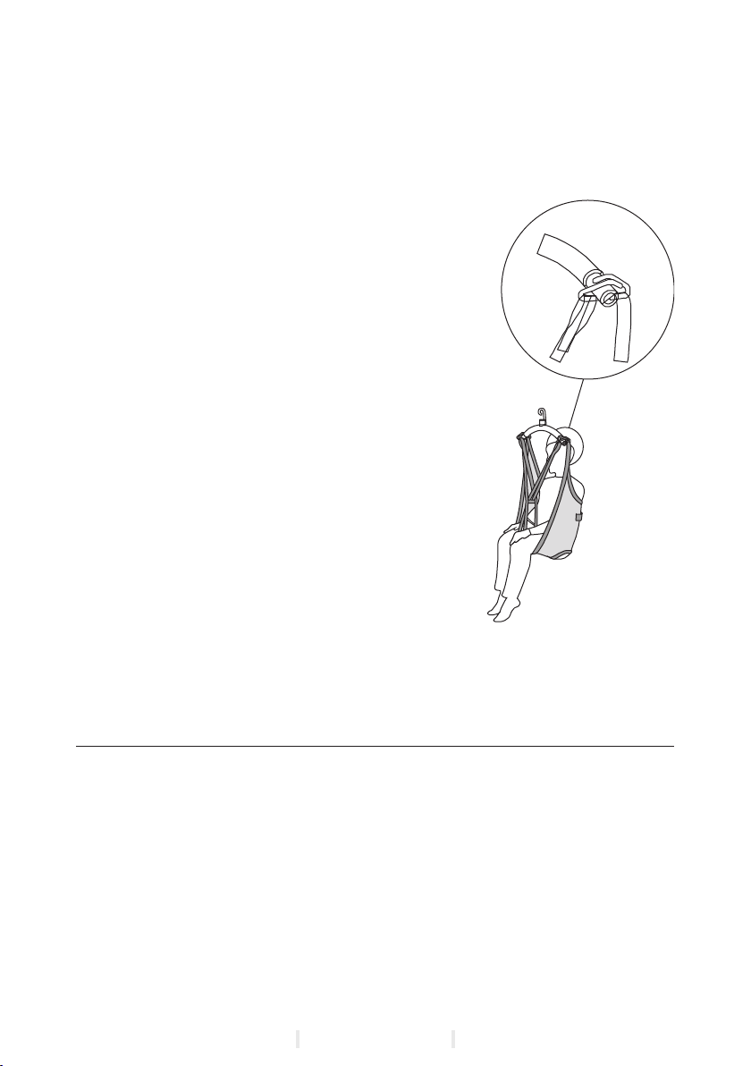
Description of the safety strap function
The lifting stops automatically, when not performed vertically, when the lifting
strap is twisted, or in case of overloading.
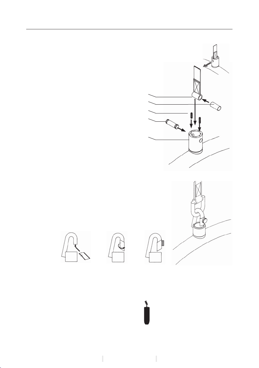
2.04 Recharging / connecting the hoist
Recharging
When the green lamp on the bottom of the DH 2000 starts ashing, the hoist
must be recharged as soon as possible. The DH 2000 is placed at the charging
station, which is mounted in an appropriate place in the rail system and con-
nected to the charger. When the hoist is run into position in the charging sta-
tion, the hoist will respond with a number of “beeps” depending on the charging
state of the battery. At the sound of 3-5 “beeps” the battery is fully charged.
At the sound of 6-30 “beeps” recharging is required and the hoist should be
recharged for a longer period. If the beeping sound does not stop, the batteries
are defective. After recharging, when the hoist is run out of the charging station,
there will be the sound of one “beep”. During recharging the hoist is secured
in the charging station by means of a spring retainer. Recharge the DH 2000
overnight or when not in use to encure a long lifespan of the batteries.
2.05 Connection of Charging station
Recharging in single-track rail - systems.
Bring the DH 2000 to the charging station.
The charging station signs with a number of beep’s, depending on the energy
level of the battery. The beep is a guarantee for charging.
Recharging in room-covering rail systems.
Bring the DH 2000 to the end of the traverse rail and the traverse rail to
the end of the parallel rails where the charging station of the room-covering
system is placed. The charging station signs with a number of beep’s, depen-
ding on the energy level of the battery. The beep is a guarantee for charging.
© Guldmann GB-896/08/08 • # 900662

11
2.06 Accessories
Transverse drive motor.
The transverse drive motor makes the hoist fully automatic. It is built into the
DH 2000 without changing the outer dimensions and the visual impression of
the hoist.
When the hoist is provided with the drive motor, the spped is gradually incre-
ased to 8 metres / minute to ensure a smooth up-start.
IR remote control.
The IR remote control is often used with the hoist with transverse drive motor,
enabling the user to “ call “ the hoist and thus to a certain degree be indepen-
dent of the carer.
Important:
When the user is independent, the IR remote control sender should be attac-
hed to the user, so that it will always be within the reach.
Lifting Slings
Please ask the distributor for a special leaet on Lifting Slings.
Extension strap
This is used if the distance between rail and oor exceeds 3 metres, and is
ordered separately. If E.G. the distance is 3.5 metres between rail and oor
you should order an extension strap of 0.5 metres length.
Switch track
The switch track is used when it is necessary to divide
a single track rail system into two tracks.
The manual switch track is activated by pulling one of
the strings hanging down from the switch track. The DH 2000 is driving in the
direction of the string pulled. The electric switch track is activated by pressing
the key on the hand control once.
Safety
Via mechanical safety devices the product secures the hoist
against running off the rail or getting jammed.
Turntable
The turntable is used in rail systems where it is
necessary to combine 3 or 4 directions.
The DH2000 is positioned in the centre of the tur-
ntable prior to use. The turntable is activated by
pressing the key of the hand control. When acti-
vating the key once, the turntable turns 90°. Keep
pressing the key till the desired direction is reached.
Safety
Via mechanical safety devices the product secures the hoist
against running off the rail or getting jammed.
© Guldmann GB-896/08/08 • # 900662

12
Combi-lock
The Combi-lock is used when joining a single-
track system with a room-covering system, or
when joining two room-covering systems.
By using the Combi-lock the two systems are
locked together, for instance when the hoist pas-
ses from the single-track system in the bedroom
on to the traverse rail in the room-covering system in the bathroom.
The Combi-lock is activated by pressing the key of the hand control once.
Safety
Via mechanical safety devices the product secures the hoist against running
off the rail or getting jammed.
3.00 Dismantling & Transport
3.01 Dismantling the hoist
The hoist can be dismantled, see section 1.8
3.02 How to transport the hoist ?
The hoist can be dismantled for transport and storage, see section 3.1
3.03 How to package the hoist for transport ?
Guldmann recommends that the dismantled hoist is always transported in its
original packaging.
4.00 Maintenance and storage
4.01 Cleaning the hoist
Hoist and lifting hanger can be cleaned using a damp sponge..
Do not use chemicals or autoclaving to cleanse the hoist.
The charger must only be wiped using a dry cloth.
The charging system is maintenance-free as it is placed inside the rail
system.
4.02 Storing the hoist
The hoist should be kept in a dry room, where the humidity does not exceed
70 per cent. This is why the hoist must never be kept in bathrooms and
similar areas.
© Guldmann GB-896/08/08 • # 900662

13
4.03 Long-term storage
The hoist should be stored in cool rooms e.g. a basement.
The hoist should be stored at temperatures below 15 °C due to the risk of
running the batteries down. The Guldmann Service Team recommends that
the fuses are removed from the hoist when it is stored for long periods of
time.
4.04 How to prevent / avoid corrosion ?
The hoist should not be kept / remain in damp surroundings for long periods.
Water vapour might liquefy into water on the hoist, thus causing corrosion /
rust in the bearings.
The hoist should not be exposed to sudden cold or warmth. This means that
one should not take a cold hoist into e.g a hot bathroom.
The DH 2000 shall be ordered with a treatment / coating if it mainly is used in
agressive enviroment, eg. swimming baths.
In swimming baths and bathrooms where strong gasses may be present, the
hoist is particularly exposed to corrosion.
4.05 Maintenance which should be carried out by the owner?
Check at regular intervals that the lifting strap has no damages. If the lifting
strap is damaged, DH 2000 should not be used. The lifting strap must only be
exchanged by an atuhorized installer.
5.00 Service and Life Span
5.01 Life span and servicing of hoist
According to the international standard EN/ISO 10535 “Hoist for the transfer
of disabled persons - Requirements and test methods” a safety inspection of
the hoist must be performed at least once a year.
Servicing and estimation of life span are based on the annual service check
and maintenance carried out by a service engineer or by the Guldmann Ser-
vice Team.
The hoist has an expected life span of 15 years. The hoist must then be
assessed by qualied service staff as to its future use.
Spare parts lists and drawings are available from manufacturer or supplier.
5.02 Battery and fuses
Change of batteries and fuses should be carried out by a service engineer or
by the Guldmann Service Team.
© Guldmann GB-896/08/08 • # 900662

14
5.03 Service check - Allround
During the inspection a service report shall be made, describing what has
been checked and exchanged.
Worn or defective parts shall be replaced by new spareparts from
V. Guldmann A/S.
1 Visual check of the product.
• Check the product for wear and tear
• Check the product for any deformity
• Check that the product does not show any other diciencies.
2 Test of the product, as during normal use.
• Check all functions on the product, with and without load,
• ( eg. Up, down, forward, backward, out and in ).
• Check the emergency lowering is operational.
• Check the emergency stop is operational.
• Check the charging indicator is operational.
3 Dismantle the cover / fence.
4 Check the electrical condition of the products
• Check the batteries and measure the:
• Input / Voltage
• Output / Voltage
• Check electrical functions and signals
• Check all wirings for errors and defects
• Check wire lead-ins
• Check all possible conections, plugs etc.
5 Check the mechanical condition oft the product
• Clean the product for dirt and other impurities
• Inspect and evaluate the vital parts of the product
• Exchange defective and worn
• Grease the product
6 Mount the cover / fence
7 Point 1.2 is carried out one more time as a control function
8 Have new errors or problems arisen in point 7?
• If new problems have arisen, go back to point 3
• If no problems have arisen, nish the inspection.
9 When a service inspection including service work or exchange of com-
ponents has taken place, the nal check should comprise a weight test
with the product’s nominal load.
If the DH 2000 has been silicone-coated for use in wet environment, this coa-
ting must be renewed if it shows sign of drying.
© Guldmann GB-896/08/08 • # 900662

15
5.04 Trouble Shooting
If the DH 2000 does not react when pressing the keys of the hand con-
trol ?
Check that the plug for the hand control is correctly inserted
If the green light on the bottom of the DH 2000 does not come on when
pressing the keys of the hand control ?
Check that the emergency stop is not activated
Check that the batteries are charged
Check that the charger is on
the hand control could be faulty or a fuse is blown in the hoist
Please contact your local Guldmann representative
If the green light on the bottom of the DH 2000 is still ashing after the
hoist has been recharged ?
Check that the light on the charger is on when recharging the DH 2000
Check that the charger is on
Check that the charging points of the DH 2000 have been connected properly
to the charging station
Please contact your local Guldmann representative
6.00 Technical Specications
Dimension (WxHxL): . . . . . . . . . . . . . . . . . . . . . . . . . . . . . . 350x190x245 mm
Maximumliftingcapacity:.................................... 175kg
No. of lifts per charging:. . . . . . . . . . . . . . . . . 100 with 85 kg & 40 with 175 kg
Lifting speed with 85 kg load: . . . . . . . . . . . . . . . . . . . . . . . .2000 mm pr. min.
Liftinginterval:..........................................2000mm
Min. distance from pivot joint on the lifting hanger to the ceiling: . . . . 400 mm
Max. distance from pivot joint on the lifting hanger to the ceiling:. . . 2400 mm
Total weight of hoist without sling:
withouthanger: ...........................................14,5kg
Liftinghanger: ............................................ 2,0kg
Electrical connection for charger / hoist: . . . . . . . . . . . . . . . . . . . . 230V / 115V
(depending on national voltage standards)
Connection between charger and hoist: . . . . . . . . . . . . . . . . . . . . . . . 24V DC.
Consumption / effect of actuator:. . . . . . . . . . . . . . . . . . . . . . . . . . . . . 240 VA.
Charger, fully automatic: . . . . . . . . . . . . . . . . . . . . . . . . . . . . 24V DC / 0,5 Ah.
Chargingtime:.......................................Max.8hours
Batteries, gasproof and free of maintenance: . . . . . . . . . . 2 pcs 12V / 4,0 Ah
Battery protection at too low a voltage: . . . . . . . . Yes, disconnects below 17V
Permittedperiodicload ......................................15/85
(working time / breaks in percentages)
Guarantee ................................................1year
•
•
•
•
•
•
•
•
•
•
© Guldmann GB-896/08/08 • # 900662

V. Guldmann A/S
Corporate Ofce:
Graham Bells Vej 21-23A
DK-8200 Århus N
Tlf. +45 8741 3100
Fax +45 8741 3131
www.guldmann.dk
© Guldmann GB-896/08/08 • # 900662
This manual suits for next models
2
Table of contents
Other Guldmann Chain Hoist manuals
Popular Chain Hoist manuals by other brands

Vital
Vital V-Lever VR2 user manual

BorMann
BorMann BPA5118 manual

Jet
Jet AL100 Series Operating instructions and parts manual

Jefferson Professional Tools & Equipment
Jefferson Professional Tools & Equipment JEFPOWH250 user manual

Columbus McKinnon
Columbus McKinnon 622 Series Operating, Maintenance & Parts Manual

Power Fist
Power Fist 8873176 manual