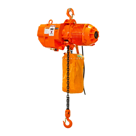
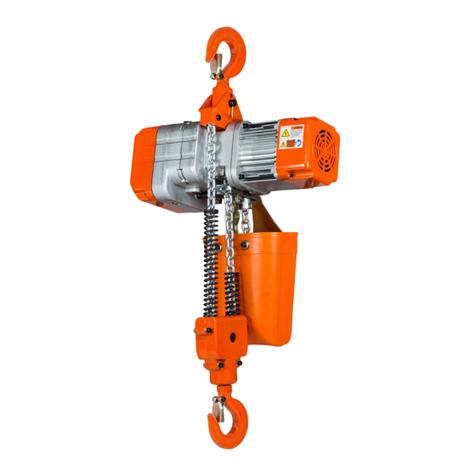
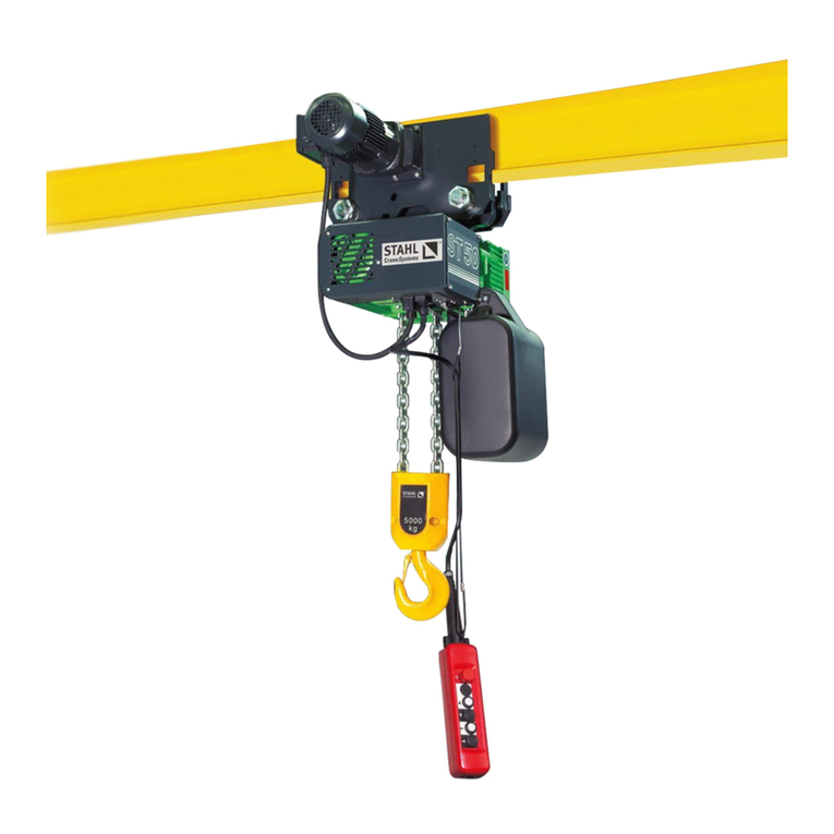
Prowinch PWH User manual

PWH
Powered Electric Chain Hoist
User’s Manual / Manual de usuario
Safety Warnings / Advertencias de Seguridad

32 PWH
PWH
Version 1.0 | 3 |
| 2 | Version 1.0
This page intentionally left blank
PROPERTY REGISTRY Nº 189487
ANY REPRODUCTION IS FORBIDDEN
PROPERTY OF PROWINCH® 2018 - V8.0 ALL RIGHTS RESERVED
PROWINCH LLC COMPANY WITH QUALITY MANAGEMENT SYSTEM
Prowinch® LLC declares that it has made available to the Customer each and every one of the security warnings related to the
purchased product and that, as a result, it does not assume any responsibility for any damages or losses that may be suered
by the client or third parties. Cause or as a direct or indirect consequence of the breach or omission of any of the instructions or
safety warnings contained in the User Manual and Security Warnings corresponding to the unit purchased.
In this sense, Prowinch® LLC will not be liable for accidents and / or damages to persons and / or property resulting from the
negligent use of the product. In no case does Prowinch® LLC assume any liability arising from the use of these voluntary rec-
ommendations, and does not oer any guarantee in relation to them. These recommendations do not take precedence over
the current safety regulations of the plant. For purposes of enforcing the Warranty of the product purchased, Prowinch® LLC,
will only be liable for any damage when it is possible to prove that the user has followed each and every one of the warnings
contained in the User Manual and Safety Warnings.
PROWINCH® DISCLAIMER
1. It is the sole responsibility of the Client / User to verify
that the acquired equipment, products and accessories
comply with the characteristics, capacities, requirements,
components, accessories and other conditions for the use
that the Client / user intends to give it.
2. It is also the sole responsibility of the Client / User to en-
sure that the equipment and products purchased are oper-
ated and maintained with adequate safety standards and by
personnel duly trained in the use thereof. The Client / User
is also responsible for implementing all the security mea-
sures necessary to prevent accidents or damages to people
or property and for following the indications and warnings
of the corresponding manual.
3. Any assistance provided by Prowinch® LLC in the selec-
tion of the equipment, the capacities and characteristics re-
quired by the clients is delivered free of charge and based
on the information about the application, use and require-
ments indicated by the Client itself. It does not correspond
to Prowinch® LLC to verify the accuracy of the given informa-
tion. It is the sole and exclusive responsibility of the Client
-or who will use the equipment and products acquired- to
ensure that the specications comply with the capabilities,
characteristics, up-to-date maintenance and everything
necessary for a correct and safe operation in relation to the
intended use.
4. Prowinch® LLC recommends the use of winches with 4
brakes for personnel lifting. The use of winches of 3 brakes
or less or safety features lower than the best available for
personnel lifting, is the sole responsibility of the customer
in order to guarantee the safety of the personnel and users
of the equipment it is necessary to carry out the inspections
and maintenance of the equipment according to the rec-
ommended frequency in relation to its work cycle. It is
mandatory to keep record and evidence the written and
photographic reports of: Maintenance, Start-up, Load
Tests, Training, Certications, Inspections and Reports of
failures and accidents.
5. The aforementioned reports must be sent by email to
after the occurrence of an event.
6. Compliance with the timely implementation of the
mandatory activities described in points 6 and 7 in ad-
dition to all the activities mentioned in the correspond-
ing rules applied are the sole responsibility of the user.
Failure to comply with the foregoing conditions releases
Prowinch® LLC from any type of Liability and Warranty to
the team, customer, sta or user, or any other liability that
could be attributed to Prowinch® LLC.
7. The information contained in this manual may con-
tain technical errors or inaccuracies. Prowinch® LLC is
not responsible for typing errors, omission or incorrect
information.
8. This manual is subject to change without prior notice.
Download the latest version available at www.prowinch.
com.
9. Always check www.prowinch.com for the latest infor-
mation regarding this product.

54 PWH
PWH
Version 1.0 | 5 |
| 4 | Version 1.0
PWHF1000iW PWHC1000iWPWHF1000uW PWHC1000uWPWHF1000i PWHC1000i
PWHF1000u PWHC1000u
PWHF500i PWHC500i
PWHF500u PWHC500u
PWHF500uW PWHC500uW
1 Ton Electric Chain Hoist
20 ft. FEC G80 Chain M3/
H2 220/240V Wireless
1 Ton Electric Chain Hoist
Power Trolley 20 ft. G80
Chain M3/H2 220V
1 Ton Electric Chain Hoist
20 ft. FEC G80 Chain M3/
H2 220/240V Wireless
1 Ton Electric Chain Hoist
Power Trolley 20 ft. G80
Chain M3/H2 110/120V
1 Ton Electric Chain
Hoist 20 ft G80 Chain
M3/H2 220/240V
1 Ton Electric Chain
Hoist Power Trolley
20 ft. G80 Chain M3/
H2 220/240V Wireless
1 Ton Electric Chain
Hoist 20 ft G80 Chain
M3/H2 220/240V
1 Ton Electric Chain
Hoist Power Trolley
20 ft. G80 Chain
M3/H2 110/120V
Wireless
1/2 Ton Electric
Chain Hoist 20 ft.
G80 Chain M3/H2
220/240V
1/2 Ton Electric
Chain Hoist Power
Trolley 20 ft. G80
Chain M3/H2 220V
1/2 Ton Electric
Chain Hoist 20ft.
G80 Chain M3/H2
110~120V
1/2 Ton Electric
Chain Hoist Pow-
er Trolley 20 ft.
G80 Chain M3/H2
110/120V
1/2 Ton Electric
Chain Hoist 20 ft.
G80 Chain Wireless
120V
1/2 Ton Electric
Chain Hoist Pow-
er Trolley 20 ft.
G80 Chain M3/H2
110/120V Wireless

7
6Safety Precautions
Safety Precautions
Version 1.0 | 7 |
| 6 | Version 1.0
Thank you for purchasing our Prowinch® Electric Chain Hoist.This User Manual provides im-
portant information for personnel involved with installation, operation, and maintenance
of this product. Read this User Manual before installing, operating, or maintaining product.
SAFETY PRECAUTIONS
Mandatory use of:
Hard Hat Safety Glasses Safety Gloves Safety Shoes
Prowinch® Electric Chain Hoist is designed for safe
and reliable service if operated according to User
Manual.
Respect all warnings for personnel and third party
safety. Inadequate operation may cause injuries or
damage equipment.
Read and understand this User Manual carefully
before installation and commission of equipment. Keep
this User Manual in an accessible place for consultation.
Hoists used improperly may harm users and result in
wounds, injuries or death. This User Manual highlights
symbols and notes for caution, warning and danger.
Attention to these areas ensures safety of operator.
Safety Precautions
This symbol indicates a dangerous sit-
uation which if not avoided may cause
minor or moderate wounds. It is also
used for indicating unsafe practices
This symbol indicates a potentially
dangerous situation which if not
avoided may cause severe injuries
or death
All operators and other users who are near the steel chain or its load must wear required
safety equipment: gloves, safety helmet / hard hat, safety shoes and eye protection.
Before installing, removing, inspecting, or performing any maintenance on the hoist,
the unit must be unplugged, locked out, and tagged out. Do not use this equipment in
hazardous locations.
Read and understand the contents of this User Manual thoroughly before handling the product. Practicing
correct and safe operating procedures and carrying out the recommended preventative maintenance will
ensure a long, reliable, and safe service.
After carefully reading and understanding the User Manual, store it for future reference.
WARNING: DANGER:
Hazardous Voltage
Inside.
Disconnect power
before opening.
PWDA005-V1.0
DANGER

9
8Safety Precautions
Safety Precautions
Version 1.0 | 9 |
| 8 | Version 1.0
Before using equipment:
During Operation:
ALWAYS
NEVER
• Read and understand instructions in this User Manual and labels associated with hoist before operating
equipment.
• Wear appropriate clothing: Do not wear jewelry or loose clothes as they might get attached to chain or
hook.
• Wear leather gloves.
• Wear non-slippery safety shoes, helmet, and eye protection.
• Perform full check of hoist. Check for damaged parts or unusual characteristics. Keep a safe distance:
suggested distance is at least 1.5 times length of hoist’s chain. Broken or loose chain may cause injuries or death.
• Check hoist and chain are properly lubricated.
• Secure electric chain hoist to a suitable support.
• Visually inspect all electric chain hoists in addition to regular and maintenance inspections
• Refer to maximum load capacity displayed on ID plate of hoist, not capacity of hook.
• Stop operation immediately if unauthorized personnel enter working area.
• Check state of hoist: If engine gets too hot, stop hoist and let it cool for a while.
• Stop, check, and secure load if hoist stops or loses movement during operation.
• Focus on operation. Pay attention at all times and keep proper balance.
• Unplug hoist after operation.
• Exceed maximum load capacity.
• Operate damaged or malfunctioning hoist.
• Operate hoist if behaving unusually.
• Lift, support, transport people, or lift or support loads over people.
• Walk over chain.
• Operate electric chain hoist with twisted, kinked, damaged or worn load chain.
• Use load chain as a sling around load.
• Operate a hoist if ID plate or safety labels are missing or illegible.
• Operate electric chain hoist when exposed to rain or water.
• Use if operator is sick or not completely attentive.
• Leave hoist unattended if energized or loaded.
• Operate hoist unless load is centered.
• Operate beyond limits of load chain or extend chain.
• Use load chain or hook as an electrical or welding ground.
• Remove labels on electric chain hoist.
• Use hoist to lift load at an angle, nor pull or drag load
Inspection, Maintenance and Repairs:
• Only trained and authorized personnel may make repairs to equipment.
• Use only original Prowinch® parts. The use of any other part immediately voids warranty.
• Failure to use only original Prowinch® parts may endanger operator.
ALWAYS
NEVER
• Check quality of electrical connections.
• Check chain and keep it lubricated.
• Prevent others from being beneath load.
• Regularly inspect and maintain hoist.
• Check correct installation of hoist before using.
• Avoid contact with explosive gases or materials.
• Overload.
• Transport people or animals.
• Stand below load.
• Use hoist if exposed to rain, snow, or electrical storm.
• Leave load suspended for extended period of time. This may cause component deformation an accident.
• Exceed designated operating temperatures stated in this User Manual (dier depending on model).
• Expose hoist to water, sand, corrosive environment or other substances which may damage equipment.

11
10 Safety Precautions
Safety Precautions
Version 1.0 | 11 |
| 10 | Version 1.0
1. Do not overload 2. Check the quality of the elec-
trical
3. Periodically check the chain
and keep it lubricated.
4. Do not transport people or
animals.
5. Do not place under load and
prevent others from doing so.
6. Do not use hoist if exposed to
rain, snow or lightning.
7. Regularly inspect and main-
tain your hoist.
8. Always check correct hoist
installation before use.
9. Do not leave the load
suspended for long periods of
time. It may cause deformation of
the component or cause an acci-
dent.
GENERAL ENVIRONMENTAL PRECAUTIONS
WARNINGS
Do not exceed the operating temperatures for
which the hoist is designed. This is stated in this
manual and may vary depending on the model.
When exposed to water, sand, corrosive envi-
ronment and / or Other potentially harmful
substances may damage the equipment.
Avoid contact with gases or
explosive materials.

13
12 Safety Precautions
Safety Precautions
Version 1.0 | 13 |
| 12 | Version 1.0
Hanging Pendant Control Hanging Pendant Control
Do not install the pendant control cable without the strain relief cable (steel cord).
Make sure to connect both cables.
DANGER:
XX
1
1
1

14
Specications Specications
15
Version 1.0 | 15 |
| 14 | Version 1.0
1. Electric Trolley
7. Safe Brake System
8.Heavy Dutty Stator
9.Load Chain
10. Hooks
6. Reverse Phase Protector
2.Upper and lower
limit switch
3. Chain Wheel
4. Chain Bag
5. Control System
The range of ange width is adjustable.
Motor include disc type brakes. Side
guide are to promote the trolley motion
smooth and minimize the wear of wheel
and beam.
It’s the special electrical installation of con-
trolling the circuit not work in case of wirring
error in the power supply.
The limit switch will cut o the motor cir-
cuit and prevent the damage to hois struc-
ture and load chain when over-lifting or
over-lowering happens.
Electric brake is designed for easy access
and simple adjustment. It allows instant
brake as soon as the electric power is cut
o. Thus the braking safety while loading is
guaranted.
Light aluminum alloy shell, light but hard.
The cooling n is specially designed to en-
sure quick heat dissipation with the rate up
to 40% and continuous service.
Increasing the number of load sheave pock-
ets helps relieve vibrations produced by
revolving polygonal sheave on the hoist’s
body and load chain.
Canvas chain containers is a standard t-
tings. Operation fabricated steel containers
are available for long lift applications.
Canvas chain containers is a standard t-
tings. Operation fabricated steel contain-
ers are available for long lift applications.
The length of the control is 4 feet less
than the lifting height, which allows it to
be easily operated from ground-level. An
optional wireless remote control is avail-
able for extra convenience.
Load hook is forged carbon steel hook with
a heavy-duty hook latch. Thrust bearing in
hook allows 360
1
7
6
3
8
2
4
9
10
5

16
Specications Specications
17
Version 1.0 | 17 |
| 16 | Version 1.0
MAIN SPECIFICATIONS
Observations
Load Level And Service Life
Specication Chart (For all models of Prowinch® Electric chain hoists).
ITEM # SPECS
Operating temperature range (ºC) -20 to + 40
Operating humidity range (%) 85 Or Below
Protection class Hoist IP55
Button Switch IP55
Power 3 phases, 200 - 600V, 50/60Hz
Noise level (dB) Single speed hoist 81
Chain specs Double speed hoist 81
Chain specs
Working load limit Diameter (mm) Chain pitch (mm)
0,3T, 0,5T 6,3 10
1T, 2T, 3T 7,1 21
1,5T, 2T 10 30
2,5T, 3T, 5T, 7,5T, 10T, 15T, 25T 11,2 34
Do not use Prowinch® Electric Chain Hoists when temperature and humidity exceed range of
Specication Chart.
Our hoists are designed to lift up and down under common atmospheric and working conditions.
Guarantee of service life and safety for Prowinch® Electric Chain Hoists depends on proper installation, mainte-
nance, and operation.
Our electric chain hoists are designed to meet 1Bm, 1Am and 2M Load Level in FEM standards FEM 9.51, depending
on the model.
The working class of your chain hoist is rated on ID plate of equipment.
ADVANTAGES
1. All aluminum die-cast body, make hoist much lighter weight.
2. Cooling fan for motor, make hoist service much longer life.
3. Motor overheating protector
4. Brake system: Electronic magnetic brake
5. Safety clutch for overload protection
6. Unique guide structure
7. Limit switch for upper and lower: 20° lifting angle allowance
8. Self-lock contactor
9. Safety clutch
1
8
9
6
5
7
2
4
3

18
Specications Specications
19
Version 1.0 | 19 |
| 18 | Version 1.0
Selection of engines for lifting equipment
Group Intermittent Service Short-Term Service
F.E.M. ISO Cycles/h Starts/h (ED%) Operation period min
1 DM M1 15 90 15 7.5
1CM M2 20 120 20 7.5
1 BM M3 25 250 25 15
1:00 AM M4 30 180 30 15
2 MW M5 40 240 40 30
3M M6 50 300 50 30
4M M7 60 360 60 60
5M M8 60 360 60 >60
Capacity
(ton) A B D R T
Speed
(50HZ)
m/min
Motor
(Kw)
Min. Radius
of turn
Beam
Range
0.5 248 196 25 146 159 12.2 0.12 0.8 100
Capacity
(ton) A B D R T
Speed
(50HZ)
m/min
Motor
(Kw)
Min. Radius
of turn
Beam
Range
1 315 212 31 142 231 nov-21 0.4 0.8 52 - 145
2 325 220 36 142 231 nov-21 0.4 0.9 82 - 185
3 340 250 43 142 231 nov-21 0.75 1.0 100 - 185
5 400 291 54 142 231 nov-21 0.75 1.5 100 - 220
7.5 400 291 54 142 231 nov-21 0.75 1.8 100 - 225
10 500 370 70 142 231 nov-21 0.75 2.0 150 - 255
LOAD LEVEL DEFINITION CUBIC VALUE AVERAGE DAILY OPERATION HOURS
1 (light)
Mechanism and parts
are frequently under
light load, and there is
under light load, and
there is no max. load
unless exceptional con-
ditions.
K ≤ 0.50 ≤ 2 2 ~ 4 4 ~ 8 8 ~ 16 ≤ 16 > 16
2 (medium)
Mechanism and parts
are frequently
under light load,
but also under
max. load with
low frequency
0.50 < K ≤ 0.63 ≤ 1 1 ~ 2 2 ~4 4 ~ 8 8 ~ 16 ≤ 16
3 (heavy)
Mechanism and parts
are frequently under
medium and heavy
load.
0.63 < K ≤ 0.80 ≤ 0.5 0.5 ~ 1 1 ~2 2 ~ 4 4 ~ 8 8 ~ 16
4 (overweight)
Mechanism and parts
are frequently under
max. or almost reach
max. load.
0.80 < K ≤ 1 ≤ 0.25 0.25 ~ 0.5 0.5 ~1 1 ~ 2 2 ~ 4 4 ~ 8
1 BM 1:00 AM 2M 3M 4M 5M
% Operation hours
Load level 1
% Operation hours
Load level 2
% Operation hours
Load level 3
% Operation hours
Load level 4

20
Specications Specications
21
Version 1.0 | 21 |
| 20 | Version 1.0
• Apply lubricant to areas of load chain (shaded areas in gure below) that contact load sheave.
• Hooks and Suspension Components
• Hooks and bearings should be cleaned and lubricated at least once per year for normal usage.
• Clean and lubricate more frequently
• for heavier usage or severe conditions.
• Suspension pins should be lubricated at least twice per year for normal usage; more frequently
for heavier usage or severe conditions.
For dusty environments, it is acceptable to substitute a dry lubricant.
INSPECTIONS & MAINTENANCE
Periodic Inspection
Daily Inspection Of Electric Chain Hoists
Oil & Lubricant Recommendations
Capacity
(ton) A B D E R T
Speed
(50HZ)
m/min
Motor
(Kw)
Min. Radius
of turn
Beam
Range
1 325 230 31 32 142 231 nov-21 0.4 0.8 52 - 145
2 375 245 31 44 142 231 nov-21 0.4 0.9 82 - 185
3 400 250 36 44 142 231 nov-21 0.75 1.0 100 - 185
5 420 290 43 44 142 231 nov-21 0.75 1.5 100 - 220
Load Chain
Do not allow chain to run dry.
Lubricant greatly increases life of load chain. Weekly lubrication and cleaning is satisfactory, but under hot, dirty, and ex-
treme conditions it may be necessary to clean chain at least once a day and lubricate it several times between cleaning.
Apply sucient lubricant to obtain natural runo and full coverage, especially in interlink area.
Apply Lubriplate® Bar and Chain Oil 10-R or equal lubricant. Machine or gear oil (grade ISO VG 46 or 68 oil or equivalent)
may be used as an alternative lubricant but must be applied more frequently.

22
Specications Specications
23
Version 1.0 | 23 |
| 22 | Version 1.0
Attrition of chain
di-am-eters
Check by chain
measurement tool
Deformation,
damage, wind
Conrm chain is
not stuck to welding
spatters by visual
inspec-tion
• No deep cut
• No deformation
• No welding spatters
• No wind
• No chap
Replace load chains
Rust and
corrosion Visual check No remarkable rust
and corrosion Replace load chains
Distortion Visual check Correct distortion
Oil supply Visual check Oiling
No distortion due to bot-
tom block rollover of dou-
ble chain models
Adequate
supply of oil
ITEMS INSPECTION
METHODS STANDARDS Resolutions
to Deviations
Marks such as name-
plates,
labels etc.
Visual check
Proceed with cleaning,
repairing and replacing.
Record serial number
for
replacing
Deformation or
dam-age of
body parts
No remarkable deforma-tion, damage, de-
fect and chap
Replace parts which are
deformed, damaged,
and defective
Bolts, nuts, and cutters
loose or falling o Visual and tool check
• Correct installation
• A loose bolt will cause equipment
failure
• Ensure proper installation to avoid
death or serious injury
Precise installation
Extent of pitch Check by chain mea-
surement tool
No peeling and
clear marks

24
Specications Specications
25
Version 1.0 | 25 |
| 24 | Version 1.0
Limit switch Check by
pushing button
Operate until upper and
lower limit cause
automatic motor
shutdown
Replace limit switch,
disassemble and
clean limit lever
Movement
conrmation
Check by
pushing button
• Load chain can roll up easily
• Motor shutdown immediately when
operation stops
• All movements shutdown when E-stop
button pushed
• Other buttons cannot cause movement
when pushing the E-stop button
• All movements return to normal opera-
tion when E-STOP button relieved
Brake Check by
pushing button
Brake quickly activates and operation of
bottom hook immediately stops (amount of
movement of the load chain is within 2 to 3
rings)
Chain spring
Visual inspection
and measure
dimensions
Replace chain spring
CHAIN Length Of Spring
Standard
Ø6.3 145 140
Ø7.1 145 140
Ø10.0 135 129
Ø11.2 160 152
Attrition and opening
of the hook
Deformation, damage
and corrosion Visual check No remarkable deformation, harmful dam-
age and corrosion Replace hook
Hook safety block
Visual inspection,
fold and unfold
actions
-Can exactly fold inside the hook
-No deformation Dangerous
-Do not use hook if safety block is loosening
Improper use will lead to death or serious
injury
Hook movements
(rotate)
Visual inspection and
manual rotation
• No remarkable space between bottom
supporting and top
• equal at right and left
• easy to rotate 360°
Replace hook
Replace hook safety
block
Check by visual and
vernier caliper
No remarkable opening or attrition
LOAD A B C D E G
0.3 -0.5 27 18 25 17 35 28
1 34 24 30 24 42 32
2 46 29 39 30 49 40
3 56 35 49 34 59 48
5 67 43 67 44 60 48
7.5 -10 82 55 80 48 85 80
15 110 78 120 80 120 90
20-25 142 95 155 98 150 115

26 Installation
Installation 27
Version 1.0 | 27 |
| 26 | Version 1.0
Installation Process:
•Electric chain hoists must be grounded properly.
•Lock-out and tag-out the main disconnect switch in ed-energized position before performing any service on hoist.
•Customer must provide power supply cable, fuses, and main disconnect switch.
•Check supply voltage is same as nameplate voltage on hoist.
•Check voltage does not vary by more than ±10% from nominal value.
•Do not use conductors smaller than those listed in this User Manual to supply power to hoist.
•Never bypass limit switches, remove limit switch stops, or alter limit switch devices.
•Check the electric installation and wire gauge selection at www.prowinch.com and follow thesesimple steps)
LOCATE THE�
QR CODE
SCAN IT WAIT FOR
THE PAGE TO
LOAD
USE
INFORMATION
SCAN FOR
MORE INFO
LOADING...
Check and document hoist characteristics:
•Model number
•Rated capacity (tonnage)
•Lifting length of load chain (meter)
•Power supply
•Push button pendant assembly (2 button, 4 button or 6 button)
•Specially ordered optional items
•Beam width for trolley installation
Chain Bag Assembly
Switch on power supply to hoist and have professional operate push
button.
19

28 Installation
Installation 29
Version 1.0 | 29 |
| 28 | Version 1.0
Unpacking
Hoist should be carefully inspected upon delivery for damage which may have occurred during shipment or
handling. Check hoist frame for: dents or cracks, external cords for damaged or cut insulation, control station
for cut or damaged enclosure, and load chain for nicks and gouges.
1 Chain Bag (Box 1Pcs
2 Control Wire Rope 1m
3 Buon Switch 1 Pcs
Trolley Installation (models with trolley)
Adjust Trolley Width (models with trolley)
1. Insert suspension pins into lateral plate G and lock it with suspension pin bolts and nuts.
2. Install suspension pin with adjusting disk.
3. Install suspension pin into hanger T. The nameplates of hoist and trolley should be in the same direction.
4. Install additional gaskets into suspension pin before inserting it into lateral plate S.
5. Install outside adjusting disk and spacer pin into suspension pin. Insert cotter pin into spacer pin.
6. Cotter pin should be seen at the left side from front of trolley switch box.
• Adjust width of trolley according to drawing
(below) for appropriate clearance.
• Size A is the dimension of two side plates
that stretch outside completely.
• Size A must be approximate B (the width of
rail ange) + 4mm.
• Adjust size A by increasing or decreasing
adjusting disk. Insert cotter pin into spacer pin
and bend two branches of cotter pin until size
A is correct.
Nut must be tight, insert cotter pin and
bend it completely.
OPERATION
Qualied Operator
Safe and ecient operation of hoist requires an operator who displays caution and good judgment. The operator
must be fully alert, focused, and aware of surroundings.
Job must be strictly carried out under the good practices dened by international and national safety standards, such
as ANSI, OSHAS and ASME.
Operator training must be provided to ensure proper operation of equipment in compliance with instructions provid-
ed by equipment manufacturer and the provisions of ASME B30.
• Cannot read, understand and speak language of security labels, ID Plate and User Manual of equipment.
• Does not meet legal age requirements.
• Has visual or hearing impediments.
• Experiences mental, heart, or other illnesses that could interfere with safe operation of equipment.
• Has not been trained for use of hoist.
• Has not received User Manual for exact equipment.
• Has not demonstrated qualications through a practical operation of hoist.
This hoist must not be operated by someone who:
Install Trolley Into Beam (models with trolley)
1. Install trolley at end side of beam and slip trolley which has already been connected with hoist to
the appropriate place. This is the preferred method.
2. If rst method is unavailable:
• Unload brake stopper from hole A on suspension pin,
and insert it into hole Insert cotter pin again and bend it
completely.
• Pull side plate S and G outside, then lift trolley until
orbit wheel and orbit surface are in same horizontal posi-
tion. Put orbit wheel of side plate G onto surface of orbit.
• Hold side plate G and stop it from dropping from
orbit. Firmly push side plate S and put its orbit wheel onto
surface of beam.
• Unload brake stopper from hole B and insert into hole
A. Do not forget to bend cotter pin.

30 Installation
Installation 31
Version 1.0 | 31 |
| 30 | Version 1.0
Handling Precautions
ALWAYS:
NEVER:
• Keep hoist in good condition and make sure chain is lubricated and free to operate.
• Make sure electrical connection is grounded.
• Make smooth movements; avoid sudden changes of directions.
• Check functions of hoist and trolley without any load before operation.
• De-energize equipment after using it to avoid unintentional operation.
• Keep everyone a distance of at least 1.5 times the length of chain. If load falls it can cause serious injuries and
death.
• Make sure no one is beneath load.
• Use pulleys or other accessories that are not specically approved for relevant hoist model.
• Hoist load with tip of hook.
• Hoist load which is not vertical to hook.
• Use hoist to pull or drag load.
• Exceed maximum capacity of hoist.
Recommended Operation
1. Press button lowering unloaded hook down until limit spring touches limit switch. Be sure hoist stops auto-
matically before totally compressing spring.
2. Press button hoisting unloaded hook up until limit spring touches limit switch. Be sure hoist stops auto-
matically before totally compressing spring.
3. Test correct function of emergency stop button. When pressing button , press emergency stop button.
Ensure hoist stops immediately after pressing emergency stop switch. Hoist should not start again if any other
movement button is activated.
4. Rotate emergency stop switch clockwise to original position. When it bounces back, hoist can be started again.
If any of the above tests fail, unit must remain out of service, lockout/tagout power and request maintenance autho-
rized personnel to check circuit layout for automatic locking emergency stop switch.
5. Check lubricating condition of load chain (load chain has been lubricated before delivery, but could be dried in
transportation). Apply lubricant into chain bag to protect load chain.
6. 6. Check direction of chain eyes. All welding points should be same direction. Hoist cannot be operated prop-
erly unless all welding chain eyes are in same line.
• Position hoist in vertical position to load. Before moving trolley, make sure path of hook is free from any
obstacle.
• Lower hook near master link to hoist load and make nal adjustments to secure a 90º vertical lift operation
without any lateral deviation. Improper life angle may cause swinging of load.
• Attach hook to load link and make sure there are no people in working area. Check that no loose items can
fall from load.
• Begin by hoisting load two inches and stop. Check brakes are fully operational and load doesn’t lower while
stopped. Also check load is balanced and secured. Load may have changed shape or center of gravity when
suspended.
• To reach a desired position, movements must be smooth and continuous. Repeatedly pressing buttons may
heat up motor and damage equipment.
• Avoid sudden directions changes. These movements may damage equipment, prematurely wear down
brakes and cause accidents.
7. Avoid any obstacle when hoisting or traveling load.
8. Start movement of trolley and check there is no swinging of load and no obstacles in path. Stop movement
and make necessary adjustments if one of these conditions is present.
9. Once desired position is reached, slowly stop trolley. Position load completely vertical to desired spot
where load will be lowered.
10. Gradually lower load until it is secured on resting surface. Avoid hitting surface at high speed. If necessary,
stop movement before reaching surface and gradually lower to land load.
If hoist model has double dual/speed capabilities, always start with slower speed to avoid sud-
den accelerations. Decelerate before completing a stop.
WARNING:
NEVER leave load suspended without attention of the hoist operator!
DANGER:
ELECTRICAL AND VOLTAGE SELECTION
Available voltages 3 phase 220V 60HZ , 380V 50HZ and 440V 60HZ
Before switching voltage!

32 Installation
Installation 33
Version 1.0 | 33 |
| 32 | Version 1.0
Troubleshooting
DANGER
MAINTENANCE AND REPAIR
TO BE PERFORMED BY
AUTHORIZED
PERSONNEL ONLY
PWDA002-V1.0 ®
After unpacking, please careful check over the appearance of the cable, gear box and motor shell. Check the
quantity of the bellowing items as well. Every set of our hoist should including the bellowing standard spare
parts:
1. 2 directions wiring diagram for single speed
2. 4 directions wiring diagram for single speed
3. 6 directions wiring diagram for single speed
4. 2 directions wiring diagram for double speeds
5. 4 directions wiring diagram for double speeds
6. 6 directions wiring diagram for double speeds
7. Wiring diagram for single phase motor
The above mentioned wiring diagrams above are only for reference, user should take the one inside the electric
box as the proper one.
The electric specications can be made according to the follows:
�
/
/
/
/
/
/
. . .
...
Pm=OOMs =L=PUMs Pm=OOMs =L=QQMs Pm=OPMs =L=QSMs
• 3 Phase
• Frequency
• Single or double voltage

34 Installation
Installation 35
Version 1.0 | 35 |
| 34 | Version 1.0
PWH Single Phase Series Electric Chain Hoist Wiring Diagram
PWH Three Phase Series Electric Chain Hoist Wiring Diagram
LIMITED WARRANTY COVERAGE
PROWINCH products are warranted to the original purchaser for a period of three (3) years after the date
of purchase only to be free from defects in material and workmanship when subjected to normal, proper
and intended use. Within this period, PROWINCH will only repair or replace free of charge any part on a
product, after examination, is determined by PROWINCH to be defective in material or workmanship and
was not caused or substantially contributed to by other factors or circumstances beyond PROWINCH
control, including (but not limited to) defective installation, maintenance or repair, product modication
or alteration, any neglect misuse or excessive use, mishandling, product exposure to extreme or unsuit-
able conditions, normal wear and tear or failure to follow manufacturer’s instructions.This warranty does
not apply to damage that PROWINCH determines to be from repairs made or attempted by anyone other
than PROWINCH authorized personnel.
Return of the product with a copy of proof of purchase to PROWINCH, freight prepaid and insured, are
required for this warranty to be eective. If more than one year has elapsed from purchase date, proof of
periodic and regular maintenance by an authorized service must also be provided for this warranty to be
eective. PROWINCH does not cover freight or labor charges associated with the inspection and testing
of products which are found by PROWINCH not to be a valid warranty claim.
In no event shall PROWINCH be liable for any labor, removal and installation expenses, loss of time, man-
ufacturing costs, transportation, materials, loss of prots, incidental, special, consequential or punitive
damages, or for any costs, attorney fees, expenses, losses or delays, direct or indirect, alleged to be as
a consequence of any damage to, failure of, or defect in any product including, but not limited to, any
claims for loss of prots. PROWINCH disclaims any implied warranties, including without limitation,
any implied warranty of merchantability or tness for a particular use or purpose.
Acceptance of the exclusive repair and replacement remedies described herein is a condition of the
contract for the purchase of every PROWINCH product. If you do not agree to this condition, you should
not purchase the product.
PROWINCH® WARRANTY
DISCLAIMER

36 TroubleshoootingTroubleshoooting 37
Version 1.0 | 37 |
| 36 | Version 1.0
Faults, Cause, and Correction
Faults Major Cause Check Items Remarks
Does not
operate
in non-load
state
Brake
inaudible
Contactor is inau-
dible
Excessive voltage Power
Operating circuit break-o,
electric parts overheating
Power supply
Internal wiring
Contactor
Transformer
Up/Down limit switch
Button switch
Contactor is
audible
Power circuit break-o,
overheating motor, brake
Motor
Brake
Internal wiring
Contactor (junction fusing)
Brake audible Drive overheating, broken bearing Gear
Bearing
Operates in
non-load state
Unable to lift (motor roar) Default phase (single phase opera-
tion)
Power
Feed power
Motor
Contactor(junction fusing)
Slow lifting Low voltage Feed power
Unintended
reaction from
button
Inverse reaction from button
Anti-phase wiring Feed power
Incorrect wiring Internal wiring
Button switch
No reaction after pressing button
Circuit wire break Internal wiring
Button switch
Electric installation parts
Contactor
Up/Down limit switch
Contactor
Brake
Feed power
Internal wiring
Load chain
Load pulley, bare pulley
Gear
Bearing
Noise of brake Running (grating) Drag Brake
Stop Wear of friction plate Brake
Abnormal noise of rail curve
(grating) Obstruction of orbit/wheel Operation of trolley
Faults, Cause, and Correction
Faults Major Cause Check Items Remarks
Does not move
horizontally
Rail declining Trolley movement
Electric trolley /manual trolley Inclined pull (wheel is lifting) Trolley movement
Electric trolley /manual trolley Gear occlusion problem Trolley movement
Electric trolley /manual trolley Brake fastening Trolley movement
Electric trolley Electric faults Trolley movement
Irregular
movement and
noise
Electric trolley /
manual trolley
Rail & wheel interference
Trolley movement
Side wheel lacks oil
Uneven wheel wear
Wheel deformation
Rail deformation, wear
Bearing wear
Brake wear
Hook Deformation Hook
Load chain Wear, extension, deformation Load chain
Load chain Equipment not properly grounded Proper electric connection
Does not operate
in nonload
state
Brake inaudible
Supply Power Supply power voltage
Operating circuit break-o, electric
parts overheating
Cables
Internal wiring
Transformer
Electrical relay
Limit switch
Push Button Switch
Braking interval too large or small. Motor
Calibrate brake
Tripping as motor overheats Thermal Protector
Brake audible Bearing burning out, driving
component wear
Replace brake bearing
Bearing
Slow load operation Voltage drop Feed cable
Low and high speed status not
operating or working slow
Low voltage Supply power
Voltage drop Feed cable
Movement does not
correspond with
switch button
Movement did not correspond
with switch button
Motor wires connected Motor
Connection error Internal wiring
Switch button did not work Operating circuit break-o Push button switch
Electrical installation error Internal wiring

38 TroubleshoootingTroubleshoooting 39
Version 1.0 | 39 |
| 38 | Version 1.0
Faults Major Cause Check Items Remarks
Does not move
horizontally
Rail declining Trolley movement
Electric trolley /manual trolley Inclined pull (wheel is lifting) Trolley movement
Electric trolley /manual trolley Gear occlusion problem Trolley movement
Electric trolley /manual trolley Brake fastening Trolley movement
Electric trolley Electric faults Trolley movement
Irregular move-
ment and noise Electric trolley /manual trolley
Rail & wheel interference
Trolley movement
Side wheel lacks oil
Uneven wheel wear
Wheel deformation
Rail deformation, wear
Bearing wear
Brake wear
Hook Deformation Hook
Load chain Wear, extension, deformation Load chain
Does not operate
in nonload
state
Brake inaudible
Supply power Supply power voltage
Operating circuit break-o,
electric parts overheating
Cables
Internal wiring
Transformer
Electrical relay
Push button switch
Braking interval too large or small. Motor
Calibrate brake
Tripping as motor overheats Thermal protector
Brake audible Bearing burning out, driving com-
ponent wear
Replace brake bearing
Bearing
Slow load operation Voltage drop Feed cable
Low and high speed status not
operating or working slow
Low voltage Supply power
Voltage drop Feed cable
Movement does
not
correspond with
switch
button
Movement did not correspond
with switch button
Motor wires connected Motor
Connection error Internal wiring
Push button switch
Switch button did not work Operating circuit break-o Internal wiring
Push button switch
Electrical installation error Limit switch
Faults, Cause, and Correction
Condition Reason Action Cause Correction
No operation Abnormal supply voltage Power supply Improper power supply Check power supply regularly
Condition Reason Action Cause Correction
No operation
Wire break Repair or change
cable if broken
Strong force exerted Firmly x on cable support or
other equipment
2 or more Use anti-vibration cable in
movable part.
Twisted, knotted Straighten twists and knots
Interference with other
equipment
Use xed cable and avoid
outside interference
Overheating Check cables, exchange
if overheating
Temperature rise due to
o-capacity Adopt the proper cable
Binding cable used Do not use binding cable
Starting slow or no oper-
ation O-capacity
Check cable diameter,
replace cable if diameter is
too small
Voltage drop Adopt proper cable
Operation only in
free load (single phase)
1 wire break or
overheating Refer to above break or overheating item
Movement did not
correspond with switch
button (opposite)
Power line connection error Replace wires Wiring assembly error Connect wire as per wiring
diagram
Issues & Measures
Power supply
Power Cable
This manual suits for next models
14
Table of contents
Other Prowinch Chain Hoist manuals
Popular Chain Hoist manuals by other brands

ACCO Brands
ACCO Brands Accolift instructions

SVERO
SVERO 15B User instructions

Ingersoll-Rand
Ingersoll-Rand SMB010 Parts, operation and maintenance manual

unicraft
unicraft ESW 900 operating instructions

R&M
R&M LOADMATE LM05 II Series Installation and maintenance manual

Gude
Gude 55104 operating instructions

Ingersoll-Rand
Ingersoll-Rand KM Series Product information

HAUL MASTER
HAUL MASTER 631 Owner's manual & safety instructions

CMCO
CMCO Yale VSIII 0,25/1 operating instructions

KITO
KITO CX005 Owners/operators manual and safety instructions

Comeup
Comeup BMC-1000 quick start guide

Jet
Jet JLP-A Series Operating instructions and parts manual