• Never use the machine improperly or work in an unsafe manner.
• Always wear safety goggles, dust mask, and ear protection while operating
the saw (to comply with ANSI-Z87.1).
• Always remain alert when the saw is in use. Failure to pay attention on the
operator’s part may lead to serious injury.
• Before you start working, familiarize yourself with the work site and its
surroundings. Take notice of circumstances which may impede working or
traffic, observe soil conditions (good bearing or not), and take measures to
ensure safety (i.e. the shielding of roadworks from public traffic).
• Take measures to ensure that the machine is in a safe and trouble-free
condition prior to usage. Use the machine only when all protective devices
(i.e. guards, noise absorbers, emergency-off devices) are operating in the
intended locations.
• A visual check of the machine must be made at least once a shift to ensure
that visible damages or faults are recognized. Any changes (including
changes in the performance or behavior of the machine) must be reported
to the supervisor. If necessary, stop the machine at once and secure it.
• In the case of a malfunction stop the machine immediately and secure it.
Fix the problem as soon as possible.
• For starting and stopping the machine follow the operating instruction steps
and observe any indicator lights.
• Before switching the machine on make sure that the activated machine will
be of no danger to anyone.
• Be sure to connect the plug to a properly grounded receptacle to reduce the
risk of electric shock.
Some dust created by power sanding, sawing, grinding, drilling, and other
construction activities contains chemicals known to cause cancer, birth
defects or other reproductive harm. Some examples of these chemicals are:
.Lead from lead based paints,
.Crystalline silica from bricks and cement and other masonry products,
.Arsenic and chromium from chemically-treated lumber.
Your risk from these exposures varies, depending on how often you do this
type of work. To reduce your exposure to these chemicals: work in a well
ventilated are, and work with approved safety equipment, such as those dust
masks that are specially designed to filter out microscopic particles.
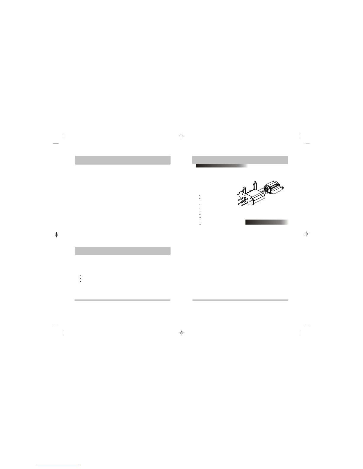
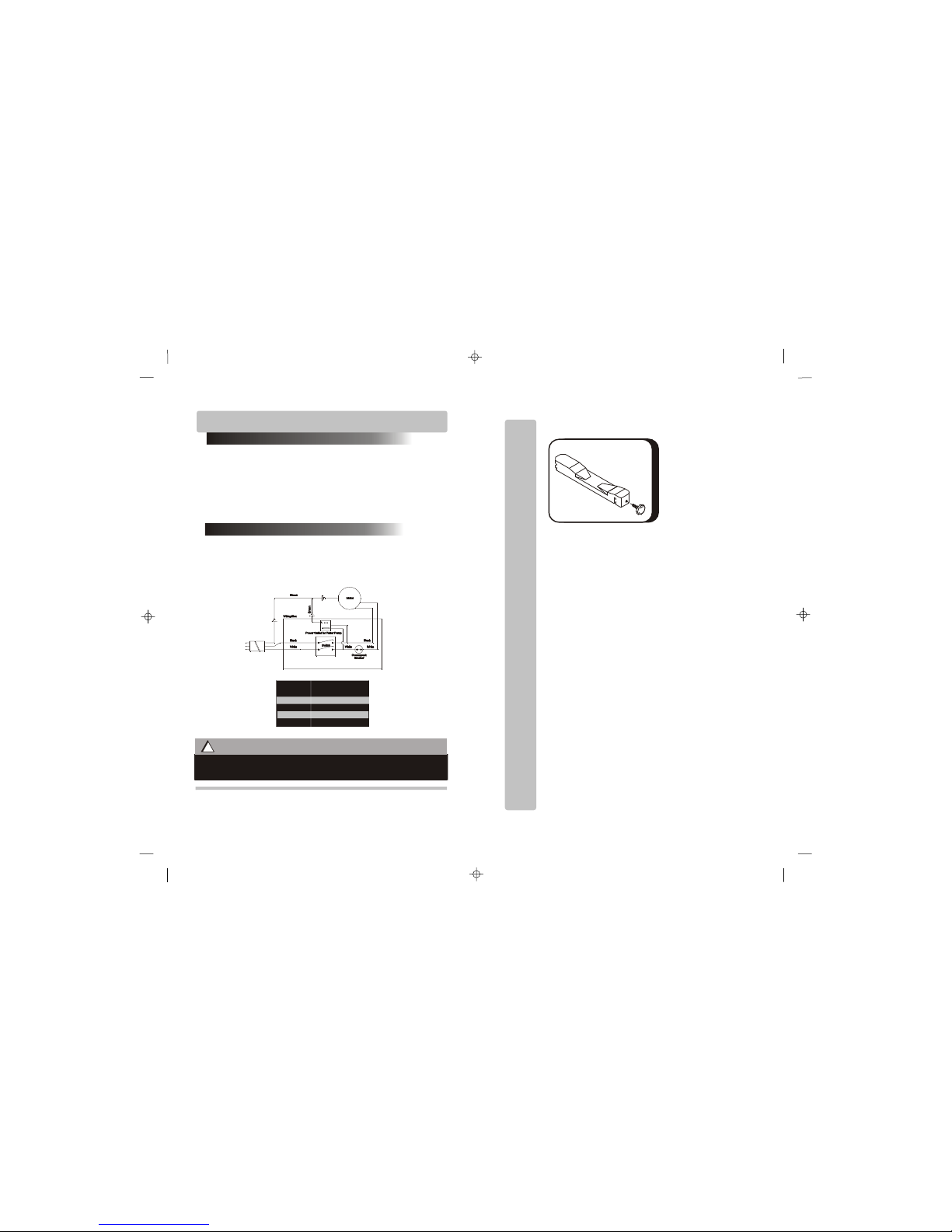
Open the container, carefully lift
the saw frame handles and
place it on a flat, level working
area. Be certain that you have
the following items before you
discard the container:
Saw
Slide-In Legs with Wheels
(1037 model only)
10” Saw Blade
Multiple Rip Guide
Multiple Wrench
Water Pump
Water Level Tube
Owner’s Manual
Drain Plug
Proceed to the following section
to complete assembly of the
saw.
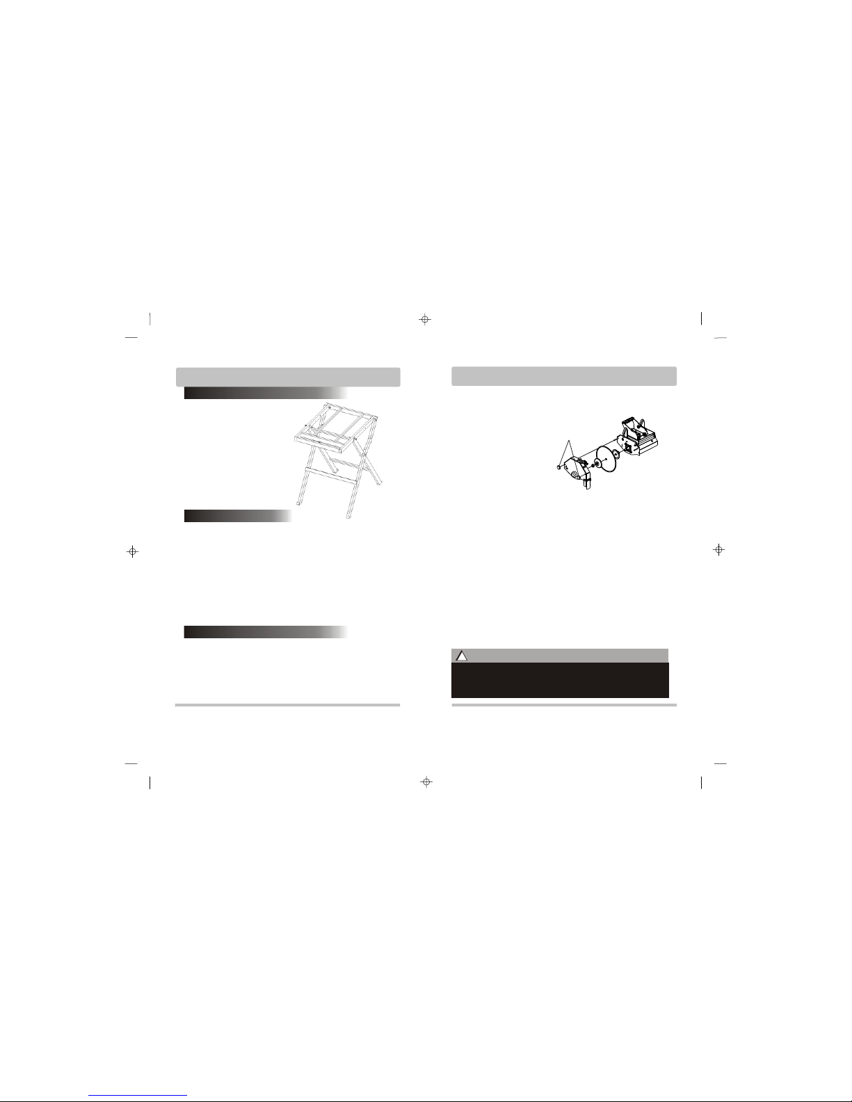
Assembly & Set-Up
1. Remove the carton box cover
from the wooden frame.
2. Remove saw from the crate.
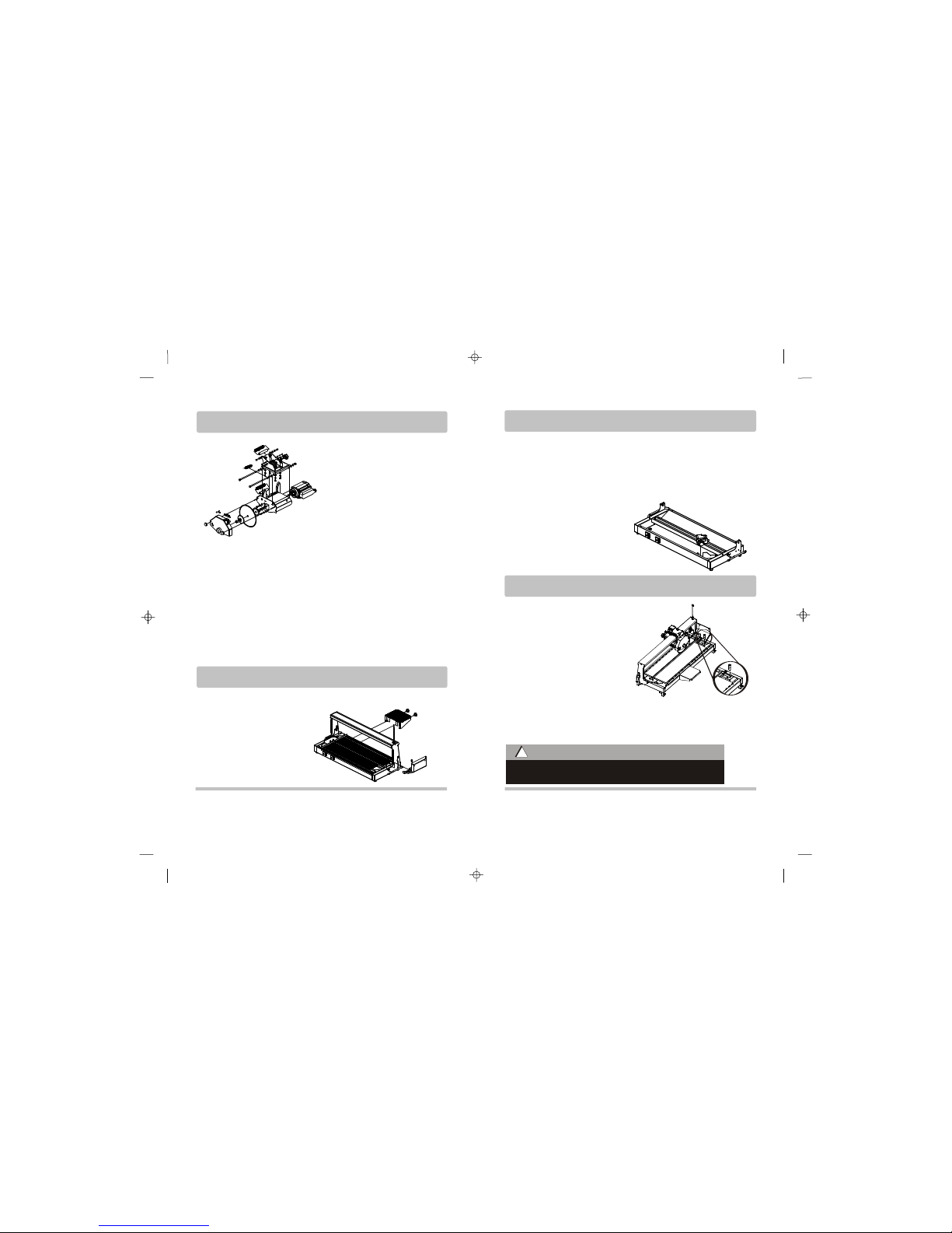
3. Loosen the lock knob on top
of the cutting head.
4. Install the side extension
table, side splash guard and
back splash guard.
5. Install the spring holder on
top of the sliding rail to hold the
power cable and the water hose.
6.Fill the tray with water before
operating the saw.
General Safety Rules Unpack, Assembly & Set-Up
4
3
Unpack
Health Warnings: