62mm
2.44in
62mm
2.44in
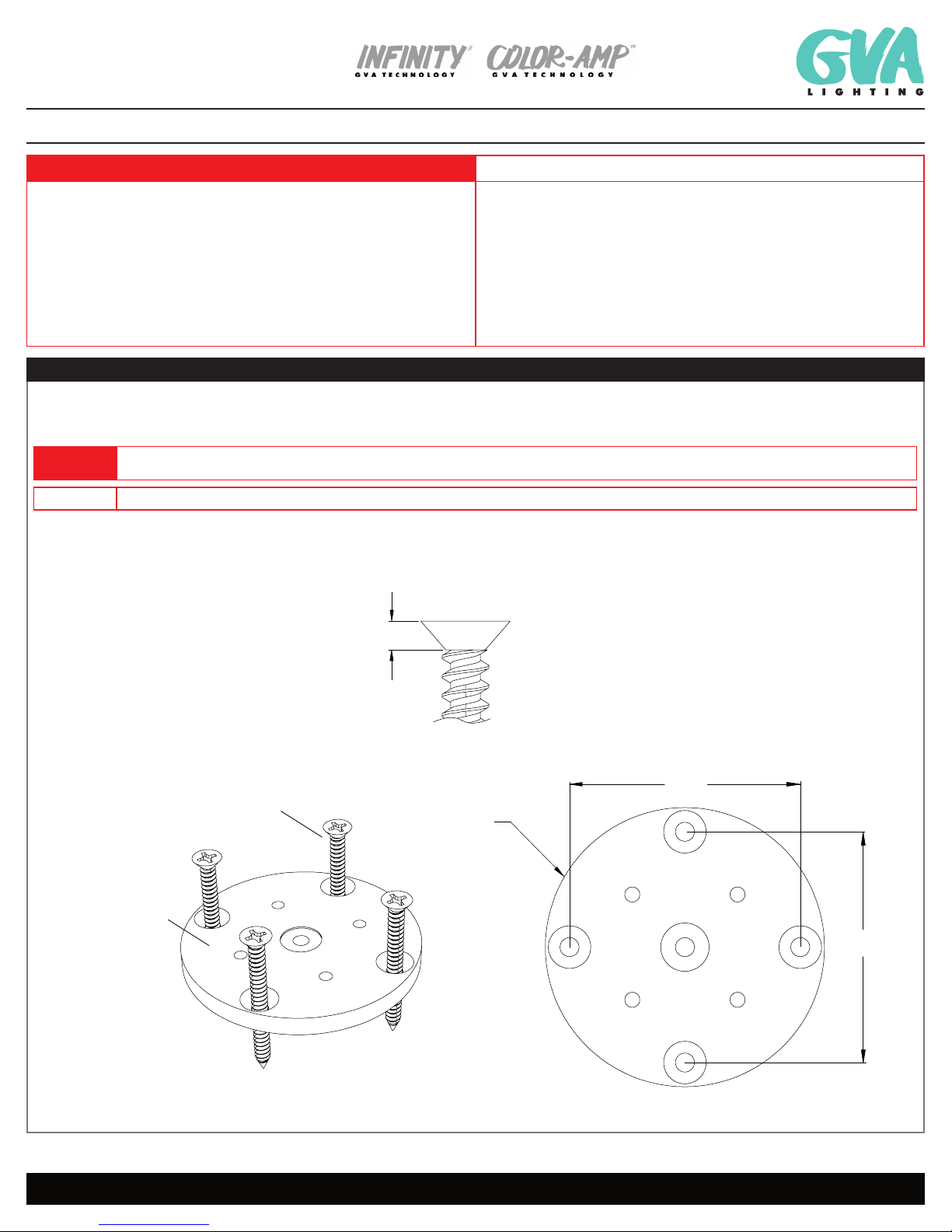
Ø 75 mm
2.95 in
M5 OR #10 SCREW
REQUIRED HARDWARE:
M5 OR #10
FLATHEAD SCREW
(not supplied)
121514 / 121515
MOUNTING PLATE
3.6mm
.14in
Maximum head height:
3.6mm (.14in)
1A
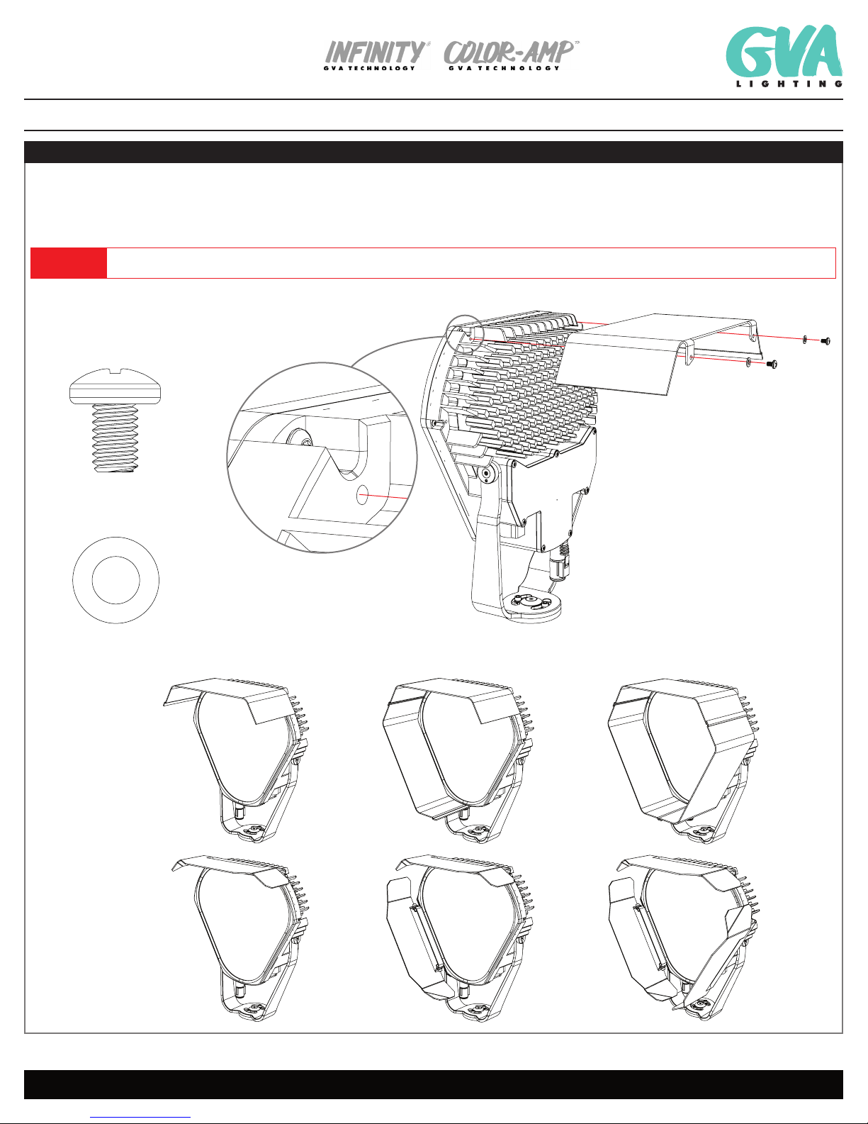
Architectural Spot and Flood Light INSTALLATION GUIDE
GVA Lighting, Inc. 3400 Ridgeway Drive, #14 Missisauga, Ontario L5L 0A2
IG, FL100, 16-09-20 | Page 2 / 7
Specifications are subject to change without notice. Every effort has been made to ensure that the information provided in this manual is accurate.
GVA Lighting Inc. is not responsible for printing or clerical errors. Refer to www.gvalighting.com for additional information.
F L10 0 TM
WARNING CAUTION
Do not attempt to install or use Luminaire until you read and understand this guide and
safety labels.
Luminaires must be installed by a qualified professional in accordance with all national and
local electrical and construction codes and regulations.
Ensure that main power supply is OFF before installing or wiring luminair(s).
Do not exceed specified voltage and current input.
Do not use luminaires with a damaged lens, body, or cable.
Not heeding cautions may result in a hazardous situation which can cause equipment and
property damage, personal injury, or death.
Do not exceed the specified voltage and current input.
Do not exceed the maximum number of specified fixtures in a light run. Doing so will result
in a current overload.
GVA Luminaires have no serviceable parts. Do not attempt to open the units.
Do not hot swap! Ensure power supply is off before connecting or disconnecting fixtures.
Do not stare into beam or view directly with optical instruments.
Unauthorized feild repairs will void warranty.
1. MOUNTING PLATE INSTALLATION
1.1. Install mounting plate in desired location using 4 x NO.10 flathead screws (or equivalent) suitable for the mounting surface. See Diagram 1A to mark holes
prior to installation, if necessary.
WARNING Use mounting hardware suitable for the mounting surface. Use of innappropriate hardware may result in dismounting of the bracket and can result in equipment
damage, injuries, and death.
CAUTION Failure to select the appropriate hardware may result in the screw heads not being flush with the mounting profile which will hinder the installation of the fixture.