NM190 - page 4
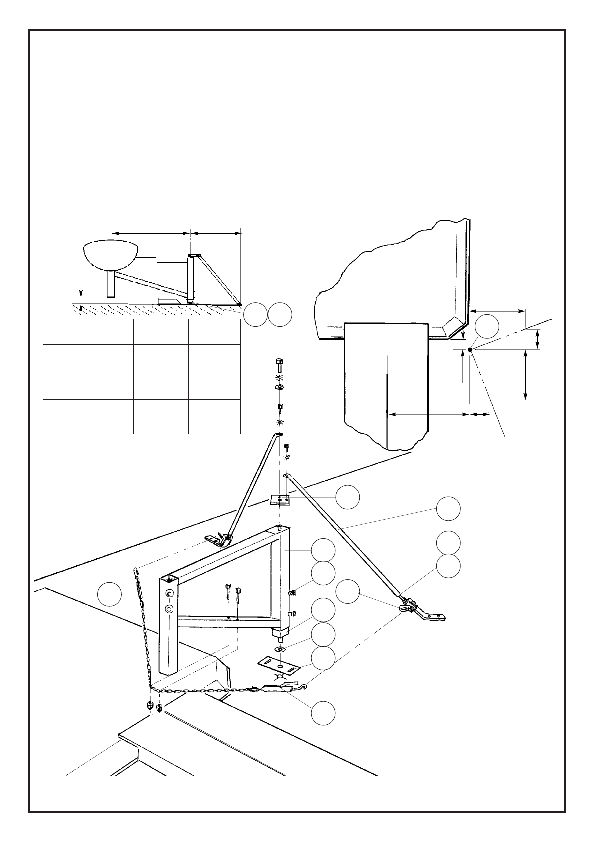
FIG. 7
110
70
100
1100
1100
200
FIG. 9
III . FLOOR/WALL MOUNTED FOLDING EXTENSION (REF.: 3425)
3.1. Preparing and fastening the low pivot (8) to the floor and the wall plate (14):
1– Trace the position (P) of the slide pivot (7) on the floor as shown in figures 7 and 8(Make sure the wall is
perpendicular: 100 mm offset from the line of the top plate).
2– Drill a ø 20 mm hole 20 mm deep (because the slide pivot (7) goes into the floor).
3– Place the low pivot (8) in position and fix it to the floor using the 2 chemical plugs provided.
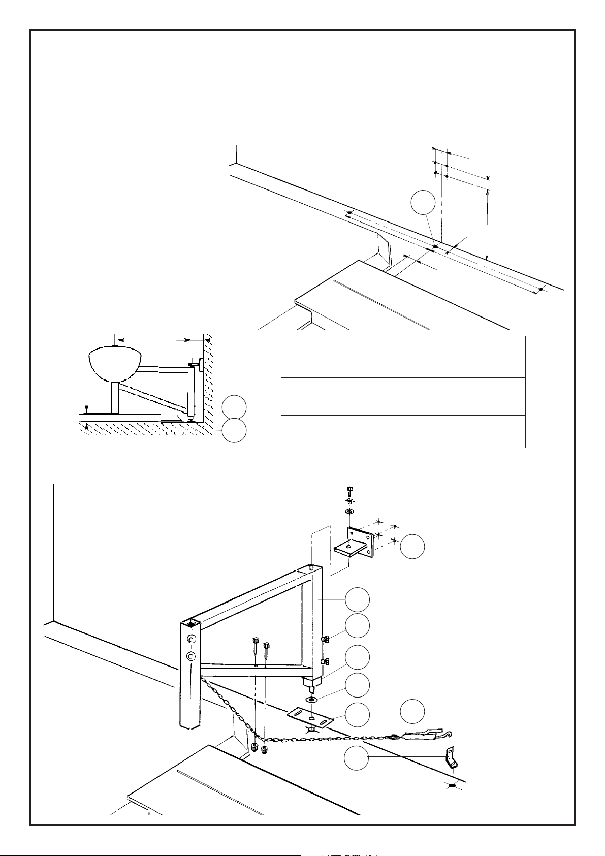
4 – Draw a vertical line on the wall as shown in figure 7.
5 – To position the plate at height "A", use height "H" given in the table in figure 8.
6 – Draw the position of the stay mounts
as shown in figure 7.
7 – Fix the plate (14) with the expansion
3.2. Mounting and adjusting the
extension (6):
1– Slide the extension (6) pivot (7) in the
low pivot (8) with a ø20 washer (5) in
between as shown in figure 9.
2– Adjust the extension, then tighten the
screws (25) locking the pivot slide (7).
3– Fix the top of the extension (6).
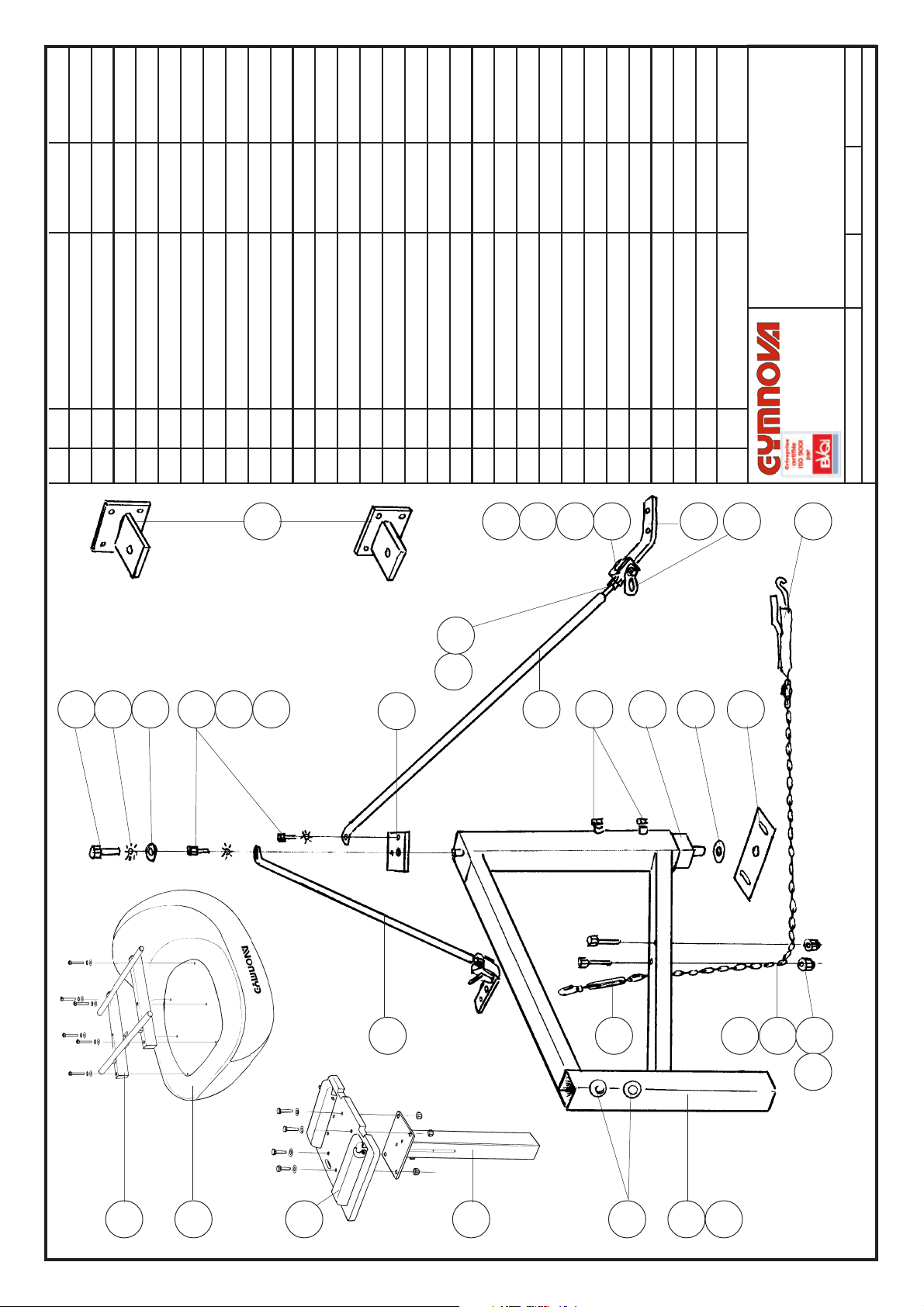
7
8
6
25
5
28
14
26
3.3. Fitting the stays (9):
1 – Place the extension (6) in operating position.
2– Hook the quick-release tensioner (28) on the
track side.
3 – Fix the chain under the extension (6) threading
the 2 screws (18) through its links.
4 – Hook the turn-buckle tie (27) on the other side,
then attach the chain to it, adjusting its length.
5– Adjust the position of the extension and set the
tension of the stays (9) using the quick-release
tensioner (28) and the turn-buckle tie (27).
Warning: Do not tension the stays
with the quick-release tensioner
open.
Landing area
FIG. 8
H (wedging/floor) = h (track or pit) + 20mm
7
8
1500
H
100
Vaulting axis
P
A
Warning: for an acrobatic track with
pit, the body of the vaulting table is
actually 10 cm higher than the
graduation on the foot.
bolts provided.
8– Fix the stay plates (26) with 2 chemical plugs.
H(wedging/floor)
60 mm
160 mm
250 mm
Evolution track
Acrobatic track
or exercise floor
Landing pit
or tumbling
h(track or pit)
40 mm
140 mm
200 mm
A(top plate)
745 mm
845 mm
935 mm