Gyraf Audio Gyratec 10 Vari-Mu User manual

Gyraf Audio Gyratec 10 Vari-Mu Compressor
Gyraf Audio Gyratec 10 Vari-Mu stereo tube compressor.
Preliminary user manual, 12. June 2003.
The Gyratec 10 is a true tube stereo compressor based on the Vari-
Mu VCA principle. This method - controlling the gain by the means
of varying the DC working point of a tube differential pair, and
hence the Mu, is much faster than the electro-optical method used
in our G3, but also less subtle sonically. The Vari-Mu principle
is known from e.g. the classic Universal Audio UA176, the RCA
BA6A, or the legendary Fairchild 670.
In use:
First of all, when turning on the compressor, allow the unit to
heat up for ten to fifteen minutes - to get the tubes stabilised
in their working temperature. The sound and operating levels will
change somewhat within this period.
The controls on the Gyratec 10 are as follows:
The inputs are floating transformer balanced, 10K Ohm "bridging"
type, meaning that we don’t load the output of the previous stage
too much. The input connectors are standard XLR jacks, pin 2 hot.
The "bypass" function switch (4) bypasses the unit completely for
reference. The bypass is “hard”, meaning that the input is simply
shorted to output through a gold-plated relay. The light in the
GR-meter will dim a bit when set to bypassed, in order to let you
1

know what you did. If you wish to use the unit as a straight line
preamp, but with bypassed compression, the compression can be ful-
ly disabled by turning the Ratio knob (3) fully counter-clockwise,
or turning the Threshold pot (2) fully clockwise.
The Bypass knob is also where the sidechain high-pass filter is
controlled if your unit is a G10/Hpf. First step fully CCW is by-
pass, next is switched in with no filtering, and the last three
steps are filtering the sidechain signal at 6dB/oct at 80, 160 and
300Hz. The purpose of this filter is to allow you to compress
bass-heavy material without getting too many artefacts from the
low-frequency content triggering compression (a.k.a. “pumping”)
The input level control (1) is positioned right after the input
transformers, allowing you to control the input level for the
first variable gain stage - the "drive" for the compressor. Unity
gain is obtained when input and output gains are set roughly at
their two o’clock positions.
The Threshold pot (2) controls at what level the compression will
set in. Turning counter-clockwise will select a lower start point,
resulting in more compression. When turned fully clockwise, the
compression is deactivated.
The Ratio pot (3) controls the amount of compression in relation
to changes in the input level, that is, for the part of the signal
that exceeds the threshold value that is set. Setting Ratio fully
counter-clockwise will deactivate compression.
The Attack pot (7) controls the time the compressor takes to react
to a rising input level.
The Release pot (8) controls the amount of time it takes from the
input signal falling below threshold, to the gain reduction being
returned to unity.
The Output level pot (9) controls the signal level to the output
driver stage and the output. The output impedance is less than 1K
Ohm, and is - like the input - floating transformer balanced.
The lighted GR-meter (5) is reflecting the ongoing gain reduction
- monitoring the vari-mu stage - allowing you to check the state
of things at a quick glance. At heat-up the meter slowly rises to
a position somewhere near the clockwise end of the scale, and gain
reduction is read out as counter-clockwise movement.
The meter offset (at the top end of the scale) will be varying a
bit, depending on heat-up, average signal level, meaning that the
zero point will vary a bit depending on a variety of factors. The
meter zero can (if needed) be adjusted by the trimmer at the
bottom centre at the front of the meter frame.
2

Technical:
This compressor is based on two closely-matched differential pair
7ES8 /PCC189 remote-cutoff triodes, differentially feeding two
6DJ8 /ECC88 cathode follower output stages. No feedback is used in
the signal path, and the topology is pure class-A all the way
through the unit. Lundahl audio transformers with internal elec-
trostatic shielding are used for both in- and output interfacing,
giving a true floating input impedance of about 10KOhm, and an
output impedance of less than 1KOhm.
This unit was originally intended for use with our analogue tape
recorders, which means that the optimum operating levels are
around that of +4dBu – and at this point you still have some 10dB
up to the point where the unit starts to get tired, which happens
around 15Vpp AC output – and then some before it starts sounding
bad. This means, however, that you should consider checking your
levels if you’re running a modern-day DAW, which often comes fac-
tory set to extremely-high levels like +24 or +28 for 0dBfsd.
Those kinds of levels are aimed at keeping a good safety-margin
before running into digital-clip, but at the same time it’s common
practice (for a good reason) to try getting as close to clip as
possible. A good level for use with the G10 (and for most analogue
gear in general) is somewhere around +10dBu for 0dBfsd (full scale
digital)
Our audio path consists of ONLY transformers, tubes, and passive
components, and is true-differential (balanced) all the way from
input to output.
The sidechain and power supply circuits are solid-state based
though. The sidechain senses the incoming signal, rectifies and
times the voltages, and controls the DC voltage applied to the
differential input stage in order to set the quiescent current of
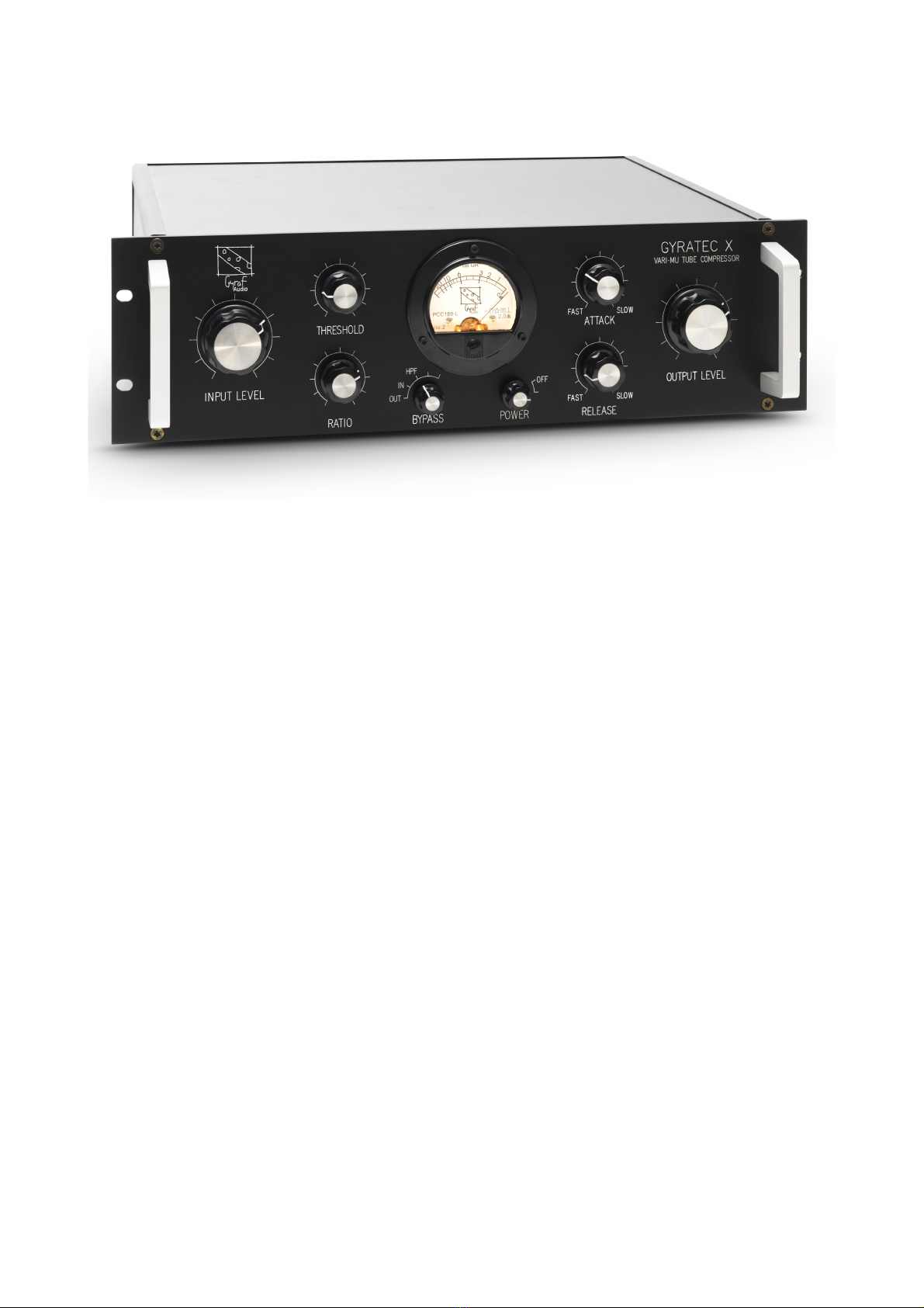
the stage, reflecting on the µ- and thus on the stage gain. The
quiescent current in the input stage is monitored by the front
panel meter, which then reads stage gain.
We use two types of tubes in the G10: The vari-mu set are
7ES8/PCC189 remote cutoff dual triodes, and the output driver set
are 6DJ8/ECC88 medium-mu dual triodes. Both types are still fairly
available today, so don’t worry too much about availability for
the future. These tubes should last for at least a couple of years
- and often a lot longer than that. If and when changing tubes,
contact Gyraf Audio for instructions on proper adjustment of the
unit.
Although semiconductors and op amps are used in this unit, they're
confined to power supply and sidechain functions. At no time will
your audio pass through anything but transformers, tubes and
passives. So - as with the rest of our product range - we're
talking REAL tube audio here..
3

Important notice:
Do not open this unit, as there are really high - potentially
lethal - voltages present inside. Refer servicing to qualified
personnel. If trimming the unit, it is of primary importance to
use insulated tools, as lethal voltages are present on exposed
surfaces related to the trimming procedure. Do NOT try this
yourself, unless you’re absolutely sure what you’re doing.
You can safely remove the four rubber feet if you wish to mount
this unit in a tight rack - please save the feet for future use.
NOTE: The feet are the ONLY part that can safely be removed. Do
not loosen any other screws!
For long tube life, switch off unit when not in use. Don’t leave
it on all the time - it won’t suffer from being turned on and off
regularly.
This unit operates from 220-230V AC, consumes about 35W, and the
mains fuse is a 630mA slow-blow type. For the US-version, marked
“This unit is wired for 115V Mains”, the operating voltage is
110-120VAC, and the fuse is a 630mA Slow-blow (“T”) type.
For further questions, comments and wishes, please contact Gyraf
Audio:
e-mail: [email protected]
Web: www.gyraf.dk
Telephone: +45 5129 2769
Address: Gyraf Audio
Haraldsgade 27
DK-8260 Viby J.
Denmark
Europe
Jakob Erland
Gyraf Audio
06. March 2003.
4

Declaration of EU-accordance
I, the undersigned, hereby declare that the following device observes the protectional demands stated in the Council’s
directive 89 336 EEC about electromagnetic compatibility (EMC) and the Low Voltage Directive (LVD).
Identification of device
Category: Audio Compressor Limiter
Make: Gyraf Audio
Model type: Gyratec X Vari-mu tube compressor
Name and address of the undersigned:
Jakob Erland
Gyraf Audio
Feedback Recording
Haraldsgade 27
DK8260 Viby J.
Standards founding this declaration:
EN 55013, EN 55020, EN 61000-3-2, EN 61000-4-2 and EN 60065.
emarks:
The CE-mark only states accordance with the EMC-directive 89 336 EEC and the Low Voltage Directive, LVD.
Aarhus, June 2002
6
Table of contents