H. B. Fuller Cyberbond CB LINOP U 500 User manual
Cyberbond CB
LINOP U 500
Operating Instructions
Control Unit for Cyberbond
UV Curing Systems
including Cyberlite 50 S and Cyberlite 4 S

Cyberbond CB
Page 2Cyberbond LINOP U 500 / Operating Instructions
LINOP U 500
The described Equipment
Control Unit LINOP U 500
LED lamp LINOP Cyberlite 50 S Multiplier/Amplifier BoosterPack 13 A
LED lamp LINOP Cyberlite 4 S Multiplier LINOP Splitter

Cyberbond CB
Page 3Cyberbond LINOP U 500 / Operating Instructions
LINOP U 500
Table of contents
1 Advance Information ........................................................................................................................... 4
1.1 LINOP U 500 ....................................................................................................................................... 4
1.2 Cyberlite 50 S and Cyberlite 4 S LED lamps ........................................................................................ 4
1.3 Technical data LINOP Cyberlite 50 S.................................................................................................... 5
1.4 Technical data LINOP Cyberlie 4 S....................................................................................................... 5
2 Safety precautions and warning notice................................................................................................ 6
3 General information ............................................................................................................................ 6
3.1 Symbol information............................................................................................................................. 6
3.2 CE Compliance.................................................................................................................................... 7
4 Structure............................................................................................................................................. 8
4.1 Cyberlite 50 S without BoosterPack (LIN-Bus standard)....................................................................... 8
4.2 Cyberlite 50 S with BoosterPack (LIN-Bus standard)............................................................................ 9
4.3 Cyberlite 4 S without Splitter............................................................................................................. 10
4.4 Cyberlite 4 S with Splitter.................................................................................................................. 10
5 Installation with LIN-Bus (only LINOP U 500 in combination with Cyberlite 50 S)................................ 10
5.1 Installation without BoosterPack ....................................................................................................... 10
5.2 Installation with BoosterPack ............................................................................................................ 10
5.3 Erase of the lamps ............................................................................................................................ 11
5.4 Pairing of lamps................................................................................................................................ 11
5.5 How to work with paired lamps......................................................................................................... 11
6 Instruction with Cyberlite 4 S (no LIN-Bus) ........................................................................................ 11
7 Navigation ........................................................................................................................................ 12
7.1 Main Menu........................................................................................................................................ 13
7.2 Device Menu (LED Lamp Menu) ........................................................................................................ 13
7.3 Information Menu.............................................................................................................................. 14
8 Saving and loading ........................................................................................................................... 14
9 To start illumination time................................................................................................................... 15
10 Showing Errors ................................................................................................................................. 15
11 Interfaces.......................................................................................................................................... 16
11.1 DC 24 V IN ........................................................................................................................................ 16
11.2 LIN-Bus ............................................................................................................................................ 16
11.3 I/O 1...3 ............................................................................................................................................ 16
11.4 FT..................................................................................................................................................... 16
11.5 Digital-Interface DC 24 V................................................................................................................... 17
11.6 Equipotential bonding conductor connection (PE) .............................................................................. 17
12 Technical data LINOP U 500 .............................................................................................................. 18
13 LINOP Item Numbers......................................................................................................................... 19
Cyberbond CB
Page 4Cyberbond LINOP U 500 / Operating Instructions
LINOP U 500
1 Advance Information
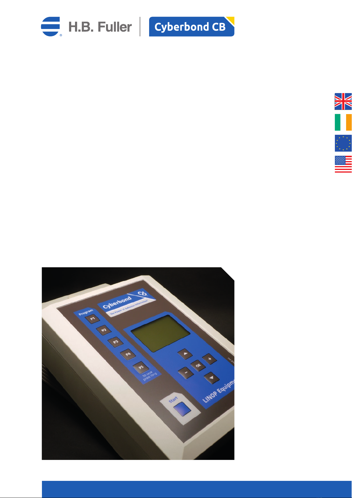
1.1 LINOP U 500
The LIN-Bus controlled LINOP U 500 can be chosen as a table unit or is taken when directly used
in a PLC controlled production line. Sensor technique helps exact fault finding in the range of lighting.
LINOP U 500 is optional equipped with a flexible arm.
The line of LINOP series consists of various, similar-looking devices with different functions and options
for connections. Please check which unit is to be used before commissioning.
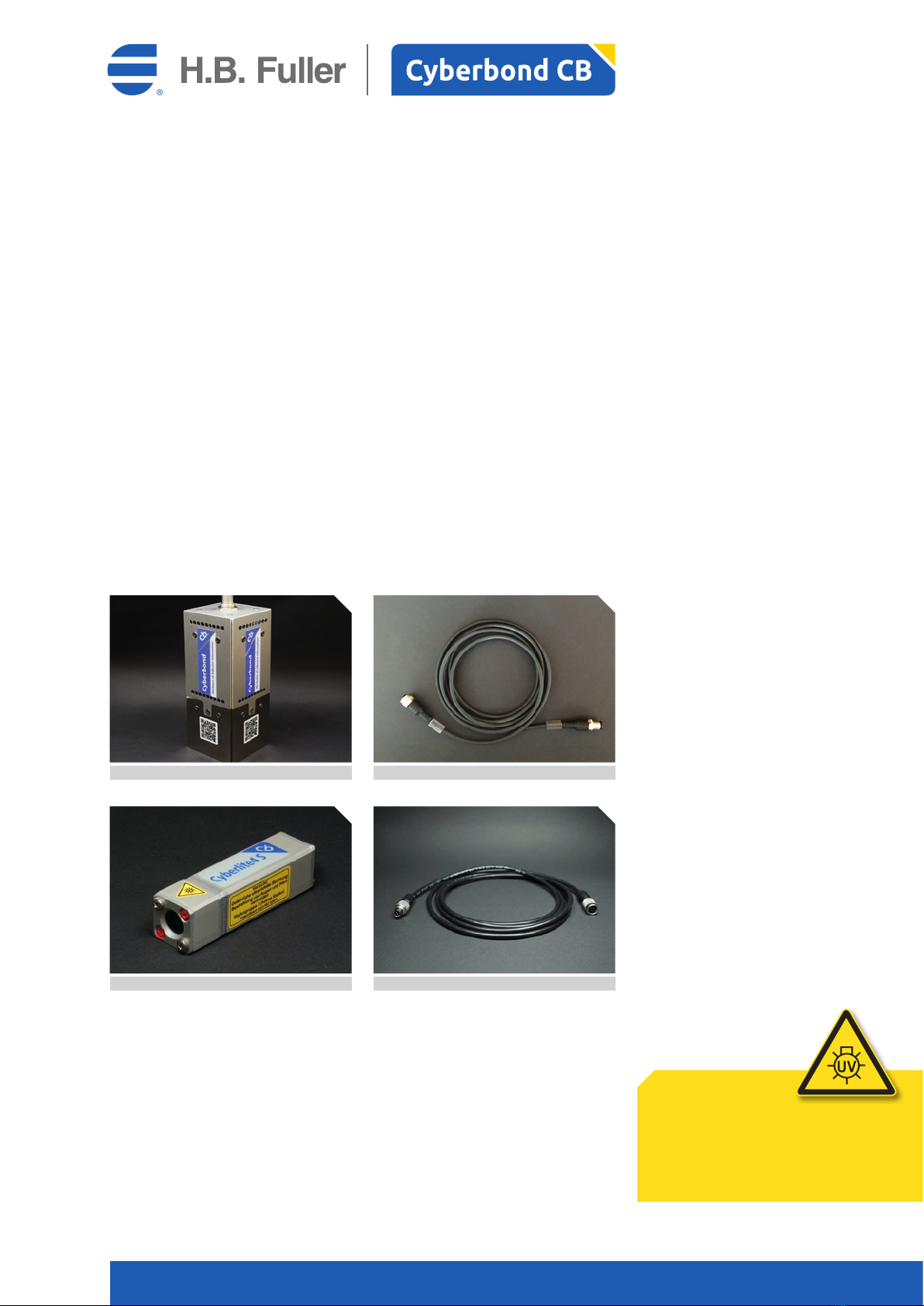
1.2 Cyberlite 50 S and Cyberlite 4 S LED lamps
LINOP U 500 is designed to use Cyberbond LED lights:
• Cyberlite 50 S
• Cyberlite 4 S
In order to connect the LINOP U 500 with one of the Cyberlite lamps you need a cable each; but be careful,
different cables are needed. For the connection of different lights we assume no liabilities.
Cyberbond LED lights are equipped with the following warning. [see right column]
Attention!
Dangerous ultraviolet radiation
Avoid irradiation of eyes and skin
At-risk group 3 (high risk)
Classified according to IEC 62471
LINOP Cable 80194
LINOP Cord 80192
Cyberlite 4 S
Cyberlite 50 S

Cyberbond CB
Page 5Cyberbond LINOP U 500 / Operating Instructions
LINOP U 500
1.3 Technical data LINOP Cyberlite 50 S
1.4 Technical data LINOP Cyberlie 4 S
LINOP Cyberlite Cyberlite 4 S
Peak wave length approx. 395 nm
Light spectrum approx. 380 to 440 nm
Intensity of light, distance 10 mm approx. 350 mW / cm2
Intensity of light, area approx. 20 x 20 mm approx. 270 mW / cm2
Intensity of light, area approx. 60 x 60 mm approx. 14 mW / cm2
- of that in UVA range (380 to 400 nm) approx. 1/3
- of that in visible light range (> 400nm) approx. 2/3
Working temperature – 25 °C to + 60 °C
Power input 5 W
Limits 1.000 mA Peak
Control unit LINOP U 400, 1 exit 4,6 V / 600 mA – 2,76 W
Life expectancy > 15.000 hours
Housing material Aluminium
Weight approx. 65 g
Measurements approx. 70 x 20 x 20 mm
LINOP Cyberlite 50 S
Peak wave length approx. 395 nm
Light spectrum approx. 380 bis 440 nm
Intensity of light, lower edge mirror approx. 210 mW / cm2
- of that in UVA range (380 to 400 nm) approx. 1/3
- of that in visible light range (> 400nm) approx. 2/3
Working temperature – 25 °C to + 60 °C
Power input approx. 40 W
Control unit LINOP U 500, 1 exit 24 V / 2000 mA
Life expectancy > 15.000 hours
Housing material Aluminium
Weight approx. 800 g
Measurements approx. 64 x 64 x 183 mm
Cyberbond CB
Page 6Cyberbond LINOP U 500 / Operating Instructions
LINOP U 500
2 Safety precautions and warning notice
•
The unit must always be operated according to the manufacturer’s instructions for use.
• The unit must be operated by, staff who have been trained and who are authorised.
They must know the operating instructions and operate the unit accordingly.
• The operation manual must be kept in a safe place easily accessible to each user.
• Illegal changes and the use of spare parts as well as accessories that have not been sold or recommended
by the manufacturer of this unit can cause fires, electric shocks and injuries. These measures lead
to an exclusion of liability and the manufacturer assumes no liability.
• Basis for the guarantee of the manufacturer is the version of the warranty policy for the unit
at the time of purchase. We assume no liability for unsuitable or an incorrect manual or automatic
adjustment of parameters of the unit. We also assume no liability for an improper use of the unit.
• Repairs must be carried out by the manufacturer
• The user is responsible for placing and installing the dosing unit according to the approved technical
regulations of the country or area concerned.
3 General information
3.1 Symbol information
The hazard and safety symbols used in this document are illustrated as follows.
[see right column]
Attention!
Safety precaution for device:
Disregard can lead to material damage and affect
the reliable functioning of the device.
Danger!
Safety precaution for health:
Disregard can lead to personal and material damage
and affect the reliable functioning of the device.
Note!
Important information:
This symbol points to additional information
that describes the instructions in a more detailed
manner. This allows for a better understanding
of the operating procedure of the device
!
!
i

Cyberbond CB
Page 7Cyberbond LINOP U 500 / Operating Instructions
LINOP U 500
3.2 CE Compliance
Cyberbond confirms:
CE Compliance for LINOP dosing and curing systems
M 600, M 1500, M 2000, U 500, Cyberlite 4 S, Cyberlite 50 S, BoosterPack 13 A, Splitter
Cyberbond Europe, the distributor of its in-house developed dosing and curing systems,
hereby certifies that these products comply with all safety-related requirements
according to the following applicable EC Regulations:
Council Directives
• Electromagnetic Compatibility (EMC) Directive 89/336/EEC
Low Voltage Directive 2014/35/EC
Standards and technical specifications
• Radio interference voltage
EN 50081-1, VDE 0839 sect. 81-1
• Radio noise emission
EN 50081-2, VDE 0839 sect. 81-2
• Electrostatic discharge immunity test
according to IEC 1000-4-2, EN 61000-4-2, VDE 0847 sect. 4-2
• Interference resistance against high-frequency electromagnetic fields
according to IEC 1000-4-3, EN 61000-4-3, VDE 0847 sect. 4-3
• Electrical fast transient/burst immunity test
according to IEC 1000-4-4, EN 61000-4-4, VDE 0847 sect. 4-4
• Immunity to Surge voltages
according to IEC 1000-4-5, EN 61000-4-5, VDE 0847 sect. 4-5
• Immunity to conducted interference,
induced by high-frequency fields
according to IEC 1000-4-6, EN 61000-4-6, VDE 0847 sect. 4-6
LINOP Equipment corresponds to the EC Directive 2011/65/EU (ROHS 2).

Cyberbond CB
Page 8Cyberbond LINOP U 500 / Operating Instructions
LINOP U 500
4 Structure
Control Unit:
•LINOP U 500 for Cyberlite 50 S or Cyberlite 4 S LED lamp
Lamp systems with self-regulating intensity and LIN-Bus standard:
•Cyberlite 50 S LED lamp with 4 power LEDs
•BoosterPack 13 A Multiplier/Amplifier to connect up to 5 Cyberlite 50 S
Lamp systems without self-regulating intensity and without LIN-Bus standard:
•Cyberlite 4 S LED lamp with 1 power LED
•Splitter Multiplier/Amplifier to connect up to 3 Cyberlite 4 S
There are several options. By means of the LIN-Bus connector you are able to connect 1 Cyberlite 50 S alone
with the LINOP U 500. In case you want to connect several lamps, you must integrate the so called Booster-
Pack. With this you can run up to 5 Cyberlite 50 S lamps; plus you can link it with a further BoosterPack.
The drawing below tries to describe this process.
If you want to connect the Cyberlite 4 S lamp, this can be done directly in combination with the LINOP U 500.
Up to 3 lamps can be linked. By means of the so called Splitter up to 9 LED lamps can be combined parallel.
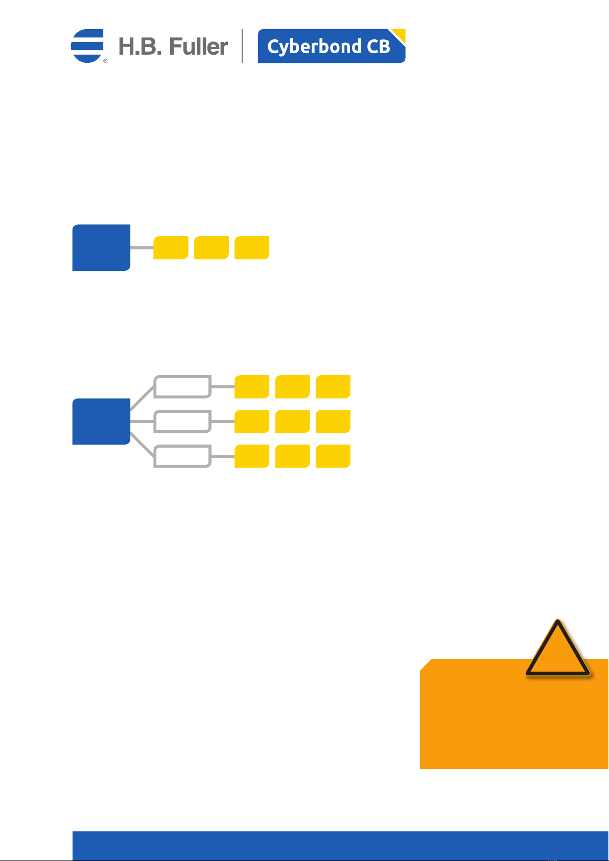
4.1 Cyberlite 50 S without BoosterPack (LIN-Bus standard)
In case just 1 Cyberlite 50 S is needed, I simply connect this LED lamp
with the LINOP U 500 control unit.
LINOP U 500
w. Power Supply
L1
Cyberbond CB
Page 9Cyberbond LINOP U 500 / Operating Instructions
LINOP U 500
4.2 Cyberlite 50 S with BoosterPack (LIN-Bus standard)
A BoosterPack is an electrical amplifier as well as a manifold for various lamps. The first BoosterPack must be
connected with the control unit LINOP U 500. Then the BoosterPack can control up to 5 Cyberlite 50 S lamps.
The current supply comes separate, not from the control unit. In case more lamps are required you connect
the first BoosterPack with a second one. The current supply again is ensured separately, a second control unit
LINOP U 500 is not necessary. Last but not least a third BoosterPack could be connected with the second one,
so that you are able to run in maximum 15 Cyberlite 50 S lamps with 1 control unit LINOP U 500 and
3 BoosterPacks.
LINOP U 500
LIN-Bus
LIN-Bus
LIN-Bus
DC 24V / 16A IN
DC 24V / 16A IN
DC 24V / 16A IN
Power Supply
Power Supply
Power Supply
BoosterPack 1
BoosterPack 2
BoosterPack 3
L1
L1
L1
OUT1
OUT1
OUT1
IN
IN
IN
L4
L4
L4
OUT4
OUT4
OUT4
L5
L5
L5
OUT5
OUT5
OUT5
OUT6
OUT6
OUT6
L3
L3
L3
OUT3
OUT3
OUT3
L2
L2
L2
OUT2
OUT2
OUT2
for BoosterPack
for BoosterPack
for BoosterPack
no Power Supply needed
Cyberbond CB
Page 10Cyberbond LINOP U 500 / Operating Instructions
LINOP U 500
4.3 Cyberlite 4 S without Splitter
In case you want to work with the Cyberlite 4 S LED spots, a LIN-Bus controlled system is not available.
The control unit LINOP U 500 can be equipped with in maximum 3 Cyberlite 4 S lamps.
4.4 Cyberlite 4 S with Splitter
In contrast to the BoosterPack the Splitter is just a manifold in order to connect more lamps. The LINOP U 500
can take up to 3 Splitters; each Splitter can run up to 3 lamps so that you can control up to nine lamps with
1 LINOP U 500 and 3 Splitters.
5 Installation with LIN-Bus
(only LINOP U 500 in combination with Cyberlite 50 S)
Before a system is delivered it is very important to pair all lamps needed.
5.1 Installation without BoosterPack
Without BoosterPack just one Cyberlite 50 S can be connected with the control unit LINOP U 500. The LINOP
U 500 is connected with the 24 V power supply unit. The system can be switched on/off via the On/Off switch.
5.2 Installation with BoosterPack
By means of the BoosterPack 13 A up to 5 Cyberlite 50S per booster can be connected. Furthermore
the LINOP U 500 control unit can take up to 3 BoosterPacks. Thus you can run the system with maximum
15 lamps. The BoosterPack 13 A supplies 13 Ampere, each Cyberlite 50S needs 2.5 A, thus 5 lamps go
with 1 BoosterPack 13 A.
In this constellation the On/Off switch of the Booster Pack is important, not the one of the LINOP U 500 control
unit. You also don’t need a 24 V Power supply unit, because the LINOP U 500 gets its power
from the BoosterPack.
LINOP U 500
w. Power Supply
L1 L2 L3
LINOP U 500
w. Power Supply
L4
L1
L7
L5
L2
L8
L6
L3
L9
LINOP Splitter 1
LINOP Splitter 2
LINOP Splitter 3
Attention!
Safety precaution for device:
All Cyberlites 50 S lamps have to be paired
beforehand [Chapter 5.4]. The order how to connect
the lamp with the booster port is not relevant.
The shown positions in the menu reflect the order
during the pairing process.
!
Cyberbond CB
Page 11Cyberbond LINOP U 500 / Operating Instructions
LINOP U 500
5.3 Erase of the lamps
It can be necessary to erase Cyberlite 50 S lamps from the LINOP U 500 control unit in order to clear
the memory, because a lamp will be replaced by another one. If you don’t delete the former lamp,
the system would try to seek it and would give you a defect note.
To erase a lamp you have to do the following:
1. Switch off the system (in booster mode via BoosterPack, in standard mode via LINOP U 500).
2. Disconnect all cables from the LED lamps.
3. Push switch “P1“ and keep it pressed down.
4. Switch on the system while keeping the „P1“ switch down.
5. Release the “P1“ switch when sytem is on.
5.4 Pairing of lamps
All lamps have to be paired with the control unit one time before use. Therefore you have to connect the
lamps with the BoosterPack at an interval of 10 seconds one by one. In the case you just need 1 lamp,
there is no need to use a booster and you can connect the lamp directly with the control unit LINOP U 500.
5.5 How to work with paired lamps
In case lamps are paired all lamps can be kept connected with the BoosterPack or the LINOP U 500. All lamps
can be connected or disconnected while the system is running. If you disconnect a paired lamp an error note
on the display can be seen “Device X not found“. If you now confirm with “OK” all is running again.
6 Instruction with Cyberlite 4 S
(no LIN-Bus)
You can run up to 3 Cyberlite 4 S directly with the control unit LINOP U 500, a pairing of the lamps
is not necessary respectively possible.
The lamp connected with port I/O 1 is shown in the display as lamp 01 etc. (I/O 2 = lamp 02, I/O 3 = lamp 03).
In order to run the whole system you need to use a 24 V power supply pack
and use the main switch “ON/OFF”.
If you also use the Splitter you are able to run up to 3 lamps per Splitter/port. In this case the individual sur-
veillance of intensity and temperature is not working anymore. The whole system takes in maximum
3 Splitters respectively 9 Cyberlite 4 S lamps.
Attention!
Safety precaution for device:
Take care that no lamps are connected
with the LIN-Bus.
Attention!
Safety precaution for device:
Never connect more than 1 not paired lamp at
a time with the BoosterPack. If the lamp is finally
paired can be checked via the main menu. Let us
assume you have already paired 3 lamps. You just
scroll down to lamp position 3. If you connect now
the forth lamp an arrow showing down can be seen
and you can scroll down one more position.
The shown position in the menu is just the order of
how you paired the system.
!
!

Cyberbond CB
Page 12Cyberbond LINOP U 500 / Operating Instructions
LINOP U 500
7 Navigation
To manage the navigation within the menu you use the keys “Ü“, “Û“, “+“ = right and “-“ = left.
By pushing the key “OK” you are able to change to different menu levels. In each level the individual figures
(time, intensity etc.) can be chosen and confirmed by using the keys“+“ and “-“. By pushing again the “OK”
button you are changing the menu level.
Note!
Important information:
The arrows at the top edge of the display
show in which direction you navigate.
Navigation is just possible in case lamps
are connected and paired.
i
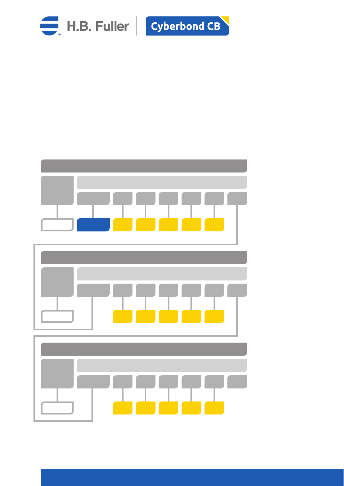
Main Menu
Device 01
[Device Menu]
Device 01
[Information Menu]
Device 02
[Device Menu]
Device 15
[Device Menu]
Device 02
[Information Menu]
Device 15
[Information Menu]
The arrows in the top of the display give directions in which other menu level you can navigate. By pushing
“OK” you come to the adjustment level <…> of the chosen menu. If you push the “OK” button again you
leave the actual adjustment level and can switch between the various menus.
Cyberbond CB
Page 13Cyberbond LINOP U 500 / Operating Instructions
LINOP U 500
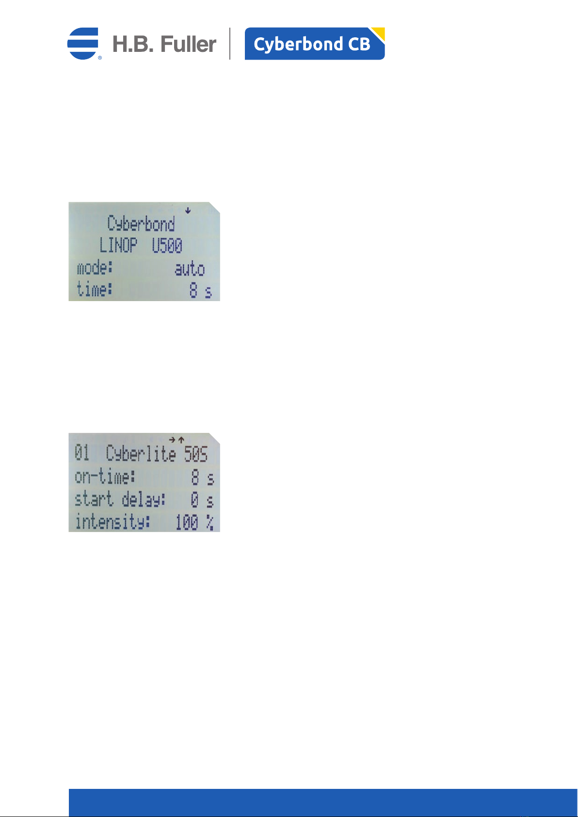
7.1 Main Menu
By pushing the “OK” button you reach the <auto> or <man> mode. By pushing the “+“ and “-“ keys you can
change this mode.
auto: after pushing the “Start“ button the con-
nected lamps will illuminate for the predetermined
time. The time counts down to zero.
man.: after pushing the “Start“ button the con-
nected lamps will illuminate as long as the “Start“
button is held. The time counts up.
By pushing the “Ü“ arrow you switch to the next connected lamp.
7.2 Device Menu (LED Lamp Menu)
The menu shows the before fixed figures. By pushing the “OK” key you are able to change these figures
by using the keys “Ü“ und “Û“. The figure you want to change is shown in brackets <…>.
The keys “-“and “+“ decrease or increase the actual valuefigure. By pushing again “OK” you confirm
the figure and are able to change again between the several menus.
01: lamp No. 02, 03, …, 15
Cyberlite 50 S: name of connected lamp
on-time: time of illumination
(within Mode <auto>) 1 ... 100 s
start delay: delay of time of illumination
(within Mode <auto>) 1 ... 100 s
intensity: to be fixed intensity of illumination
in percent 0 ... 100 %
By pushing “Û“ you can switch to the before connected lamp or to the main menu
By pushing “Ü“ you can switch to the next lamp if connected
By pushing “+“ = right you are able to switch to the information menu of the lamp

Cyberbond CB
Page 14Cyberbond LINOP U 500 / Operating Instructions
LINOP U 500
7.3 Information Menu
In each information menu you can see the status, the temperature and the intensity of a connected lamp.
These shown values cannot be changed. They will be permanently actualised
01: lamp No. 02, 03, …, 15
Cyberlite 50 S: name of connected lamp
status: <o.k.>all is fine,
<err.> there is an error
temperature: actual measured temperature
of the lamp
intensity: actual measured intensity
of the lamp
By pushing “Û“ you can switch to the before connected information menu or to the main menu
By pushing “Ü“ you can switch to the next information menu
By pushing “-“ = left you are able to switch to the information menu of the lamp
8 Saving and loading
There are 5 storrages spaces available. By using the buttons “P1“…“P5“ you can easily store
and load settings.
By pushing long one of the keys “P1“…“P5“ you store the actual setting. While storing you can see
the symbol <6> in the display. Also you hear a receipt tone.
By just pushing shortly one of the keys “P1“…“P5“ the individual setting is reloaded. Again this process is
documented by the symbol <6> in the display. Also you hear again a receipt tone.
Even if you don’t use the unit for a longer time the settings are saved.
A loaded programme can be seen as e.g. <P1> in the main menu.

Cyberbond CB
Page 15Cyberbond LINOP U 500 / Operating Instructions
LINOP U 500
9 To start illumination time
By working with UV lamps the following hazards and pre-cautions should be considered:
To start the illumination process push the “Start“ button or the connected foot switch [see Chapter 11.4].
Moreover you can also use the interface function in order to start [see Chapter 11.5].
In order to start in the <auto> mode a start impulse is enough to start the whole programme.
In the <man. > mode you have to push the e.g. “Start“ button as long as the programme needs
or as long as you want to illuminate the lamps. Depending on the chosen mode [see Chapter 7.1]
the fllowing will happen:
• The time in the display counts up <man. > or down <auto>.
• The clock symbol <º> can be seen in the display.
• The connected lamps will be gated by using the before fixed values.
• The exit <Busy> switches the voltage of the interface [see Chapter 11.5].
After progress of event the whole system goes back in initial state.
10 Showing Errors
1. line: number of errors.
2. line: kind of error
Device X not found
Device X high temp: too high temperature
Device X intensity: too low intensity
Each signal has to be confirmed with “OK”. During the fault alarm and after having everything confirmed
you can run the system as usual; but it is recommended to investigate the reasons for the error messages
and start a necessary improving process.
Danger!
Safety precaution for health:
• Risk of injury of the eyes and the skin
due to UV rays!
• Wear protecting glasses of the following type:
Protecting level DL7 with filtertype P1008!
• Avoid skin hazards by using low reflection
surfaces and light-tight clothing.
• Make sure there are no other beings
who could be damaged by UV rays.
• Read if available more detailed information
of the UV lamp!
!

Cyberbond CB
Page 16Cyberbond LINOP U 500 / Operating Instructions
LINOP U 500
11 Interfaces
At the rear side of the control unit LINOP U 500
you can see the interfaces in order to connect
the system with other components.
11.1 DC 24 V IN
Port for supply unit 24 V DC / minimum 3 A
11.2 LIN-Bus
Port for a LIN-Bus gear such as the Cyberlite 50 S or the BoosterPack 13 A.
This physically used LIN-Bus interface provides proprietary protocols and is not compatible
with other LIN devices of other manufacturers.
11.3 I/O 1...3
Ports for non LIN-Bus lamps.
Note!
Important information:
Either you can use only lamps via LIN-Bus
e.g. Cyberlite 50 S or standard lamps such as
e.g. Cyberlite 4 S via the I/O Ports. The parallel use
of these different lamps is not possible.
i
11.4 FT
Port for foot switch.
Cyberbond CB
Page 17Cyberbond LINOP U 500 / Operating Instructions
LINOP U 500
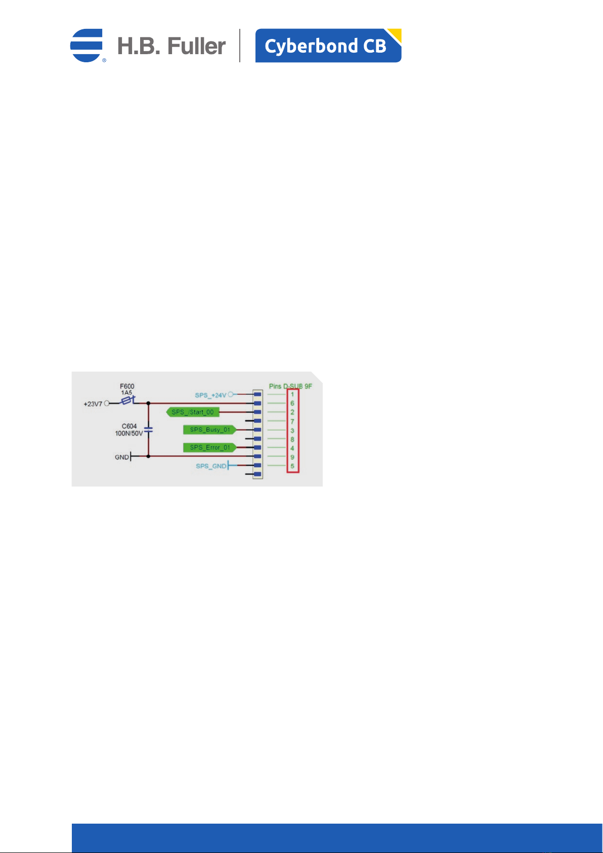
11.5 Digital-Interface DC 24 V
The Digital-Interface is necessary if you want to connect the whole system with a PLC.
The following messages and signals can be used:
Start: in the <man.> mode the signal the the “start-input” determines how long the lamps
are switched on.
In the <auto> mode the signal just determines the start of the prefixed settings.
Another impulse stops the running programme.
Error: shows up when errors occur. The programme will not stop and will continue.
In case you wish to stop the system this has to be done manually or via PLC settings.
Busy: shows if programme is active
If the whole system should be connected with a PLC, potential of the external device has to be distributed
via Pins 1 and 5. Internally signals and voltage are potential-free separated.
In case the system is used without external voltage, the potential of Pins 6 and 9 can be used
as external start button. In this case Pin 1 has to be bridged with 6 and Pin 5 with 9.
Pin 1,5: power supply comes from PLC to control unit LINOP U 500
Pin 2: start impulse from PLC to control unit LINOP U 500 (24 V DC input)
Pin 3: busysignal from control unit LINOP U 500 to PLC (24 V DC exit)
Pin 4: errorsignal from control unit LINOP U500 to PLC (24 V DC exit)
11.6 Equipotential bonding conductor connection (PE)
In order to connect system with external earth wire.

Cyberbond CB
Page 18Cyberbond LINOP U 500 / Operating Instructions
LINOP U 500
Technical data LINOP U 500
Supply voltage external power adapter 100 – 240 V 50 Hz/60 Hz, min. 3 A exit
Supply voltage LINOP U 500 24 V / DC
Safety class 3
Type of protection 31
Current demand 2 W without UV-LED, ca. 60 W with UV-LED
Start signal at Digital Interface equipotential contact or transistor (max. 24 mA)
Measurements 168 x 125 x 278 mm (W x H x B) without flexible arm
Chassis material ABS
Weight ca. 1,550 kg
Working temperature – 25 °C to 60 °C
12 Technical data LINOP U 500

Cyberbond CB
Page 19Cyberbond LINOP U 500 / Operating Instructions
LINOP U 500
LINOP Dosing and Curing Equipment
Dosing & Curing Units
LINOP M 600 10100
LINOP M 1500 10200
LINOP M 2000 10300
LINOP U 500 10500
power supply unit 10190
cord for power supply unit (EU standard) 10191
flexible arm 10192
valve plate (to hold valve M 1500 / M 2000 & Cyberlite) 10193
syringe plate (to hold 30 ml syringe / M 600) 10194
VCA and VAN Valves
LINOP VCA Valve for CA 20100
LINOP VAN Valve for AN 20200
adapters product flow into the valve
product adapter (rectangular) AA 4/6 20194
product adapter (rectangular) AA 4/6 (for UV) 20195
product adapter (rectangular) AA 6/8 20196
product adapter (rectangular) AA 6/8 (for UV) 20197
adapters product flow out of the valve
dosing tip adapter (Fine Thread (in) / Luer Lock (out)) 1/8 20150
UV dosing tip adapter (Fine Thread (in) / Luer Lock (out)) 1/8 20151
adapter as tube connector (Fine Thread (in)) 1/8-2,5 (for 2,5 mm tube) 20152
adapter as tube connector (Fine Thread (in)) 1/8-4,0 (for 4 mm tube) 20154
UV adapter as tube connector (Fine Thread (in)) 1/8-4,0 (for 4 mm tube) 20155
adapter as tube connector (Fine Thread (in)) 1/8-6,0 (for 6 mm tube) 20156
UV adapter as tube connector (Fine Thread (in)) 1/8-6,0 (for 6 mm tube) 20157
EM 24 Valves
EM 24 Valve with plug 30100
EM 24 Valve without plug 30150
EM 24 R Valve with plug 30200
EM 24 R Valve without plug 30250
adapters product flow into and out of the the valve
adapter Fine Thread (in) / Luer Lock male (out) (former A1) 30190
UV adapter Fine Thread (in) / Luer Lock male (out) (former A4) 30191
Impuls Devices
electrical footswitch with plug (FOT) 40100
Hand Pen 40200
Hand Pen electric 40300
adapter tube fixing hand pen for 2,5 mm tube 40392
adapter tube fixing hand pen for 4,0 mm tube 40394
Druckbehälter
PP 505 Pressure Pot with air pressure nipple 50100
empty alarm with plug 50150
adapter for pressure pot lid / 1/4‘‘ for 2,5 product tube 50192
adapter for pressure pot lid / 1/4‘‘ for 4 product tube 50194
adapter for pressure pot lid / 1/4‘‘ for 6 product tube 50196
adapter for pressure pot lid / 1/4‘‘ for 8 product tube 50198
13 LINOP Item Numbers

Cyberbond CB
Page 20Cyberbond LINOP U 500 / Operating Instructions
LINOP U 500
Tubes and Tube Connectors
product tube PTFE, 2,5 mm outside (per meter) 60200
adapter as tube connection / Luer Lock for 2,5 mm tube 60250
product tube PTFE, 4 mm outside (per meter) 60400
adapter as tube connection / Luer Lock for 4 mm tube 60450
UV product tube PTFE, 4 mm outside (per meter) 60401
UV adapter as tube connection / Luer Lock 4 mm tube 60451
product tube PTFE, 6 mm outside (per meter) 60600
adapter tube connection / Luer Lock (former A2) for 6 mm tube 60650
UV product tube PTFE, 6 mm outside (per meter) 60601
UV adapter tube connection / Luer Lock for 6 mm tube 60651
product tube PTFE, 8 mm outside (per meter) 60700
UV product tube PTFE, 8 mm outside (per meter) 60701
blue air supplying tube (per meter) 60800
Syringes for M 600
10 ml syringe black 70110
30 ml syringe black 70130
piston 10 ml syringe UV 70111
piston 30 ml syringe UV 70131
closure cap for 10 and 30 ml syringes) 70141
Adapter for air supply to syringe 10 ml 70115
Adapter for air supply to syringe 30 ml 70135
Reducer from 30 to 10 ml syringe 70200
Cyberlites
Cyberlite 50 S 80260
BoosterPack 13 A 80013
Cable LDV 2 m 80194
Cyberlite 4 S 80200
lens Block Cyberlite 4 S 80250
Splitter 80300
cord 2 m (with straight connectors) 80192
Dosing Tips
Dosing Tips plastic (only DT 1 with Luer Lock)
10 pieces DT „0“
10 pieces DT „0,5“
10 pieces DT „1“
10 pieces DT „0“ UV
Dsing Tips metal, LL
10 pieces DS 1,0“ - 1,37 brown DS 1,0“- 1,37
10 pieces DS 0,5“ - 0,33 orange DS 0,5“- 0,33
10 pieces DS 0,5“ - 0,61 rose DS 0,5“- 0,61
Table of contents


