H. HERMANN EHLERS F010-P User manual

F010-P
FLOWRATE INDICATOR
Signal input flowmeter: pulse, Namur and coil.
Options: Intrinsically Safe.
F-Series - Field mounted indicators for safe and hazardous areas. More info: www.fluidwell.com/fseries
An der Autobahn 45 ♦28876 Oyten ♦Tel. 04207/91 21-0 ♦Fax 04207/91 21 41
Email verkauf@ehlersgmbh.de ♦Home http://www.ehlersgmbh.com/de

HF010PEN_v0403_03 Atex_IECEx_CSA_FM
Page 2
SAFETY INSTRUCTIONS
Any responsibility is lapsed if the instructions and procedures as described in this
manual are not followed.
LIFE SUPPORT APPLICATIONS: The F010-P is not designed for use in life support
appliances, devices, or systems where malfunction of the product can reasonably be
expected to result in a personal injury. Customers using or selling these products for use
in such applications do so at their own risk and agree to fully indemnify the manufacturer
and supplier for any damages resulting from such improper use or sale.
Electro static discharge does inflict irreparable damage to electronics! Before installing
or opening the unit, the installer has to discharge himself by touching a well-grounded
object.
This unit must be installed in accordance with the EMC guidelines (Electro Magnetic
Compatibility).
Do connect a proper grounding to the aluminum casing as indicated if the F010-P has
been supplied with the 115-230V AC power-supply type PM. The green / yellow wire
between the back-casing and removable terminal-block may never be removed.
Intrinsically Safe applications: follow the instructions as mentioned in Chapter 5 and
consult “Fluidwell F0..-..-XI - Documentation for Intrinsic Safety”.
DISPOSAL
At the end of its life this product should be disposed of according to local regulations
regarding waste electronic equipment. If a battery is present in this product it should be
disposed of separately. The separate collection and recycling of your waste equipment will
help to conserve natural resources and ensure that it is recycled in a manner that protects
the environment.
SAFETY RULES AND PRECAUTIONARY MEASURES
The manufacturer accepts no responsibility whatsoever if the following safety rules and
precautions instructions and the procedures as described in this manual are not followed.
Modifications of the F010-P implemented without preceding written consent from the
manufacturer, will result in the immediate termination of product liability and warranty period.
Installation, use, maintenance and servicing of this equipment must be carried out by authorized
technicians.
Check the mains voltage and information on the manufacturer's plate before installing the unit.
Check all connections, settings and technical specifications of the various peripheral devices
with the F010-P supplied.
Open the casing only if all leads are free of potential.
Never touch the electronic components (ESD sensitivity).
Never expose the system to heavier conditions than allowed according to the casing
classification (see manufacture's plate and chapter 4.2.).
If the operator detects errors or dangers, or disagrees with the safety precautions taken, then
inform the owner or principal responsible.
The local labor and safety laws and regulations must be adhered to.

HF010PEN_v0403_03 Atex_IECEx_CSA_FM
Page 3
ABOUT THE OPERATION MANUAL
This operation manual is divided into two main sections:
The daily use of the unit is described in chapter 2 "Operation". These instructions are meant for
users.
The following chapters and appendices are exclusively meant for electricians/technicians. These
provide a detailed description of all software settings and hardware installation guidance.
This operation manual describes the standard unit as well as most of the options available. For
additional information, please contact your supplier.
A hazardous situation may occur if the F010-P is not used for the purpose it was designed for
or is used incorrectly. Please carefully note the information in this operating manual
indicated by the pictograms:
A "warning" indicates actions or procedures which, if not performed correctly, may lead to
personal injury, a safety hazard or damage of the F010-P or connected instruments.
A "caution" indicates actions or procedures which, if not performed correctly, may lead to
personal injury or incorrect functioning of the F010-P or connected instruments.
A "note" indicates actions or procedures which, if not performed correctly, may indirectly
affect operation or may lead to an instrument response which is not planned.
Hardware version : FB03.03.xx
Software version : 03.02.xx
Manual : HF010PEN_v0403_03 Atex_IECEx_CSA_FM
© Copyright 2012 : Fluidwell bv - The Netherlands.
Information in this manual is subject to change without prior notice. The
manufacturer is not responsible for mistakes in this material or for incidental
damage caused as a direct or indirect result of the delivery, performance or
use of this material.
© All rights reserved. No parts of this publication may be reproduced or used
in any form or by any means without written permission of your supplier.

HF010PEN_v0403_03 Atex_IECEx_CSA_FM
Page 4
CONTENTS MANUAL
Safety instructions ...........................................................................................................................................2
Disposal ....................................................................................................................................................2
Safety rules and precautionary measures.......................................................................................................2
About the operation manual ............................................................................................................................3
Contents manual..............................................................................................................................................4
1.Introduction .................................................................................................................................5
1.1.System description of the F010-P..........................................................................................5
2.Operational..................................................................................................................................6
2.1.General ..................................................................................................................................6
2.2.Control panel..........................................................................................................................6
2.3.Operator information and functions .......................................................................................7
3.Configuration...............................................................................................................................8
3.1.Introduction ............................................................................................................................8
3.2.Programming SETUP-level....................................................................................................8
3.2.1.General ..................................................................................................................................8
3.2.2.Overview functions SETUP level.........................................................................................11
3.2.3.Explanation of SETUP-functions..........................................................................................12
1 - Flowrate.....................................................................................................................12
2 - Display.......................................................................................................................13
3 - Power management ..................................................................................................13
4 - Flowmeter..................................................................................................................14
5 - Others........................................................................................................................14
4.Installation.................................................................................................................................15
4.1.General directions................................................................................................................15
4.2.Installation / surrounding conditions ....................................................................................15
4.3.Dimensions- Enclosure........................................................................................................16
4.4.Installing the hardware.........................................................................................................18
4.4.1.Introduction ..........................................................................................................................18
4.4.2.Terminal connectors with power supply - type : PB / PD / PL / PX .....................................19
4.4.3.Terminal connectors with power supply - type : PF / PM ....................................................23
5.Intrinsically safe applications.....................................................................................................27
5.1.General information and instructions:..................................................................................27
5.2.Terminal connectors Intrinsically Safe applications:............................................................28
5.3.Configuration examples Intrinsically Safe applications:.......................................................29
5.4.Battery replacement instructions..........................................................................................31
6.Maintenance..............................................................................................................................32
6.1.General directions................................................................................................................32
6.2.Repair...................................................................................................................................32
Appendix A:Technical specification..............................................................................................................33
Appendix B:Problem solving.........................................................................................................................36
Index of this manual.......................................................................................................................................37
List of figures in this manual..........................................................................................................................38
Notes ..................................................................................................................................................39

HF010PEN_v0403_03 Atex_IECEx_CSA_FM
Page 5
1. INTRODUCTION
1.1. SYSTEM DESCRIPTION OF THE F010-P
Functions and features
The flowrate indicator model F010-P is a microprocessor driven instrument designed to display the
actual flowrate.
This product has been designed with a focus on:
ultra-low power consumption to allow long-life battery powered applications (type PB / PC),
intrinsic safety for use in hazardous applications (type XI),
several mounting possibilities with GRP or aluminum enclosures for industrial surroundings,
ability to process all types of flowmeter signals,
Flowmeter input
This manual describes the unit with a pulse type input from the flowmeter "-P version". Other
versions are available to process (0)4-20mA or 0-10V flowmeter signals.
One flowmeter with a passive or active pulse, Namur or coil signal output can be connected to the
F010-P. To power the sensor, several options are available.
Fig. 1: Typical application for the F010-P.
Configuration of the unit
The F010-P has been designed to be implemented in many types of applications. For that reason, a
SETUP-level is available to configure your F010-P according to your specific requirements.
It includes several important features, such as K-Factor, measurement units, signal selection etc. All
setting are stored in EEPROM memory and will not be lost in the event of power failure. To extend
the battery-life time, please use of the power-management functions as described in chapter 3.2.3.
Display information
The unit has a very large transflective LCD with all kinds of symbols and digits to display measuring
units, status information and key-word messages.
Flowrate values are displayed with the large 26mm (1”) digits while the smaller 8mm (0.31”) digits
will display the measuring and time unit.
The Piegraph is percentage-wise related to the span.
Options
The following options are available: intrinsic safety, power- and sensor-supply options, panel-mount,
wall-mount and weather-proof enclosures, flame proof enclosure and LED backlight.
Overview typical application F010

HF010PEN_v0403_03 Atex_IECEx_CSA_FM
Page 6
2. OPERATIONAL
2.1. GENERAL
The F010-P may only be operated by personnel who are authorized and trained by the
operator of the facility. All instructions in this manual are to be observed.
Take careful notice of the " Safety rules, instructions and precautionary measures " in the
front of this manual.
This chapter describes the daily use of the F010-P. This instruction is meant for users / operators.
2.2. CONTROL PANEL
The following keys are available:
Fig. 2: Control Panel.
Functions of the keys
This key is used to program and save new values or settings.
It is also used to gain access to SETUP-level; please read chapter 3.
The arrow-key is used to increase a value at SETUP level
after PROG has been pressed
or to configure the unit; please read chapter 3.
The arrow-key is used to select a digit at SETUP level after PROG has been
pressed or to configure the unit; please read chapter 3.

HF010PEN_v0403_03 Atex_IECEx_CSA_FM
Page 7
2.3. OPERATOR INFORMATION AND FUNCTIONS
In general, the F010-P will always function at Operator level. The information displayed is dependant
upon the SETUP-settings. All pulses generated by the connected flowmeter are measured by the
F010-P in the background, whichever screen refresh rate setting is chosen. After pressing a key, the
display will be updated very quickly during a 30 second period, after which it will slow-down again.
Fig. 3: Example of display information during process.
For the Operator, the following functions are available:
Display flowrate
This is the main display information of the F010-P. After selecting any other information, it will
always return to this main display automatically.
When "-------" is shown, then the flowrate value is too high to be displayed.
Piegraph indication
This 10 segment Piegraph gives a quick impression about the actual value in relation to its
measuring range in a scale of 0-100%.
As soon as the input value is 5% above the calibrated measurement range, the piegraph
starts flashing.
Low-battery alarm
When the battery voltage drops, it must be replaced. At first "low-battery" will flash, but as
soon as it is displayed continuously, the battery MUST be replaced shortly after!
Only original batteries supplied by the manufacturer may be used, else the guarantee and
liability will be terminated. The remaining lifetime after the first moment of indication is
generally several days up to some weeks.
Fig. 4: Example of low-battery alarm.
Range error
As soon as the input value is 5% outside the calibrated measurement range, the piegraph
starts flashing. Meanwhile, LO RANGE or HI RANGE will be displayed.
Alarm 01-03
When "alarm" is displayed, please consult Appendix B: problem solving.

HF010PEN_v0403_03 Atex_IECEx_CSA_FM
Page 8
3. CONFIGURATION
3.1. INTRODUCTION
This and the following chapters are exclusively meant for electricians and non-operators. In these,
an extensive description of all software settings and hardware connections are provided.
Mounting, electrical installation, start-up and maintenance of the instrument may only be
carried out by trained personnel authorized by the operator of the facility. Personnel must
read and understand this Operating Manual before carrying out its instructions.
The F010-P may only be operated by personnel who are authorized and trained by the
operator of the facility. All instructions in this manual are to be observed.
Ensure that the measuring system is correctly wired up according to the wiring diagrams. The
housing may only be opened by trained personnel.
Take careful notice of the " Safety rules, instructions and precautionary measures " in the
front of this manual.
3.2. PROGRAMMING SETUP-LEVEL
3.2.1. GENERAL
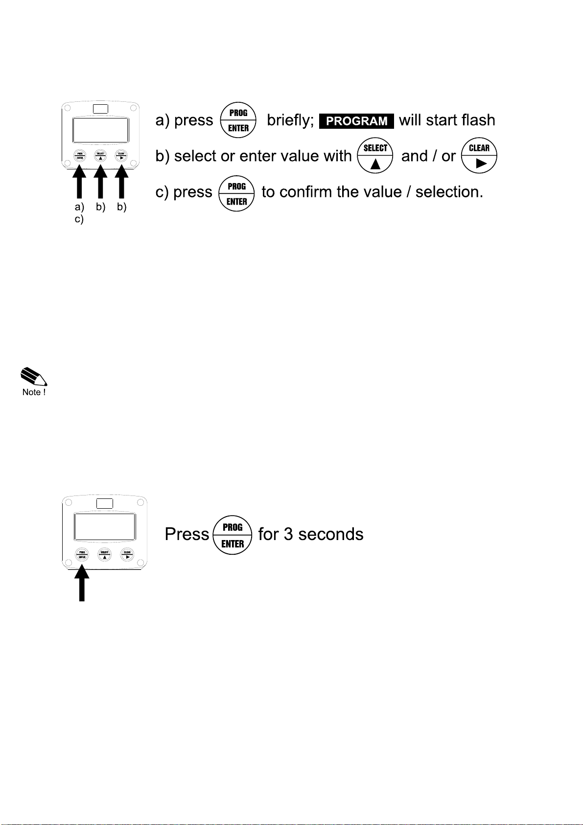
Configuration of the F010-P is done at SETUP-level. SETUP-level is reached by pressing the
PROG/ENTER key for 7 seconds; at which time, both arrows will be displayed. In order to return
to the operator level, PROG will have to be pressed for three seconds. Alternatively, if no keys are
pressed for 2 minutes, the unit will exit SETUP automatically.
SETUP can be reached at all times while the F010-P remains fully operational.
Note: A pass code may be required to enter SETUP. Without this pass code access to SETUP is
denied.
To enter SETUP-level:

HF010PEN_v0403_03 Atex_IECEx_CSA_FM
Page 9
Matrix structure SETUP-level:
SCROLLING THROUGH SETUP-LEVEL
Selection of function-group and function:
SETUP is divided into several function groups and functions.
Each function has a unique number, which is displayed below the word "SETUP" at the bottom of
the display. The number is a combination of two figures. The first figure indicates the function-group
and the second figure the sub-function. Additionally, each function is expressed with a keyword.
After selecting a sub-function, the next main function is selected by scrolling through all "active" sub-
functions (e.g. 1, 11, 12, 13, 14, 1, 2, 3, 31 etc.). The “CLEAR” button can be used
to jump a step back if you missed the desired function.
HF010PEN_v0403_03 Atex_IECEx_CSA_FM
Page 10
To change or select a value:
To change a value, use to select the digits and to increase that value.
If the new value is invalid, the increase signor decrease-signwill be displayed while you are
programming.
To select a setting, is used to select in one direction and can be used to select in the other
direction.
When data is altered but ENTER is not pressed, then the alteration can still be cancelled by waiting
for 20 seconds or by pressing ENTER for three seconds: the PROG-procedure will be left
automatically and the former value reinstated.
Note: alterations will only be set after ENTER has been pressed!
To return to OPERATOR-level:
In order to return to the operator level, PROG will have to be pressed for three seconds. Also, when
no keys are pressed for 2 minutes, SETUP will be left automatically.

HF010PEN_v0403_03 Atex_IECEx_CSA_FM
Page 11
3.2.2. OVERVIEW FUNCTIONS SETUP LEVEL
SETUP FUNCTIONS AND VARIABLES
1 FLOWRATE
11 UNIT mL - L - m3 - mg - g - kg - ton - GAL - bbl - lb - cf - REV - no unit
- scf - Nm3 - NL - P
12 TIME UNIT sec - min - hour - day
13 DECIMALS 0 - 1 - 2 - 3 - 4 - 5 (Ref: displayed value)
14 K-FACTOR 0.00001 - 199,999
15 DECIMALS K-FACTOR 0 - 5
16 CALCULATION per 1 - 255 pulses
17 CUT-OFF 0.1 - 999.9 seconds
18 GRAPH MAX 0.00000 - 199,999 unit/time unit
2 DISPLAY
21 BARGRAPH off - on
22 BACKLIGHT (optional) off - green - amber
23 BL. BRIGHTNESS 1 - 5
3 POWER MANAGEMENT
31 LCD UPDATE fast - 1 sec - 3 sec - 15 sec - off
32 BATTERY MODE operational - shelf
4 FLOWMETER
41 SIGNAL npn - npn_lp - reed - reed_lp - pnp - pnp_lp - namur - coil_hi -
coil_lo - active
5 OTHERS
51 TYPE / MODEL F010-P
52 SOFTWARE VERSION 03.xx.xx
53 SERIAL NO. xxxxxxx
54 PASS CODE 0000 - 9999
55 TAGNUMBER 0000000 - 9999999

HF010PEN_v0403_03 Atex_IECEx_CSA_FM
Page 12
3.2.3. EXPLANATION OF SETUP-FUNCTIONS
1 - FLOWRATE
MEASUREMENT UNIT
11 SETUP - 11 determines the measurement unit for flowrate.
The following units can be selected:
mL - L - m3 - mg - g - kg - ton - GAL - bbl - lb - cf - REV - no unit -
scf - Nm3 - NL - P.
Alteration of the measurement unit will have consequences for operator
and SETUP-level values. Please note that the K-Factor has to be adapted
as well; the calculation is not done automatically.
TIME UNIT
12 The flowrate can be calculated per second (SEC), minute (MIN), hour
(HR) or day (DAY).
DECIMALS
13 This setting determines for flowrate the number of digits following the
decimal point. The following can be selected:
00000 - 1111.1 - 222.22 - 333.333 - 4.4444 - .55555
K-FACTOR
14 With the K-factor, the flowmeter pulse signal is converted to a flowrate.
The K-factor is based on the number of pulses generated by the
flowmeter per selected measurement unit (SETUP 11), for example per
liter. The more accurate the K-factor, the more accurate the functioning of
the system will be.
Example 1: Calculating the K-factor.
Let us assume that the flowmeter generates 2.4813 pulses per
liter and the selected unit is "cubic meters / m3". A cubic meter
consists of 1000 parts of one liter which implies 2,481.3 pulses
per m3. So, the K-factor is 2,481.3. Enter for SETUP - 14:
"24813" and for SETUP - 15 - decimals K-factor "1".
Example 2: Calculating the K-factor.
Let us assume that the flowmeter generates 6.5231 pulses per
gallon and the selected measurement unit is gallons. So, the K-
Factor is 6.5231. Enter for SETUP - 14: "65231" and for
SETUP - 15 decimals K-factor "4".
DECIMALS K-FACTOR
15 This setting determines the number of decimals for the K-factor
(SETUP 14). The following can be selected:
0 - 1 - 2 - 3 - 4 - 5
Please note that this SETUP - influences the accuracy of the K-factor
indirectly. This setting has NO influence on the displayed number of digits
for "flowrate" (SETUP 13)!
CALCULATION
16 The flowrate is calculated by measuring the time between a number of
pulses, for example 10 pulses. The more pulses the more accurate the
flowrate will be. The maximum value is 255 pulses.
Note: the lower the number of pulses, the higher the power consumption
of the unit will be (important for battery powered applications).
Note: for low frequency applications (below 10Hz): do not program more
than 10 pulses else the update time will be very slow.
Note: for high frequency application (above 1kHz) do program a value of
100 or more pulses.
CUT-OFF TIME
17 With this setting, you determine a minimum flow requirement thresh-hold,
if during this time less than XXX-pulses (SETUP 26) are generated, the
flowrate will be displayed as zero.
The cut-off time has to be entered in seconds - maximum time is 999.9
seconds.
GRAPH. MAX.
18 The piegraph gives the Operator an indication of the flowmeter output
value in relation to its measuring range. Enter with this setting, the
maximum flowrate at which value the piegraph will indicate 100%.

HF010PEN_v0403_03 Atex_IECEx_CSA_FM
Page 13
2 - DISPLAY
BARGRAPH
21 The bargraph (piegraph) displayed at operator level is percentage-wise
related to the input signal: minimum signal is 0% and maximum signal is
100% (setup 18).
With this function, the bargraph can be enabled / disabled.
Following selections are available:
OFF - ON
The functions below will only effect the optional LED-backlight.
BACKLIGHT
(OPTION)
22
If a LED backlight has been supplied, the color can be selected.
Following selections are available:
OFF - GREEN - AMBER
BRIGHTNESS
(OPTION)
23
The density of the backlight can be set in following range:
1-5
One is minimum and five is maximum brightness.
3 - POWER MANAGEMENT
When used with the internal battery option, the user can expect reliable measurement over a long
period of time. The F010-P has several smart power management functions to extend the battery life
time significantly. Two of these functions can be set:
LCD NEW
31 The calculation of the display-information influences the power
consumption significantly. When the application does not require a fast
display update, it is strongly advised to select a slow refresh rate.
Please understand that NO information will be lost; the input signal will be
processed and the output signal will be generated in the normal way.
The following can be selected:
Fast - 1 sec - 3 sec - 15 sec - off.
Example battery life-time:
life-time with a coil pick-up, 1kHz. pulses and FAST update: about 2 years.
life-time with a coil pick-up, 1kHz. pulses and 1sec update: about 5 years.
Note: after a button has been pressed by the operator - the display
refresh rate will always switch to FAST for 30 seconds. When "OFF" is
selected, the display will be switched off after 30 seconds and will be
switched on as soon as a button has been pressed.
BATTERY-MODE
32 The unit has two modes: operational or shelf.
After "shelf" has been selected, the unit can be stored for several years; it
will not process the sensor signal; the display is switched off but all
settings are stored. In this mode, power consumption is extremely low.
To wake up the unit again, press the SELECT-key twice.

HF010PEN_v0403_03 Atex_IECEx_CSA_FM
Page 14
4 - FLOWMETER
SIGNAL
41 The F010-P is able to handle several types of input signal. The type of
flowmeter pickup / signal is selected with SETUP 41.
Read also par. 4.4.2. or 4.4.3 - flowmeter input terminals.
TYPE OF SIGNAL EXPLANATION RESISTANCE FREQ./MV
REMARK
NPN NPN input 100kOhm
pull-up 6 kHz. (open collector)
NPN - LP NPN input
with low pass filter 100kOhm
pull-up 1.2 kHz. (open collector)
less sensitive
REED Reed-switch input 1mOhm
pull-up 600 Hz.
REED - LP Reed-switch input
with low pass filter 1mOhm
pull-up 120 Hz. Less sensitive
PNP PNP input 47kOhm
pull-down 6 kHz.
PNP - LP PNP input
with low pass filter 100kOhm
pull-down 1.2 kHz. Less sensitive
NAMUR Namur input 820 Ohm
pull-down 4 kHz. External power
required
COIL HI High sensitive coil input - 20mV
p.t.p. Sensitive for
disturbance!
COIL LO Low sensitive coil input - 90mV
p.t.p. Normal sensitivity
ACTIVE Active pulse input
detection level 1.2V DC 47kOhm 10KHz.
External power
required
5 - OTHERS
TYPE OF MODEL
51 For support and maintenance it is important to have information about the
characteristics of the F010-P.
Your supplier will ask for this information in the case of a serious
breakdown or to assess the suitability of your model for upgrade
considerations.
VERSION SOFTWARE
52 For support and maintenance it is important to have information about the
characteristics of the F010-P.
Your supplier will ask for this information in the case of a serious
breakdown or to assess the suitability of your model for upgrade
considerations.
SERIAL NUMBER
53 For support and maintenance it is important to have information about the
characteristics of the F010-P.
Your supplier will ask for this information in the case of a serious
breakdown or to assess the suitability of your model for upgrade
considerations.
PASS CODE
54 All SETUP-values can be pass code protected.
This protection is disabled with value 0000 (zero).
Up to and including 4 digits can be programmed, for example 1234.
TAGNUMBER
55 For identification of the unit and communication purposes, a unique tag
number of maximum 7 digits can be entered.

HF010PEN_v0403_03 Atex_IECEx_CSA_FM
Page 15
4. INSTALLATION
4.1. GENERAL DIRECTIONS
Mounting, electrical installation, start-up and maintenance of this instrument may only be
carried out by trained personnel authorized by the operator of the facility. Personnel must
read and understand this Operating Manual before carrying out its instructions.
The F010-P may only be operated by personnel who are authorized and trained by the
operator of the facility. All instructions in this manual are to be observed.
Ensure that the measuring system is correctly wired up according to the wiring diagrams.
Protection against accidental contact is no longer assured when the housing cover is
removed or the panel cabinet has been opened (danger from electrical shock). The housing
may only be opened by trained personnel.
Take careful notice of the " Safety rules, instructions and precautionary measures " at the
front of this manual.
4.2. INSTALLATION / SURROUNDING CONDITIONS
Take the relevant IP classification of the casing into account (see manufactures plate). Even an IP67
(NEMA 4X) casing should NEVER be exposed to strongly varying (weather) conditions.
When panel-mounted, the unit is IP65 (NEMA 4)!
When used in very cold surroundings or varying climatic conditions, take the necessary precautions
against moisture by placing a dry sachet of silica gel, for example, inside the instrument case.
Mount the F010-P on a solid structure to avoid vibrations.

HF010PEN_v0403_03 Atex_IECEx_CSA_FM
Page 16
4.3. DIMENSIONS- ENCLOSURE
Aluminum enclosures:
75 mm (2.95")
130 mm (5.12") 112 mm (4.40")
60 mm (2.36")
120 mm (4.72")
M20 x 1,5
PG9 PG9
30mm 30mm
22,5mm
M20 x 1,5
M16 x 1,5 M16 x 1,5
30mm 30mm
22,50mm
M20 x 1,5
22,5mm
M20 x 1,5 M20 x 1,5
25mm 25mm
22,5mm
1/2"NPT
0.9"
3x 1/2"NPT
0.12" 0.12"
0.9"
HA
HM
HN
HO
HP
HT
HU
6 x M12
12mm 12mm
24mm24mm 36mm
36mm
14mm 17mm
115 mm (4.53”)
98 mm (3.86”)
HB
29.1 mm (1.15”)
31 mm
(1.22”)
HZ
4x M20 x 1,5
15 15
15
HV
2323
16
mm
Fig. 5: Dimensions Aluminum enclosures.

HF010PEN_v0403_03 Atex_IECEx_CSA_FM
Page 17
GRP enclosures:
75 mm (2.95")
130 mm (5.12") 112 mm (4.40")
60 mm (2.36")
120 mm (4.72")
HD
HK
HK back box:
(flat bottom)
HE
HF
HG
HH
D=12mm
12mm12mm
24mm24mm 36mm
36mm
14mm 17mm
22,5mm
30mm 30mm
D=16mm
D=20mm
0.9"
D=22mm (0.866")
22,5mm
25mm 25mm
D=20mm D=20mm
D=16mm
HC
75 mm (2.95") 118 mm (4.65”)
104 mm (4.09”)
HJ
0.9”
0.12” 0.12”
3x D=22mm (0.866”)
115 mm (4.53”)
98 mm (3.86”)
29.1 mm (1.15”)
31 mm
(1.22”)
Fig. 6: Dimensions GRP enclosures.

HF010PEN_v0403_03 Atex_IECEx_CSA_FM
Page 18
4.4. INSTALLING THE HARDWARE
4.4.1. INTRODUCTION
Electro static discharge does inflict irreparable damage to electronics! Before installing or
opening the unit, the installer has to discharge himself by touching a well-grounded object.
This unit must be installed in accordance with the EMC guidelines (Electro Magnetic
Compatibility).
Do ground the aluminum casing properly as indicated, if the F010-P has been supplied with
the 115-230V AC power-supply type PM. The green / yellow wire between the back-casing
and removable terminal-block may never be removed.
Fig. 7: Grounding aluminum enclosure with option PM 115-230V AC.
FOR INSTALLATION, PAY EMPHATIC ATTENTION TO:
Separate cable glands with effective IP67 (NEMA4X) seals for all wires.
Unused cable entries: ensure that you fit IP67 (NEMA4X) plugs to maintain rating.
A reliable ground connection for both the sensor, and if applicable, for the metal casing. (above)
An effective screened cable for the input signal, and grounding of it’s screen to the “┴“ terminal
or at the sensor itself, whichever is appropriate to the application.

HF010PEN_v0403_03 Atex_IECEx_CSA_FM
Page 19
4.4.2. TERMINAL CONNECTORS WITH POWER SUPPLY - TYPE : PB / PD / PL / PX
For Intrinsically Safe applications: read chapter 5.
The following terminal connectors are available:
Fig. 8: Overview of terminal connectors F010-P-(PB / PD / PX) and options.
SENSOR SUPPLY
Type PB / PD / PX - terminal 3: sensor supply 1.2V, 3.2V:
Terminal 3 provides a limited supply voltage of 3.2 V DC (coil signals 1.2V) for the signal output of
the flowmeter.
Note: This voltage MAY NOT be used to power the flowmeters electronics, converters etc, as it will
not provide adequate sustained power ! All energy used by the flowmeters pick-up will directly
influence the battery life-time (type PB). It is strongly advised to use a "zero power" pickup such as a
coil or reed-switch when operating without external power. It is possible to use some low power NPN
or PNP output signals, but the battery life time will be significantly reduced (consult your distributor).
Type PD - terminal 6: sensor supply 8.2V:
With this option, a basic but real sensor supply of max. [email protected] is available to power e.g. a
Namur sensor.
5
POWER SUPPLY
UNIT
TYPE: PD/ PX
612
SENSOR SIGNAL
PULSE INPUT
TYPE: P
SIGNAL
3
+ ++
10
POWER SUPPLY
BACKLIGHT
OPTION: ZB
+
SENSOR
SUPPLY
TYPE: PD
49

HF010PEN_v0403_03 Atex_IECEx_CSA_FM
Page 20
REMARKS: TERMINAL CONNECTORS:
Terminals 1-3; Flowmeter input:
Three basic types of flowmeter signals can be connected to the unit: pulse, active pulse or coil. The
screen of the signal wire must be connected to the common ground terminal
The input signal type has to be selected with the correct SETUP-function (read par. 3.2.3.)
Coil-signal:
The F010-P is suitable for use with flowmeters which have a coil output signal.
Two sensitivity levels can be selected with the SETUP-function:
COIL LO: sensitivity from about 90mVp-p.
COIL HI: sensitivity from about 20mVp-p.
Type ZF (option): offers for setting COIL HI : sensitivity from about 10mVp-p.
Type ZG (option): offers for setting COIL HI : sensitivity from about 5mVp-p.
Pulse-signal NPN / NPN-LP:
The F010-P is suitable for use with flowmeters which have a NPN output signal. For reliable pulse
detection, the pulse amplitude has to go below 1.2V. Signal setting NPN-LP employs a low-pass
signal noise filter, which limits the maximum input frequency - read par. 3.2.3.
INTERNAL EXTERNAL
Coil signal input
3
2
COIL
Common ground unit
COIL
1
GND
Input
sensitivity
selectable:
coil high / low
+
V ref.
1.2V DC
shielding
INTERNAL EXTERNAL
NPN signal input
2
Common ground unit
SIGNAL
1
GND
shielding NPN
+ 3.2V DC
100K
low-pass filter
selection NPN-LP
Table of contents
Other H. HERMANN EHLERS Measuring Instrument manuals


Popular Measuring Instrument manuals by other brands

Synthesis Technology
Synthesis Technology E370 Quad Morphing VCO manual

AMAZON COMMERCIAL
AMAZON COMMERCIAL B07VX43ZKN manual

ROOTECH
ROOTECH ACCURA 3500 user guide

York
York 343050 operating instructions

Bushnell
Bushnell TOUR V4 SHIFT manual

PCB Piezotronics
PCB Piezotronics J353B33 Installation and operating manual


Campbell
Campbell CS650 product manual

Dewetron
Dewetron TRION Series Technical reference manual

Logitech Electronics
Logitech Electronics 2000 MKII Series user guide
Icon Process Controls
Icon Process Controls truflo TK Series manual

Ocean Insight
Ocean Insight OCEAN SR2 Installation and operation manual

Ecolab
Ecolab Lub-O-Mat 2.5 operating instructions