East Tester ET1090 User manual

ET1090 Benchtop digital bridge.

Contents
1 Installation........................................................................................................................................ 1
2 Description....................................................................................................................................... 1
2.1 General Technical Specifications..........................................................................................3
3 Quick Reference............................................................................................................................... 4
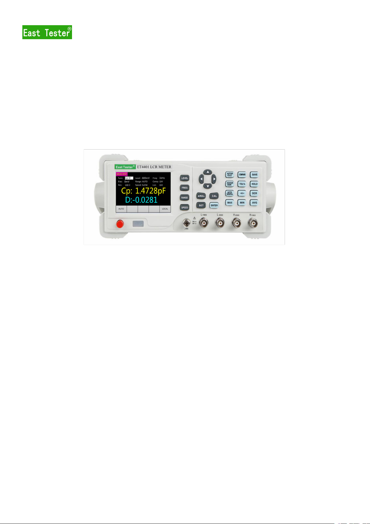
3.1 Front Panel............................................................................................................................ 4
3.2 Introduction of Keys..............................................................................................................4
3.2.1 Power On/Off Key..................................................................................................... 4
3.2.2 Direction Key............................................................................................................. 5
3.2.3 Basic Function Keys.................................................................................................. 5
3.3 Introduction of Rear Panel.................................................................................................... 5
3.4 User Interface........................................................................................................................ 6
3.4.1 Interface of Measurement Display.............................................................................7
3.4.2 Interface of Measurement Setting..............................................................................7
3.4.3 Interface of List Scanning.......................................................................................... 7
3.4.4 Interface of System Setting........................................................................................ 7
4 Basic Function Operation.................................................................................................................7
4.1 Startup & Shutdown.............................................................................................................. 7
4.2 Parameter Selection...............................................................................................................8
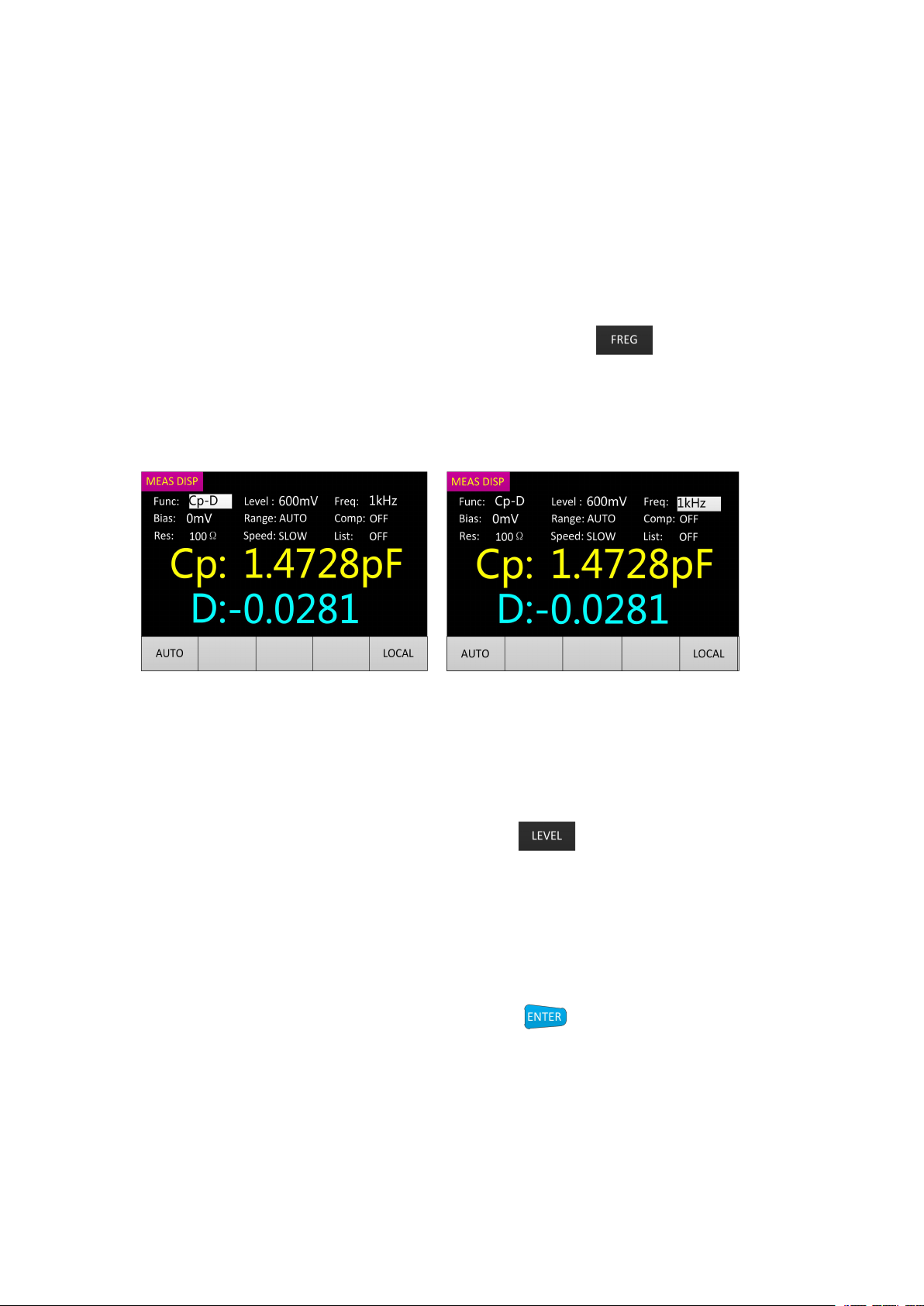
4.2.1 Frequency Selection................................................................................................... 8
4.2.2 Level Selection...........................................................................................................8
4.2.3 Offset Selection.......................................................................................................... 8
4.2.4 Range Selection..........................................................................................................9
4.2.5 Output Impedance Selection...................................................................................... 9
4.2.6 Measurement Display Speed Selection......................................................................9
4.2.7 Main Parameter Selection........................................................................................ 10
4.2.8 Secondary Parameter Selection................................................................................10
4.2.9 Equivalent Mode Selection...................................................................................... 10
4.2.10 Comparator Setting................................................................................................ 10
4.2.11 List Scanning Function...........................................................................................12
4.2.12 DCR MODE...........................................................................................................13
4.2.13 Electrolytic Capacitor Mode.................................................................................. 13
4.2.14 Relative Function................................................................................................... 13
4.2.15 Data Retention Function........................................................................................ 13
4.2.16 Data Recording Function (Maximum Value, Minimum Value, Average Value)...14
4.2.17 Correction Function............................................................................................... 14
4.2.18 Backlight Brightness Setting..................................................................................16
4.2.19 Power-on Parameter Setting...................................................................................16
4.2.20 Buzzer Switch Setting............................................................................................16
5 Basic Performance Indicators.........................................................................................................16
5.1 Measurement Parameter......................................................................................................17
5.2 Equivalent Mode................................................................................................................. 17
5.3 Basic Accuracy.................................................................................................................... 17
5.4 DCR MEASUREMENT ACCURACY.............................................................................. 19
5.5 Test Signal Frequency......................................................................................................... 19
5.6 Test Signal Level................................................................................................................. 19
5.7 Output Impedance............................................................................................................... 20
5.8 Measurement Display Range.............................................................................................. 20
6 External Interface Instructions....................................................................................................... 20
6.1 USB INTERFACE.............................................................................................................. 20
6.2 RS232 INTERFACE........................................................................................................... 20
7 SCPI COMMAND REFERENCE................................................................................................. 20
8 Precautions and Warranty...............................................................................................................21

1
1 Installation
This chapter describes some checks that must be made when you receive the instrument and
the conditions that you must learn and be equipped with before installing the instrument.
1.1 Out of Box Check
Thank you for purchasing and using our products. Before using this instrument, please
confirm the contents of the last chapter "Warranty". In case of any non-conformity, please contact
us as soon as possible to safeguard your interests. Make sure that the following items are attached
to the bridge, where the optional accessories are included with the product only when ordered. If
any items are missing, please contact your nearest sales office.
Standard Accessories:
●Four-terminal-pair Kelvin test cable (35A51).
● Three-core power cord (30A51).
● One User Manual.
Optional accessories:
●RS232 serial cable / USB data cable.
●Handle cable.
●Four-terminal-pair Kelvin test fixture (including
short block)
●SMD component test fixture (including short
block)
1.2 Power connection
(1) Power supply voltage range: 220V AC ± 10%, or 110V AC ± 10%.
(2) Power supply frequency range: 45-65Hz.
(3) Phase line L, zero line N, and ground line E of power input shall be the same as those of the
power plug of this instrument.
(4) The instrument has been carefully designed to reduce the clutter interference caused by the
input at the AC power supply terminal. However, it shall be used in a low noise environment. If
such is not the case, please install the power supply filter.
WARNING: In order to prevent leakage from causing damage to the instrument or person, the user
must ensure that the ground line of the power supply is reliably connected to the earth.
1.3 Fuses
The instrument has been provided with fuses in delivery; the user shall use the fuses provided by
the company.
1.4 Ambient Environment
(1) Please do not use it in the place subject to dust, vibration, direct sunlight and corrosive
gas.
(2) The normal working temperature of this instrument is 0 ℃~ 40 ℃, and working humidity
is from 15% to 85%; Therefore please use the instrument in this condition as far as possible to
ensure the measurement accuracy.
(3) The instrument has been carefully designed to reduce the clutter interference caused by
the input at the AC power supply terminal. If such is not the case, please install the power supply
filter.
(4) If the instrument is not to be used for a long time, please put it in the original box or
similar box and store it in the ventilated room with temperature of 0 ℃~ 40 ℃and relative
humidity of not more than 85% RH; The air in the room shall not contain harmful impurities

2
corrosive to measuring instrument, and direct sunlight shall be avoided.
(5) The instrument, especially the test leads connected to the DUT, shall be kept away from
the strong electromagnetic field to avoid interference to the measurement.
1.5 Test Fixture Used
Please use the test fixture or test cable provided by our company; the test fixture or test cable
made by the user or other companies may lead to incorrect measurement results. The test fixture or
test of the instrument cable shall be kept clean and the pins of the tested device shall be kept clean
to ensure that the device under test is in good contact with the fixture.
The test fixture or test cable shall be connected to such four test terminals as Hforce, Hsense,
Lsense and Lforce on the Front Panel of the instrument. For the device under test with a shielded
enclosure, the shielding layer can be connected to the ground line of the instrument.
NOTE: When there is no Installation of test fixture or test cable, the instrument will display
an unstable measurement result.
1.6 Warm-up and Continuous Working Hours
(1) In order to ensure accurate measurement of the instrument, the warm-up time shall be no less
than 30 minutes after the instrument is turned on; the continuous working hours shall be less than
16 hours.
(2) Please do not switch the instrument frequently, which, otherwise, will cause the confusion of
internal data.
1.7 Other Characteristics of the Instrument
(1) Power consumption: less than 20W.
(2) Dimensions: 265mm * 105mm * 305mm (W *H*L).
2 Description
ET44 series desktop bridge incorporates 3.5-inch TFT display, user-friendly interface, and a
variety of measurement parameters into one body. It is convenient for users to carry out remote
control with USB and RS232 and also perform the sorting of components using handle. In
function, it can not only adjust the output frequency and test level, but also record the value of
components in the process of measurement. In the performance parameters, its basic accuracy
reaches 0.2%. This manual will take ET4410 as an example.
● Measurement frequency up to 100kHz
● Test level 100 ~ 2000mV
●Support the measurement of DC
resistance and electrolytic capacitor
●Internal bias voltage output
(1mV-1500mV)
●Automatic identification of component
measurement
●3.5-inch TFT display, 5 and a half bits
display
● Support SCPI communication protocol
● Provide system settings, which can configure
language, buzzer, screen brightness, etc
according to the needs of users.
● Basic accuracy 0.2%
● Manual and automatic range
● Be equipped with open circuit and short
circuit correction
● Comparator has sorting and alarm function
● Provide a variety of test ports

3
●USB, RS232 communication interface,
Handle sorting
● Data recording function (maximum and
minimum values, average value)
Model
ET1090A
ET1090B
ET1090C
Digits
Main parameter: 5 digits; secondary parameter: 5 digits
Measurement
Parameter
Main parameter: L/C/R/Z; secondary parameter: X/D/Q/θ/ESR
Measurement
Range(L)
0.01μH - 9999H
Measurement
Range(C)
0.01pF - 99999μF
Measurement
Range(R)
0.0001Ω - 99.99MΩ
Basic Accuracy
0.2%
Test Frequency
(Hz)
100~10kHz 10 point
100~20kHz 12point
100~100kHz 20 point
Measurement
Display Speed
2 times/second (slow), 4 times/second (medium speed), 8 times/sec (fast)
Internal Bias
0-1500mV adjustable, 1mV stepping
Test Level
100mV、300mV、600mV、1000mV、1500mV、2000mV
Correction
Function
Open circuit correction, short circuit correction
Screening
function
The screening limit can be set from -50% to + 50% with fixed points of
1%, 5%, 10% and 20%
Selection of
comparator
Five gear sorting, third gear qualified, one gear failed, one ancillary gear
Communication
Interface
Standard configuration: USB, RS232 (or 485), Handle interface; Optional:
GPIB, USB Host
Others
Support DCR, electrolytic capacitor measurement mode, adjustable
backlight brightness, optional in English and Chinese

4
2.1 General Technical Specifications
●Power supply voltage: 220V AC ± 10%, or 110V AC ± 10%, 45-65Hz
●Working environment: 0 ~ 40 ℃, relative humidity <80%.
●Storage environment: -10 ~ 50 ℃, relative humidity <80%.
●Dimensions: 265mm * 105mm * 305mm (width * height* depth).
●Mass: 2.3kg.
●Power consumption: <10W
3 Quick Reference
3.1 Front Panel
Figure 3-1 Diagram of Front Panel
SN
Description
1
Power button
2
3.5 inch display.
3
Test clip jack
4
Basic Function Keys。
3.2 Introduction of Keys
3.2.1 Power On/Off Key
Power on/off key: After connected to the power supply, press down to turn on the
instrument, pop up the key to turn off the instrument.
3.2.2 Direction Key
In the interface of measurement display, left and right keys control the cursor movement, and
up and down direction keys select parameters.

5
In the Interface of System Setting, up and down direction keys control the cursor movement,
and left and right direction keys select parameters.
3.2.3 Basic Function Keys
Quickly switch the level of fixed point.
Quickly switch the frequency of fixed point.
Quickly switch the test range.
Quickly switch the test speed.
Quickly switch between normal display and relative display.
Quickly switch between such two interfaces as "measurement display" and "system
setting”.
Press down to enter the open circuit and short circuit calibration modes, press down
again to enter the calibration state; after the calibration is completed, press down again to exit
the calibration mode and return to the normal mode.
Press down to make the measurement condition (bias, comparator setting) enter the
input state and press down again to exit the input state.
Quick switch the main parameter;
Quickly switch Comparator Setting and Interface of Measurement Display;
Quickly save the currently set comparator parameters.(only valid in the interface of
comparator).
Quickly switch secondary parameter.
Quickly set the tolerance value (only valid in the interface of comparator).
Turn on Data Retention Function.
Quickly switch Equivalent Mode.
Quickly switch the mode of electrolytic capacitor.
Quickly switch DCR DC resistance test function.

6
Record the maximum value of the measurement in this period of time.
Record the minimum value of the measurement in this period of time.
Record the average value of the measurement in this period of time.
3.3 Introduction of Rear Panel
Fig.3-2 Rear Panel
SN
Description
1
Power jack: AC 220V / 50Hz power supply input socket.
2
Voltage selector: 110V / 60Hz VAC or 220V / 50Hz VAC.
3
RS232 INTERFACE.
4
USB Device interface.
3.4 User Interface
3.4.1 Interface of Measurement Display
Fig.3-3 Interface of Measurement Display
1. Page title: It is used to identify the displayed page. There are three pages for measurement
display/measurement setting/system setting respectively.
2. Measurement parameter setting
3. Main / secondary parameter display
4. Message column
4.1 Data automation / retention.
4.2 Relative display

7
4.3 MAX / MIN / AVG label display.
4.4 MAX / MIN / AVG value display.
4.5 Local mode/remote mode. Note: In the remote mode, the keyboard cannot be used; after
entering the remote mode, it is required to manually send instructions back to the local mode (the
default starting state of the instrument is the local mode).
3.4.2 Interface of Measurement Setting
Fig.3-4 Interface of Measurement Display
3.4.3 Interface of List Scanning
Fig.3-5 Interface of List Scanning
3.4.4 Interface of System Setting
Fig.3-6 Interface of System Setting
4 Basic Function Operation
4.1 Startup & Shutdown
Connect the power cord, press down the power button, turn on the instrument, enter the

8
measurement interface (default); when the power button pops up, the instrument will be shut
down.
4.2 Parameter Selection
4.2.1 Frequency Selection
Step one: Turn on the instrument to enter the interface of measurement display; the interface
is as shown in Figure 4-1.
The second step: Switch the cursor to the frequency display area by using left and right
direction keys, or switch to the next frequency point by pressing . (Commonly used
frequency list: 100Hz, 120Hz, 200Hz, 400Hz, 800Hz, 1k, 2k, 4k, 8k, 10k, 15k, 20k, 40K, 50K,
80K, 100K)
The third step: Increase or decrease the frequency by pressing the up and down direction keys
(the commonly used frequency list is as shown above). The interface is as shown in Figure 4-2.
Fig.4-1 Fig.4-2
4.2.2 Level Selection
Step one: Turn on the instrument to enter the interface of measurement display; move the
cursor to the level through the left and right direction keys.
The second step: Switch the cursor to the level display area by using left and right direction
keys, or switch to the next test level by directly pressing . (Commonly used test level list:
100 mV, 300 mV, 600 mV, 1 V, 1.5 V, 2 V)
The third step: Increase or decrease the test level by using the up and down direction keys
(the commonly used test levels are as shown above).
4.2.3 Offset Selection
Turn on the instrument to enter the interface of measurement display, move the cursor to the
bias through the left and right direction keys, press the key to enter the level automatic
setting interface with the interface as shown in Fig.4-3.

9
Fig.4-3
The offset value in the display interface is the current offset value (for example, if the offset
value before the selection is 1V, then the level in the interface will be 1000mV). you can select the
digit bit required to be changed through the left and right direction keys; the selected digit will be
displayed in the inverted manner; the value of such digit can be changed through the up and down
direction keys ( the up direction key means + with the value of + 1; the down direction key means
– with the value of - 1;). After the selection is completed, press the button to enter.
4.2.4 Range Selection
Method one:
Turn on the instrument to enter the interface of measurement display, move the cursor to the
measurement range area and switch the range through the up and down direction keys (AUTO,
30Ω, 100Ω, 300Ω, 1kΩ, 3kΩ, 10kΩ, 30kΩ, 100kΩ).
Method two:
Press the key to directly switch to the next range, and the cursor moves to the range
area.
4.2.5 Output Impedance Selection
The internal resistance is the Output Impedance of the test signal source. This instrument
offers two internal resistance options: 30Ω and 100Ω. Enter the Interface of Measurement Display,
move the cursor to the impedance through the left and right direction keys and switch the Output
Impedance (30Ω, 100Ω) through the up and down direction keys. In the default state, Output
Impedance is 100Ω. (Note: For non-current sensitive, especially low-impedance test pieces, 30Ω
source resistance is recommended.)
4.2.6 Measurement Display Speed Selection
Method one:
Turn on the instrument to enter the interface of measurement display, move the cursor to the
measurement range area and switch the speed through the up and down direction keys (fast,
medium speed, slow).
Method two:
Turn on the instrument to enter the interface of measurement display, press the key to

10
directly switch to the next measurement speed (fast, medium speed, slow).
4.2.7 Main Parameter Selection
Turn on the instrument to enter the interface of measurement display, press the key
to switch to the next main parameter (AUTO, R, C, L, Z). When the Main Parameter is selected
AUTO, the function area will be displayed the word "AUTO".
4.2.8 Secondary Parameter Selection
Turn on the instrument to enter the interface of measurement display, press the key
to switch to the next secondary parameter (X, D, Q, θ, ESR).
4.2.9 Equivalent Mode Selection
Press the key to switch to the next equivalent mode (AUTO, SER, and PAL).
4.2.10 Comparator Setting
(1) Nominal value selection
Step one: Turn on the instrument to enter the interface of measurement display, the instrument test
clip shall be placed with the component with the similar desired nominal value.
Step two: Press the key to open the Interface of Measurement Setting. At this time, the
position of the cursor is at the nominal value in default. The nominal value is the value of the
component under test, and the nominal value shall reserve one digit after decimal point, but the
unit shall not be less than the minimum unit (For example, if the measured value of component is
1.0694kΩ, then nominal value shall be 1.1kΩ; for another example, if the measured value of
component is 330.92Ω, then nominal value shall be 330.9Ω).
If at this time the nominal value is not desired one, move the cursor to the nominal position
through the left and right direction keys and press the key to enter the nominal value
modification interface. The interface is as shown in Fig.4-4. Note: Each time entering the Interface
of Measurement Setting, the nominal value will be automatically updated based on the current
measurement.

11
Fig.4-4
(2) Comparator switch
Method one:
In the Interface of Measurement Display, move the cursor to the comparator through the left and
right direction keys , and then turn on / off the comparator through the up and down direction
keys.
Method Two:
In the Comparator Setting interface, move the cursor to the comparator via the up and down
direction keys, and turn on / off the comparator through the left and right direction keys.
(3) Tolerance Selection
Method one:
Step 1: Turn on the instrument to enter the interface of measurement display, press the
key to enter the Interface of Measurement Setting with the interface as shown in Fig.4-5.
Step 2: Use the direction key to move the cursor to the upper and lower limits of the set gear and
press the key to switch to the next tolerance value (1%, 5%, 10%, 20%) as shown in
Fig.4-6
Fig.4-5 Fig.4-6
Method Two:
Step one: the same as method one
Step two: move the cursor to the tolerance through the left and right direction keys, short press the
key to enter the custom tolerance interface (-50.00% ~ +50%, resolution 0.01%). The
setting method can refer to the custom setting of frequency.
(4) Sorting mechanism
P1, P2 and P3 are used to indicate whether the main parameter is qualified or not. If it is not
qualified, then OUT flag will be displayed on the Interface of Measurement Display (in the case of
turning on the comparator); then the sorting is completed. If it is qualified, P1~P3 will be
displayed 1/2/3 in the measurement display, and continue to execute secondary parameter
comparison. If the secondary parameter is set, and the secondary parameter is not in the range, it
will be displayed AUX.
AUX is used to indicate whether the secondary parameter is qualified or not. If the primary
parameter is qualified, then unqualified secondary parameter will be displayed on the AUX
display.

12
If one of the main parameter and secondary parameter of NG is not qualified, it will be
displayed OUT as shown in Fig.4-7
The comparison process is as shown in Fig.4-8:
Fig.4-7 Fig.4-8
Note: If you want to save the currently set tolerance value, press the key to save. After
saving, the data set will not be lost after shutdown.
4.2.11 List Scanning Function
Turn on the instrument to enter the interface of measurement display, move the cursor to the
list switch through the left and right direction keys, and enter Interface of List Scanning by means
of switching the up and down switch Keys as shown in Fig.4-9 and 4-10. The List Scanning
Function can carry out circulated scanning over seven groups of frequencies and compare them
with the nominal values to get the comparison results. The scanning mode is divided into stepping
scanning and sequential scanning. Set the frequency and upper and lower limits, and then open the
scan display, you can get the measured value and comparison results. Comparison result "H":
greater than upper limit, "L": less than lower limit, "I": within the range between them.
Fig.4-9 Fig.4-10
4.2.12 DCR MODE
Press to enter DCR DC resistance measurement mode. The interface is as shown in
Fig.4-11.

13
Fig.4-11
4.2.13 Electrolytic Capacitor Mode
Press to enter Electrolytic Capacitor Mode. The interface is as shown in Fig.4-12.
Fig.4-12
4.2.14 Relative Function
Short press the key to open and take the current value as the reference value,
secondary parameter will display the reference value and Main parameter will display the relative
value; the interface is as shown in Fig.4-13.
Fig.4-13
4.2.15 Data Retention Function
Press the key to open the Data Retention Function; press the key again to
turn off the function. The interface is as shown in Fig.4-14

14
Fig.4-15
4.2.16 Data Recording Function (Maximum Value, Minimum Value, Average
Value)
Press the key/ key / key to toggle the selection to display the
maximum, minimum, and average values. The key pressing cycle is 2 times per cycle. For
example,Press key the first time to display the maximum value, press the second to exit
the record maximum mode. The interface is as shown in Fig.4-16.
Fig.4-16
4.2.17 Correction Function
Correctio
n
Function
Description
Typical Use
Model
Open
circuit
correction
Compensate for the
stray admittance
caused by the test
fixture
High impedance
measurement
Short
circuit
correction
Compensate for the
residual impedance
caused by the test
fixture
Low impedance
measurement
Open/sho
rt circuit
Compensate for the
stray admittance and
Precision measurement
----

15
correction
residual impedance
caused by the test
fixture
Step 1: Press the key to enter the correction interface. The interface is as shown in
Fig.4-17. If you do not want to perform correction, press the Main parameter function
key to exit. In this mode, only the key and the Main parameter function key
are valid. (Open circuit: OPEN, short circuit, SHORT, neither: ERROR). Connect the test
fixture to the gold plated short circuit board (short circuit) or disconnect the outside of the fixture
(open circuit).
Fig.4-17
Step 2: Press the key to carry out open or short circuit correction (automatic
identification of open circuit, short circuit, open circuit OPEN, short circuit SHORT) with the
interface as shown in Fig.4-18 (the number will be added 1 along with the correction progress,).
If the correction is successful, the word "success" is displayed in the position where "Digital" is
displayed. If it fails, "FAIL" will be displayed as shown in Fig.4-19; press the key
again to return to Interface of Measurement Display.
Fig.4-18 Fig.4-19
Step 1: Turn on the instrument to enter the interface of measurement display, and press the
key to enter the Interface of System Setting.
Step 2: Move the cursor to "Brightness Adjustment" through the up and down direction keys,
and switch the backlight brightness (30%, 50%, 70%, 100%) through the left and right direction
keys.

16
4.2.18 Power-on Parameter Setting
Step 1: Turn on the instrument to enter the interface of measurement display, and press the
key to enter the Interface of System Setting。
Step 2: Move the cursor to the "Power-on Setting " via the up and down direction keys, and
then switch the "Power-on Setting " (default value, previous value) through the left and right
direction keys.
4.2.19 Buzzer Switch Setting
Step 1: Turn on the instrument to enter the interface of measurement display, and press the
key to enter the Interface of System Setting.
Step 2: Move the cursor to the "buzzer" via the left and right direction keys, and then switch
the buzzer switch (ON and OFF) through the up and down direction keys.
The selection range for the system setting parameters is as shown in the table below.
System Language
Chinese, English
Brightness Adjustment
30%, 50%, 70%, 100%
Power-on Setting
Default value, previous value
Buzzer
OFF, ON
5 Basic Performance Indicators
5.1 Measurement Parameter
(1) Main parameter: L: inductance; C: capacitance; R: resistance; Z: impedance.
(2) Secondary parameter: X: reactance; D: loss; Q: quality factor; θ: impedance angle ESR: series
equivalent resistance.
(3) Measurement Parameter combination: the combination of main parameter and any secondary
parameter
5.2 Equivalent Mode
SER: series connection; PAR: parallel connection.
The actual inductance, capacitance and resistance are not the ideal pure reactance or
resistance elements, but the complex impedance elements in series or parallel form; this
instrument calculates the required value according to the series or parallel equivalent circuit with
different equivalent circuit obtaining different results. The two equivalent circuits can be
converted through the formula listed in the table Equivalent Circuit Conversion. Q and D are the
same regardless of what equivalent mode.
Series/parallel Circuit Model
The circuit models and formulas of the six series and parallel equivalent circuits are
described below: capacitance, inductance and resistance. The formula contains all the types of first
measurement and second measurement.

17
Capacitance(C) Schematic Diagram of Series Connection Schematic
Diagram of Parallel Connection
Series Connection Formula Parallel Connection Formula
)1( 2
DCpCs
)1( 2
D
Cs
Cp
Inductance (L) Schematic Diagram of Series Connection Schematic
Diagram of Parallel Connection
Series Connection Formula Parallel Connection Formula
)
1
1( 2
Q
Lp
Ls
)
1
1( 2
Q
LsLp
Resistance(R) Schematic Diagram of Series Connection Schematic
Diagram of Parallel Connection
Series Connection Formula Parallel Connection Formula
)1( 2
Q
Rp
Rs
)1( 2
QRsRp
Note: In the component parameters, the subscript s represents the series connection equivalent,
and p represents the parallel connection equivalent. In general, the series equivalent circuit shall
be used for low-value impedance elements (basically high-value capacitance and low-value
inductance); on the contrary, the parallel equivalent circuit shall be used for high-value impedance
elements (basically low-value capacitance and high-value inductance). Meanwhile, it is advisable
to determine the equivalent circuit according to the actual use of the components; for example,
when the capacitor is used for power supply filter, the series equivalent circuit shall be used, while,
when the capacitor is used for LC oscillation circuit, the parallel equivalent circuit shall be used.
5.3 Basic Accuracy
The following data shall be measured under the following conditions:

18
Temperature condition: 23℃±5℃
Humidity condition: ≤65% R.H.
Zero value adjustment : open circuit and short circuit zeroed before the test
Warm-up time:> 30 minutes
Calibration time: 12 months
C: 0.20%*(1+ Cx/Cmax+ Cmin/Cx )(1+Dx)(1+ks+kv+kf);
L: 0.20%*(1+ Lx/Lmax+ Lmin/Lx )(1+1/Qx)(1+ks+kv+kf);
Z: 0.20%*(1+ Zx/Zmax+ Zmin/Zx )(1+ks+kv+kf);
R: 0.20%*(1+ Rx/Rmax+ Rmin/Rx )(1+Qx)(1+ks+kv+kf);
D: 0.20%*(1+ Zx/Zmax+ Zmin/Zx )(1+Dx+Dx*Dx)(1+ks+kv+kf );
Q: 0.20%*(1+ Zx/Zmax+ Zmin/Zx )(Qx+1/Qx )(1+ks+kv+kf );
Wherein
1. L, C, R, Z are relative errors; D, Q, θ are absolute errors
2. Where the subscript is x, it is the measurement of this parameter; where the subscript is max, it
is the maximum value and where the subscript is min, it is the minimum value
3. Ks is the velocity factor, kv is the voltage factor, kf is the frequency factor
The maximum and minimum values of the measurement parameters that affect accuracy
Frequenc
y(Hz)
100
120
200
400
800
1K
2K
4K
8K
10K
Cmax
800
667
400
200
100
80
40
20
10
8
Cmin
1500
1250
750
375
187
150
75
37.5
18.7
15
Lmax
1590
1325
795
397.5
198.8
159
79.5
39.8
19.9
15.9
Lmin
3.2
2.6
1.6
0.8
0.4
0.32
0.16
0..08
0.04
0.032
Z/Rmax
1
Z/Rmin
1.59
Frequenc
y (Hz)
15K
20K
40K
50K
80K
100K
Cmax
5.3
4
2
1.6
1
0.8
Cmin
10
7.5
3.75
3
1.87
1.5
Lmax
10.6
7.95
3.98
3.18
1.99
1.59
Lmin
0.021
0.016
0.008
0.0064
0.004
0.0032
Z/Rmax
1
Z/Rmin
1.59
Wherein: the unit of Cmax is uF; the unit of Cmin is pF; the unit of Lmax is H; the unit of Lmin is
mH; the unit of Zmax / Rmax is MΩ; the unit of Zmin / Rmin is in Ω;
Measurement speed error factor ks:
Measurement speed error factor kf:
Frequency
100~1K
2K~10K
15K
20K
40K
50K
80K
100K
kf
0
0.5
1
2
3
Measurement speed error factor kv:
Level(mV)
100
300
600
1000
1500
2000
kv
10
3
1
0
1
2
Speed Mode
Slow
Medium
Fast
ks
0
1
8
This manual suits for next models
3
Table of contents
Other East Tester Measuring Instrument manuals
Popular Measuring Instrument manuals by other brands

Topcon
Topcon BM-9A instruction manual

R&S
R&S ZNL Series Getting started

Thermo Scientific
Thermo Scientific Orion Star quick start guide

BJE
BJE 007685 Recommended Installation, Maintenance and Inspection Instructions

Keysight Technologies
Keysight Technologies P939 A Series user guide

Dräger
Dräger Pac 3000 instruction manual