H.
Wilson
C
ompany
-
Phone:
800.245.7224
|
Email:
[email protected] |
W
eb:
ww
w
.hwilson.com
APRIL 2011
6
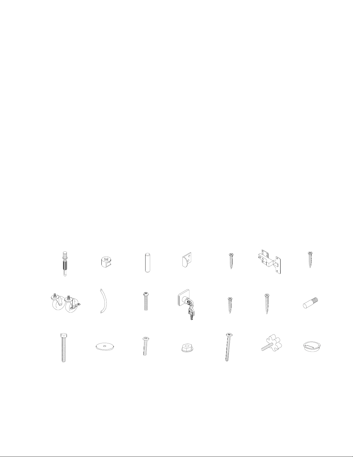
8Part List:
Panel 8 x 2 - Drawer Front
B x 8 - Metal Dowel
I x 2 - Handle
J x 4 - Handle Screws
K x 2 - Lock and Key Set
L x 8 - Lock Screws
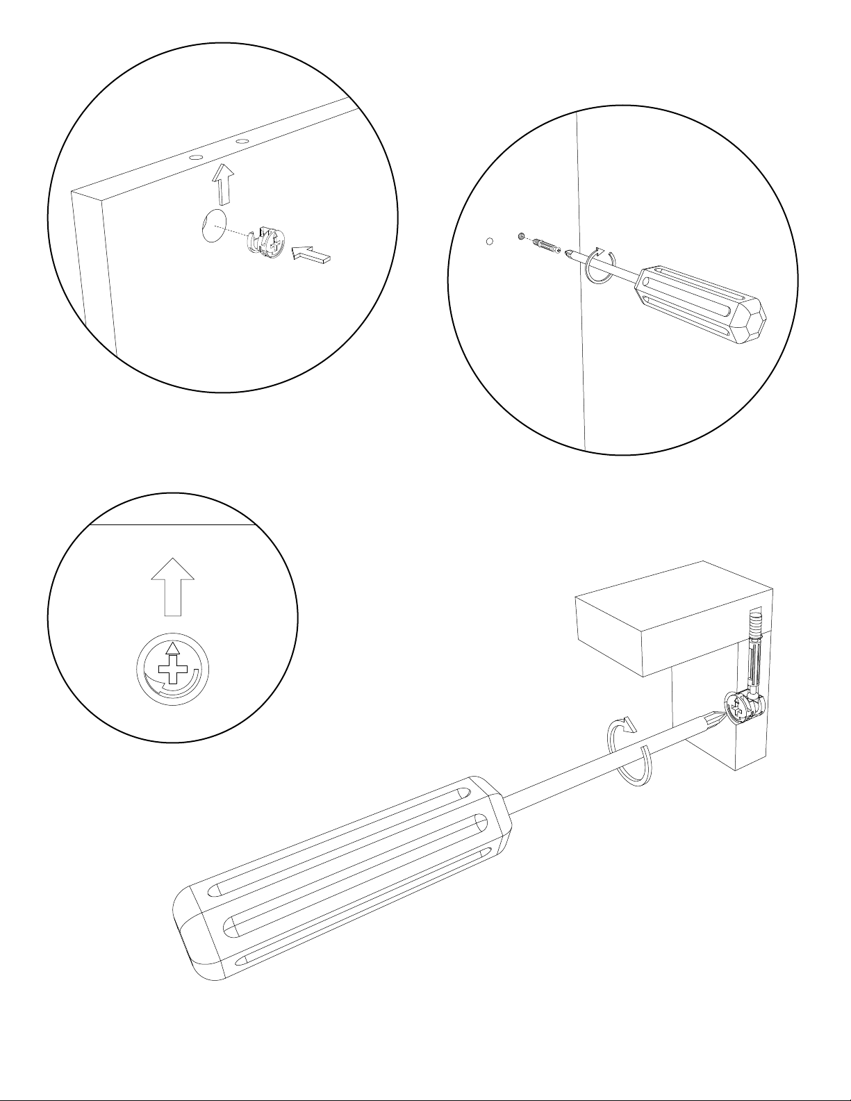
Per Panel - Install 2 cams into
the drawer side panel.
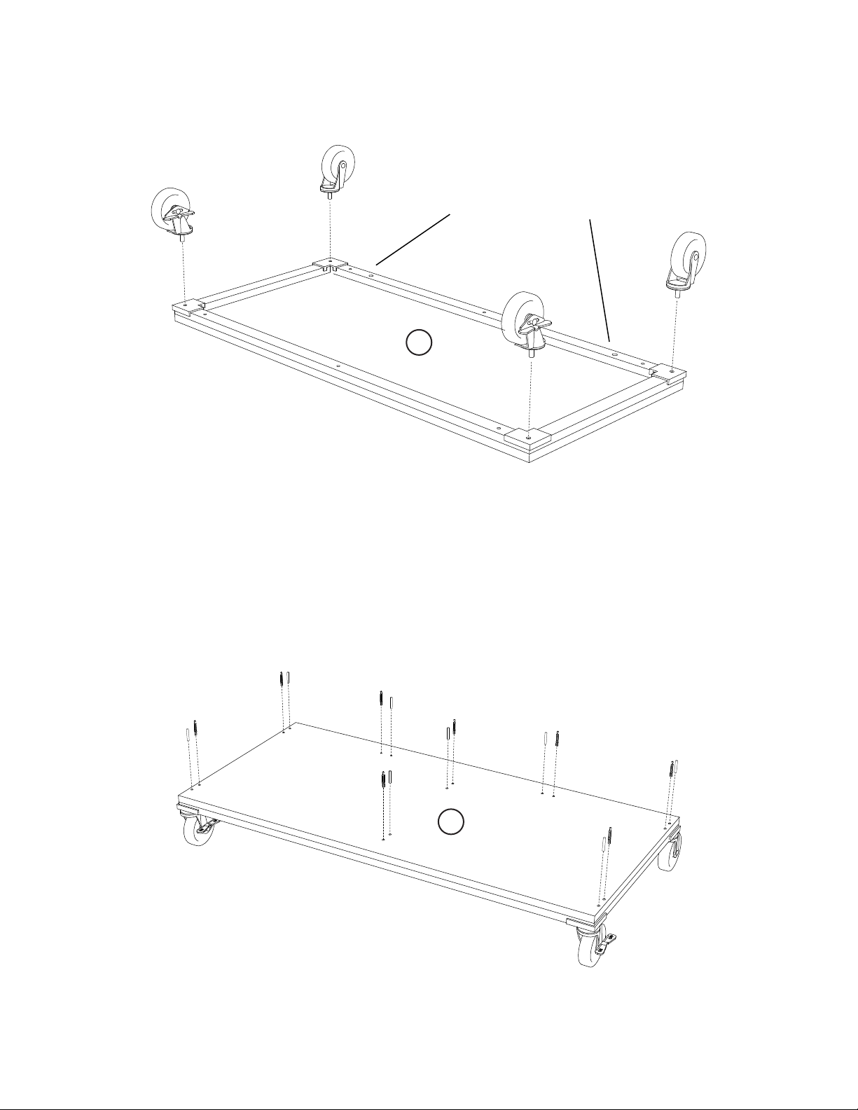
9Part List:
Panel 9 x 2 - Left Drawer Panel
Panel 10 x 2 - Right Drawer Panel
A x 8 - Cam
Per Drawer - Attach the drawer side panels (9 & 10)
to the drawer front panel (8), Grooves face inward.
Tighten the cams onto the dowel. Insert the
Drawer bottom (11) into the drawer assembly.
10 Part List:
Panels 8,9,10,11 x 2 - Drawer Panels
Per Drawer - Place the drawer back panel to the
back of the drawer assembly, keep the top edge
of the side and back panels ush. Secure in place
with 4 drawer screws.
11 Part List:
Step 10 Drawer Assembly x 2
Panel 11 x 2 - Drawer Back
M x 8
I
J
J
K
L x 4
B x 2
A x 2
B x 2
Per Panel - Install 4 metal dowels.
Install the handle and secure with 2
handle screws. Install the lock with
4 lock screws.
8
9
10
M x 2
M x 2
11
12
Outer
Collar
8
910