H2O International Guard U1000 Service manual

INSTALLATION & INSTRUCTION MANUAL
UNDER COUNTER
DRINKING WATER SYSTEM
1 & 2 STAGE SYSTEMS

TABLE OF CONTENTS
2
Initial Inspection....................................................... 3
Operation Parameters............................................. 4
Plumbing Schematic............................................... 5
Pre-Installation .......................................................... 6
Faucet Installation................................................ 6-8
FeedWater Adapter Installation ...................... 8-9
Unit Placement & Mounting.............................. 10
Flowlok Leak Control Valve................................ 10
Tubing Connections....................................... 11-12
System Start Up...................................................... 13
Flushing the System ............................................. 13
Filter Replacement ................................................ 14
Troubleshooting .................................................... 15
Liability & Warranty............................................... 17
CAUTION / WARNING
EYE PROTECTION
ELECTRICAL WARNING
FRAGILE
LEGEND
WARNING: READ ENTIRE MANUAL. FAILURE TO FOLLOW ALL GUIDES
AND RULES COULD CAUSE PERSONAL INJURY OR PROPERTY DAMAGE.
Check with your state and/or local public works department for plumbing codes.
You must follow their guides as you install the Water Filtration system.
NOTE: Failure to comply with these installation instructions will void the product Warranty,
and the installer will be responsible for any service, repair or damages caused thereby.
WARNING: DO NOT USE WITH WATER THAT IS MICROBIOLOGICALLY UNSAFE OR OF
UNKNOWN QUALITY WITHOUT ADEQUATE DISINFECTION BEFORE OR AFTER THE SYSTEM.

INITIAL INSPECTION
3
TOOLS & MATERIALS NEEDED
FOR NORMAL INSTALLATION:
If the above tools are not available, contact your local dealer/distributor for assistance.
WATER FILTRATION SYSTEM INCLUDES:
• Cordless Drill
• Carbide grinding burr
• 1/4” (6 mm) drill bit
• 7/16” (11 mm) drill bit
• 1/2” (13 mm) and 5/8” (16 mm) open-end
wrenches (or adjustables)
• Phillips screwdriver
• Flashlight or droplight
• Teon tape
• Protective eye wear (i.e. goggles)
1. Filtration system* - ( 1 Stage and 2 Stage available )
2. Faucet - (with mounting hardware)
PARTS (already pre-installed in system)
3. Connection Tubing - (Pre-installed)
4. SHOKBLOK - (Pre-installed)
5. Cartridges** - (Pre-installed)
ACCESSORIES (Included in installation packet)
6. Feedwater Adapter
7. Ball Valve
8. FLOWLOK (U.S.A patent pending)
* U2000 - 2 Stage Under the Counter Model shown. ** Pre-installed Cartridges vary per Water Filtration System models.
1
5
32 6
7
8

OPERATION PARAMETERS
4
WARNING!!
The following conditions for feed water supply must be met or Warranty will be void.
1. Unit MUST be connected to a municipal or well water source that is treated and tested
on a regular basis to insure water is microbiologically safe.
2. Operating temperatures:
Maximum: 105° F (40.6° C)
Minimum: 33° F (0.55° C)
3. Inlet Pressure MUST NOT EXCEED 80 PSI (5.6 kg/cm2)
CAUTION!!
DO NOT ALLOW SYSTEM TO FREEZE. The membrane always contains water and
will be destroyed if frozen.
WARNING!!
DO NOT PLUMB SYSTEM TO HOT WATER. This will damage filters and void the
Warranty and manufacturer’s responsibility.
4. Operating pressure:
Maximum: 80 PSI (5.6 kg/cm2)
Minimum: 40 PSI (2.95 kg/cm2)
This drinking water system is designed to operate at a water pressure in the range of:
40 to 80 PSI (2.95 kg/ cm2 to 5.6 kg/ cm2).
• At pressures lower than this, the quantity as well as quality will be reduced.
• At higher pressure, severe, damage to the system may result.
A pressure regulator MUST be installed on the feed water source, which reduces the water
pressure coming into the system.
WARNING!!
Warranty voided and manufacturer assumes no responsibility for damage to
system or property if pressure exceeds 80 PSI.
5. Turbidity: <5 NTU
6. pH: 4 to 11
• Sulde, Iron and Manganese: less than 0.01 ppm.
• Chlorine In Water Supply: less than 2 ppm.
• Water Supply pH Limits: 4-11.
• Turbidity: 1 NTU Max.
RECOMMENDATION: If your water hardness exceeds 7 grains per gallon, or 120 PPM you may wish to purchase a
water softener. Contact your local dealer or distributor for pricing and availability.
7. Recommended Total Dissolved Solids (TDS) NOT TO EXCEED 2000 ppm.

PLUMBING SCHEMATIC
5
BLUE TUBE
( To Faucet )
FAUCET
WHITE TUBE
(To Water Supply)
FEEDWATER
ADAPTER
COLD WATER
METAL BALL
VALVE
FLOWLOK
PLUMBING SCHEMATIC FOR 1 & 2 STAGE
UNDER COUNTER FILTER SYSTEMS
(U2000 - 2 Stage Under the Counter Model shown).
CAUTION!!
DO NOT USE WITH WATER THAT IS MICROBIOLOGICALLY UNSAFE
or of unknown
quality without adequate disinfection before or after the system.

PRE & FAUCET INSTALLATION
6
DIAGRAM A
IMPORTANT!!
PLEASE READ, FOLLOW AND SAVE THIS INSTRUCTION MANUAL.
1. PREINSTALLATION PROCEDURE
1. This unit includes a standard sink top faucet without
an air-gap. In localities where
plumbing codes require
installation of an air-gap, contact your local distributor to
obtain a code approved drain line adapter.
2. The water filtration system may set on the oor of the sink
cabinet. It must be positioned to allow access for service
and lter changes. The assembly should be relatively near
the faucet to maximize ow rate. (See DIAGRAM A for a
positioning example.)
3. The faucet should be positioned to allow a free flow
pattern into the sink. It must be positioned to allow
ready access to the mounting hardware under the sink.
(See DIAGRAM A for a positioning example.)
2. FAUCET INSTALLATION
CAUTION!!
Extreme care must be taken in drilling the hole for the sink-top faucet. The surface
material of most sinks is extremely hard and brittle and can be easily chipped or cracked.
If you are uncomfortable performing the following procedure it is recommended that your local
distributor or experienced plumber be consulted for techniques, installation or other assistance.
The system’s manufacturer accepts no responsibility for sink top damage resulting from system
installation. EXTREME CAUTION SHOULD BE TAKEN WITH GRANITE, MARBLE AND LIKE MATERIAL.
CAUTION!!
Before grinding or drilling put on appropriate eye protection (i.e. goggles)
to protect yourself from porcelain or metal chips.
CAUTION!!
To avoid damaging the sink, consult a qualied plumber or installer for drilling
procedures. Special drill bits may be needed for porcelain or stainless steel.
WARNING:
Many homes are electrically grounded through the plumbing. To protect yourself
from serious injury or fatal shock, use a battery-powered hand drill only to make the hole. DO
NOT USE AN ELECTRIC DRILL.
1. BEFORE DRILLING: Check under the sink in the area that you plan to install the faucet
and make sure that there is a at surface to secure the mounting hardware. A at space of
approximately 2 inches in diameter is needed.
RECOMMENDATION: Before drilling or grinding mask o the immediate area surrounding the grinding/drilling
location preferably with duct tape or if duct tape is unavailable masking tape may be used. This procedure should
help prevent scratching of the sink surface.
(Continues on page 7...)

FAUCET INSTALLATION
(Continued)
7
2. REMOVE EVERYTHING FROM INSIDE THE SINK AND SURROUNDING AREA. Place paper
towels in the sink to catch the shavings from the grinding and drilling.
3. Using a cordless drill with a carbide grinding burr, gently grind away enough porcelain or
enamel to more than accommodate the 7/16” (11 mm) drill bit. Approximately the size of a
dime. Enough surface material must be removed to expose the base metal.
CAUTION!!
Porcelain or enamel must be completely removed in the drilling area to prevent
immediate dulling of drill bit.
4. Remove everything from under the sink.
5. Place newspaper or paper towels directly under drilling location in order to catch the
drill shavings.
6. Using the 1/4” (6 mm) drill bit, drill a centering or pilot hole in the center of the desired
faucet location.
NOTE: this centering/pilot hole will make it easier for the 7/16” (11 mm) drill bit to cut through the sink. Operate the
drill slowly and carefully— Especially when the drill bit is about to penetrate the metal. Otherwise, damage to sink
may occur. Use lubricating oil to keep the drill bit cool while drilling.
7. Discard paper towels and newspaper used in sink and below sink. Be very careful not to
drop any shavings in sink or on the oor as they will oxidize and stain surfaces very quickly.
HELPFUL HINT: If you notice any rust spots from dropped shavings you should be able to get rid of them by scrubbing
them with a cleaning chemical.
8. Coverthedrilled hole withyour nger BE VERYCAREFUL NOT TOCUT YOURSELFONSHARP
EDGES! Rinse sink then scrub with cleaner to prevent any rusting from shavings and to
prepare for faucet installation. Plug hole again while rinsing o cleaner. Hole must be
plugged in order to avoid water dripping below into sink cabinet, which may cause damage.
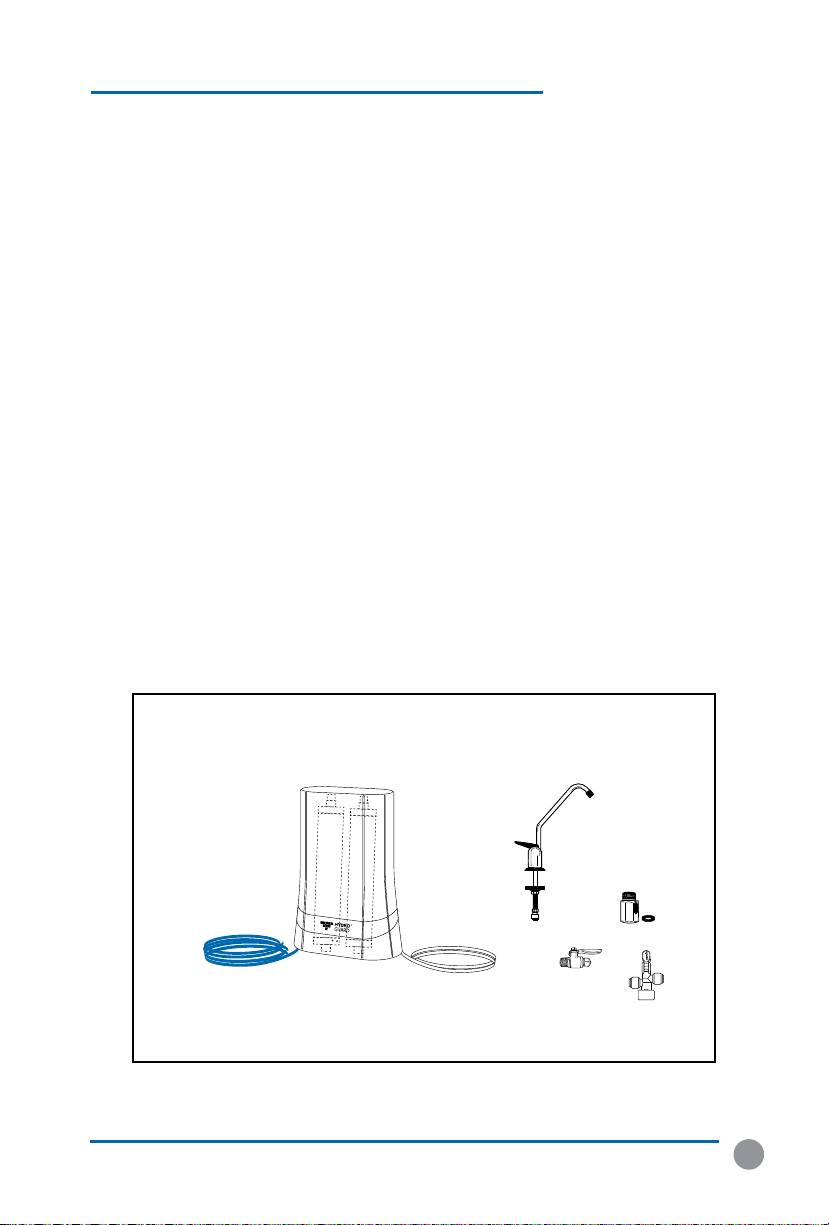
9. Remove faucet from package.
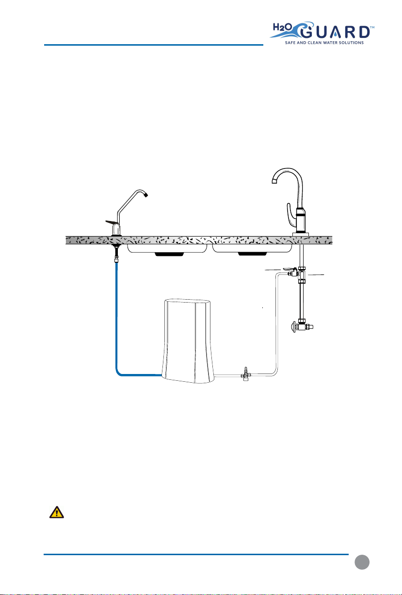
For steps 10-14 refer to DIAGRAM B on page 8.
10. Slip the small, thin rubber gasket over the faucet shank. Next slip the chrome trim plate
(escutcheon plate) over the faucet shank. Finally, slip the large, thin rubber gasket over the
faucet shank.
11. Take the faucet spigot and insert it into the faucet base in the hole next to the faucet
handle. Push the faucet spigot in until it stops.
12. Place the faucet shank complete with only hardware installed in step 11 though the drilled hole.
13. From under the sink slip the large, black plastic, locating washer over the faucet shank.
Next, slip the lock washer over the faucet shank followed by the thin chrome nut.
14. While holding the faucet assembly above the sink tighten the chrome nut below the sink
with an adjustable wrench. Tighten the chrome nut until the faucet assembly does not move.
CAUTION!!
DO NOT OVERTIGHTEN THE CHROME NUT. Overtightening can cause damage to
the sink or faucet assembly.

STAR LOCK WASHER
SHANK
PLASTIC SLEEVE
BLACK PLASTIC WASHER
CHROME NUT
COMPRESSION NUT
SMALL
BLACK GASKET
CHROME WASHER
RUBBER GASKET
UP FOR
CONSTANT
FULL FLOW
DOWN FOR
CONTROLLED
FLOW
MIDDLE POSITION
FOR OFF
BLUE TUBE
1/4” TUBE INSERT
DIAGRAM B
(For Faucet Installation Steps 10-14)
DIAGRAMS B, C, D, & E
8
Cold Water
Line
TURN OFF
WATER FIRST!
Cold Water
Line
TURN OFF
WATER FIRST!
Connect Metal Ball Valve
to the feedwater connector
Connect Metal Ball Valve
to the feedwater connector
Insert washer
into bottom of the
feedwater connector
Insert washer
into bottom of the
feedwater connector
Filter Tubing
(Blue Tube)
Filter Tubing
(Blue Tube)
DIAGRAM D
Cold Water
Line
TURN OFF
WATER FIRST!
Cold Water
Line
TURN OFF
WATER FIRST!
Connect Metal Ball Valve
to the feedwater connector
Connect Metal Ball Valve
to the feedwater connector
Insert washer
into bottom of the
feedwater connector
Insert washer
into bottom of the
feedwater connector
Filter Tubing
(Blue Tube)
Filter Tubing
(Blue Tube)
DIAGRAM E
Cold Water
Line
TURN OFF
WATER FIRST!
Cold Water
Line
TURN OFF
WATER FIRST!
Connect Metal Ball Valve
to the feedwater connector
Connect Metal Ball Valve
to the feedwater connector
Insert washer
into bottom of the
feedwater connector
Insert washer
into bottom of the
feedwater connector
Filter Tubing
(Blue Tube)
Filter Tubing
(Blue Tube)
DIAGRAM C

FEEDWATER ADAPTER
9
3. INSTALLATION OF FEEDWATER ADAPTER
CAUTION!!
For your safety and protection, do not use where water is microbiologically unsafe
or of unknown quality. The water supply to your system MUST be from the COLD WATER LINE!
Hot water will severely damage your filtration system!
1. Turn off cold water supply to the sink using the supply valve located under the sink.
NOTE: In some cases the supply valve may leak or may not work at all. If this happens turn o the water at the main
water shut o for the entire house. In extreme cases the house shut o valve does not work. If this happens shut the
water o at the street and replace the defective valves immediately. Locate the type of shut o valve you have under
your sink and follow that step for connecting the feedwater.
2. Some shut off valves have an extra port for an
icemaker hookup.You will not need the
feedwater adapter for this type of installation. ( See DIAGRAM C )
3. On some shut off valves you can install the feedwater adapter directly to the valve. Slip
the black washer into the feedwater adapter. Tighten feedwater adapter to the valve
with an adjustable wrench. Tighten until snug. Insert the 1/4” nylon elbow fitting into
the feedwater adapter. TIGHTEN BY HAND ONLY! DO NOT OVERTIGHTEN!
( See DIAGRAM D
Most under sink shut off valves have a built in smooth or corrugated riser going up
to the faucet. (Refer to DIAGRAM E for help with this type of valve.)
Secure an adjustable wrench to the fitting on the cold water side of the sink faucet --
NOT THE WATER SYSTEM FAUCET! Secure another adjustable wrench to the smooth/
corrugated riser line nut. Gently undo the riser line from the sink faucet. Do not be
alarmed! There will be water left in the line—this is normal. However, if the flow
does not stop you probably haven’t shut the water off properly.
(See the NOTE in Step # 1, Section # 3 if you need help with water shut off.)
4. Insert the black rubber washer into the feedwater adapter. Screw the adapter onto
the fitting coming from the cold water side of the sink faucet. Using two adjustable
wrenches tighten the feedwater adapter to the cold water line. Take extreme care not
to twist or damage the connection to the cold water connection.
CAUTION!!
Tightening the connector improperly to the faucet could cause irreparable damage
to the faucet.
5. Connect the riser from the water shut o valve to the feedwater adapter. Ensure that the
cone washer on the riser tube is in good condition. With one adjustable wrench on
the feedwater adapter and another adjustable wrench on the riser nut connect the riser
to the feedwater adapter. DO NOT OVERTIGHTEN! This can cause damage to the riser
connection.
6. Insert the 1/4” nylon elbow fitting into the feedwater adapter. TIGHTEN BY HAND
ONLY! DO NOT OVERTIGHTEN!

4. WATER FILTRATION SYSTEM PLACEMENT AND MOUNTING
1. The system does not need to be mounted on the wall of the cabinet and simply sits on
the oor of the cabinet.
IMPORTANT!!
Be very careful not to kink any of the tubing on the water filtration system.
If tubing is kinked the tubing can rupture and leak.
10
5. INSTALLATION OF FLOWLOK LEAK CONTROL VALVE
FLOWLOK is a specially designed shut off valve that turns off your water when a leak is
detected. The FLOWLOK valve uses a compressed textile disc which expands upon water
contact and pushes the valve lever up to the closed position to stop all water flow into the
drinking water system.
NOTE: The FLOWLOK will not shut off any water leak originating from the stop valve or any other connection
which feeds water to it. FLOWLOK is designed to shut off water which is going into the drinking water system.
(Please note that you can order replacement textile discs through you local dealer in case a disc accidentally
becomes wet and expands.)
WARNING!!! The FLOWLOK valve MUST be installed to prevent any water leaks occurring
from the drinking water system. Failure to install the FLOWLOK valve will automatically void
the product warranty.
1. Locate compressed textile disc and set aside.
2. Place FLOWLOK 2 inches from side wall of
cabinet and 4 - 6 inches from the drinking
water systems inlet side.
3. Ax the FLOWLOK with screws to the cabinet
base (oor) with screws.
4. Lift FLOWLOK Lever to o position.
5. Once final connection is made, remove lever
pusher and insert textile disc with the
pronounced part towards the bottom and
reinsert lever pusher. Lower on/o lever to
allow water to ow thru the system.
UNIT PLACEMENT & FLOWLOK INSTALLATION
WHITE TUBE
(to system INLET)
WHITE TUBE
(from FEEDWATER ADAPTOR)
ON OFF
ON/OFF
LEVER
COMPRESSED
TEXTILE DISC
SCREWS LEVER
PUSHER
(U.S.A patent pending)

11
TUBING & QUICK CONNECT FITTINGS
HOW TO MAKE QUICK CONNECT
FITTINGS CONNECTIONS
1. CUT THE TUBING
-Cut the tube cleanly and squarely. Ensure that the tube has a smooth outside diameter
without any burrs, chamfers or score marks prior to inserting it into the tting. Tubing
that has not been cut properly can cause drips and leaks.
(Continues on page 12...)
CORRECT
INCORRECT
6. TUBING CONNECTIONS
IMPORTANT!!
Be very careful not to kink any of the tubing on the water filtration system.
If tubing is kinked the tubing can rupture and leak.
CONNECTING THE SYSTEM:
(BLUE TUBING - From system faucet port. This is from port labeled faucet)
1. Connect the blue tubing to the faucet by slipping the 1/4” chrome nut over the tubing
followed by the nylon ferrule.
NOTE: It is not necessary to have a 1/4” nylon insert in this line as it would restrict the ow through the faucet.
2. Push the blue line all the way into the faucet stem and tighten the chrome nut.
DO NOT OVERTIGHTEN!!
CONNECTING THE FEEDWATER:
(WHITE TUBING - From System inlet port)
1. If you installed the feedwater adapter using step # 3 or # 4 in Section # 3 simply slip a
chrome nut over the end of the tubing from the metal ball valve with blue lever.
Then insert the end of the extra white tubing into the barb of the ball valve on the feedwater
adapter. Tighten the chrome nut securely. DO NOT OVERTIGHTEN!
2. If you have the connection for the icemaker tee as in Step # 2 of Section # simply slide the
1/4” chrome nut over the blue tubing. Slip the nylon ferrule over the blue tubing and
insert
the 1/4”nylon insert into the tubing end. Insert tubing into the cold water shut o valve and
tighten securely. DO NOT OVERTIGHTEN!

12
QUICK CONNECT FITTINGS
HOW TO MAKE QUICK CONNECT FITTINGS
CONNECTIONS:
(Continued)
1. INSERT TUBING
Push the tubing through the collet and o-rings until it bottoms out against the tube stop.
The collet holds the tube in place and the o-ring provides a leak resistant seal. If you need
to remove the tubing always re-cut before connecting tubing again. Scores on tubing can
cause failure.
2. INSPECT AND TEST
Push and pull the tubing toward and away from the tting to ensure that it has been
installed properly. Test and inspect the installation for any leaks.
3. TUBE REMOVAL
Relieve pressure from the tubing and tting. Push the collet ange against the tting body
while pulling the tubing away from the tting to release it.
CAUTION!!
IT IS RECOMMENDED THAT TUBING AND QUICK CONNECTION FITTINGS
INSTALLATIONS ARE INSPECTED A MINIMUM OF ONCE PER YEAR AND PARTS REPLACED AS NEEDED.
Tubing Collet O-Ring Quick Connect Fitting
Tube Stop

BALL VALVE
MAIN WATER
SHUTOFF
13
SYSTEM START UP & FLUSHING RO SYSTEM
7. SYSTEM STARTUP
1. With all connections complete, turn on the cold water supply to the filtration system
IMPORTANT!!
The Water Filtration Systems Main Water Shut O valve (indicated by the
bright orange tag at the side of the unit) must be open. This means the blue handle on the
valve must be in the horizontal position.
2. Immediately check entire water ltration system for leaks. If you notice any leaks turn o
cold water supply and x the leak.
8. FLUSHING THE WATER FILTRATION SYSTEMS
1. Open the ltration system faucet and let water run for 5 minutes.
CAUTION!!
If installing the unit in new construction, ensure that house plumbing is ushed
thoroughly before opening the water supply valve.
WARNING!!
Discard all unused parts and packaging material after installation. Small parts
remaining after the installation could be a choke hazard.

14
14
FILTER REPLACEMENT
9. FILTER REPLACEMENT INSTRUCTIONS
(U2000 - 2 Stage Under the Counter Model shown).
STEP 11
TURN WATER BACK ON
Turn Ball Valve Main Water Shut-O
Blue handle to horizontal position
STEP 12
STARTUP & FLUSH
Follow Section 6 steps
on page # 13
STEP 10
FLIP OVER & CLOSE
Flip system and replace
logo band and cover
UNPLUG BATTERY
Unplug battery
connector
STEP 7
UNSCREW & REPLACE
Unscrew battery case
and replace batery
STEP 8
SCREW & PLUG
Screw back battery case
and plug battery connector
STEP 9
UNSCREW HOUSING
Unscrew filter housing
and remove filter
STEP 4
REPLACE FILTER
Replace with
new filter
STEP 5
SCREW HOUSING
Screw back
housing
STEP 6
TURN WATER OFF
Turn Ball Valve Main Water Shut-O
Blue handle to vertical position
STEP 1
OPEN SYSTEM
Remove cover and
Hydro Guard™ logo band
STEP 2
FLIP SYSTEM
Flip system and
place in small bucket
STEP 3

15
TROUBLESHOOTING
TROUBLESHOOTING
LOW WATER PRESSURE FROM DISPENSING FAUCET
POSSIBLE CAUSE / SOLUTION
Carbon Post Filter is clogged. Replace Post Filter.
The Faucet is out of
adjustment or faulty. Repair or replace Faucet.
TASTES AND ODORS IN PRODUCT WATER
POSSIBLE CAUSE / SOLUTION
Carbon Post Filter is
exhausted. Replace Filter.
Dissolved gases in feed water. Pre-treat feed water to remove gases.
FAUCET LEAKS OR DRIPS
POSSIBLE CAUSE / SOLUTION
Water leaks from faucet spout.
Adjust faucet by turning the tee bar located under the handle
to provide a small amount of free play in the handle when
shut o. Should this not work, repair or replace the faucet.
Leaks from beneath the handle.
Repair or replace the faucet.
NO WATER
POSSIBLE CAUSE / SOLUTION
Water is shut off at stop valve Open main stop valve. (See diagram on page 13)
POSSIBLE CAUSE / SOLUTION
Feed water valve is plugged
or closed. Open valve or unclog.
Sediment/Carbon prelter or
Carbon Post Filter is clogged. Replace Filters.
Low incoming water pressure.
Incoming water pressure must be above 40 PSI. Install
a Booster Pump or Permeate Pump.
NOT ENOUGH WATER

16
DATE CARTRIDGE
#1
CARTRIDGE
#2
CARTRIDGE
#3
CARTRIDGE
#4
SERVICE RECORD
SERVICE RECORDS

17
LIABILITY & WARRANTY
LIABILITY
WARNING!!!
The installer is responsible for any leaks resulting from installation of tubing or
related ttings. THE I NSTALLER M UST CHECK OVER T HE ENTIRE SYSTEM COMPLETELY WHILE
UNDER PRESSURE TO ENSURE SYSTEM IS NOT LEAKING AND FUNCTIONING PROPERLY.Liability
resulting from failure to check for leaks under pressure is the sole responsibility of the installer.
WARRANTY
THREE YEAR LIMITED Warranty ON DRINKING WATER SYSTEM
(Except filter cartridges and R. O. membrane)
Warrantor: Hydro Guard Water Sciences Ltd. - PO BOX 2235 Chino, CA 91709, USA
Warrantor guarantees, to the original owner, that the Drinking Water System, when installed
and maintained in accordance with the instructions, will be free from defects in materials and
workmanship for a period of one year from date of installation. If, within the first year, a part
proves, after inspection, to be defective, Warrantor will, at its sole option, either replace or repair
the part without charge except normal shipping and installation charges. Labor to maintain the
equipment is not part of the Warranty. Filters and membranes, which are expendable, are not
covered by the Warranty.
This Warranty applies only while this product is in use in the United States or Canada.
General Provisions
The above warranties are effective provided the Drinking Water System is operated at water
pressures not exceeding 80 psi, and at water temperatures not exceeding 113°F; provided further
that the Drinking Water System is not subject to abuse, misuse, alteration, neglect, freezing,
misapplication, neglect, alteration, water pressure spikes, accident or negligence; and provided
further that the Drinking Water System is not damaged as the result of any unusual force of nature
such as, but not limited to, flood, hurricane, tornado or earthquake. Warrantor is excused if failure
to perform its Warranty obligations is the result of strikes, government regulation, materials
shortages, or other circumstances beyond its control.
*THERE ARE NO WARRANTIES ON THE FILTRATION DRINKING WATER SYSTEM BEYOND THOSE
SPECIFICALLY DESCRIBED ABOVE. ALL IMPLIED WARRANTIES, INCLUDING ANY IMPLIED Warranty
OF MERCHANTABILITY OR OF FITNESS FOR A PARTICULAR PURPOSE, ARE DISCLAIMED TO
THE EXTENT THEY MIGHT EXTEND BEYOND THE ABOVE PERIODS. THE SOLE OBLIGATION OF
WARRANTOR UNDER THESE WARRANTIES IS TO REPLACE OR REPAIR THE COMPONENT OR PART
WHICH PROVES TO BE DEFECTIVE WITHIN THE SPECIFIED TIME PERIOD, AND WARRANTOR IS
NOT LIABLE FOR CONSEQUENTIAL OR INCIDENTAL DAMAGES. NO WARRANTOR DEALER, AGENT,
REPRESENTATIVE, OR OTHER PERSON IS AUTHORIZED TO EXTEND OR EXPAND THE WARRANTIES
EXPRESSLY DESCRIBED ABOVE.
Some states do not allow limitations on how long an implied Warranty lasts or exclusions or
limitations of incidental or consequential damage, so the limitations and exclusions in this
Warranty may not apply to you. This Warranty gives you specific legal rights, and you may have
other rights which vary from state to state. This Warranty applies to consumer-owned installations
only. This Warranty does not cover any equipment that is relocated from the site of its original
installation.

18
NOTES
NOTES

HYDRO GUARDTM
|PO Box 2235 Chino Hills, CA 91709, USA
U1000 SERIES
1 STAGE UNDER COUNTER
DRINKING WATER SYSTEMS
U2000 SERIES
2 STAGE UNDER COUNTER
DRINKING WATER SYSTEMS
U3000 MODELS
U1000-MCB
MICROBAN® CARBON BLOCK
(HDG-MCB)
U1000-CER
MICROCERAMIC
(HDG-CER)
U1000-UF
ULTRAFILTRATION
(HDG-UF )
U4000 MODELS
U2000-GAC/KDF
GAC/KDF BLEND
U2000-MCB
MICROBAN® CARBON BLOCK
U2000-CER
MICROCERAMIC
U2000-UF ULTRAFILTRATION

DISTRIBUTED BY:
This manual suits for next models
1
Table of contents
Other H2O International Water Filtration System manuals
Popular Water Filtration System manuals by other brands

Hellenbrand
Hellenbrand Iron Curtain IC-10 owner's manual

Com-mw
Com-mw ZLPF1-M0-6G-029 quick start guide

Grundfos
Grundfos Oxiperm OCD-164 Installation and operating instructions

3M
3M PS114 installation manual

Pentair
Pentair Everpure QL2-OW200L instructions

Ispring
Ispring UVF11A Installation instructions & user manual

Kohler
Kohler K-78433T-KH200-AF installation guide

BWT
BWT THERO 90PRO Installation and operating instructions

Environmental Water Systems
Environmental Water Systems EWS-1054 Care and use manual

Argo-Hytos
Argo-Hytos FNA 045 manual

Trox Technik
Trox Technik MFE Installation and maintenance manual

EWS
EWS FUGAC200 Care and use manual