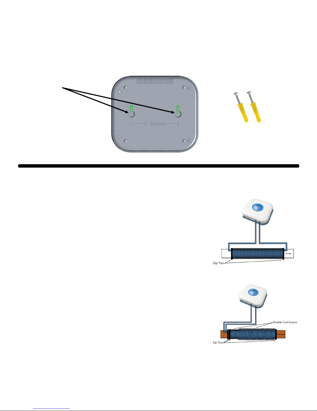
H2oEliteLabs EWC-MAX-i User manual

H2oEliteLabs Max i
Residential model - indoor installation
Operation Manual
H2oEliteLabs.com

2
Table of Contents
Page 2: Table of contents
Page 3: What’s included, Types of pipes that can be used and Elite Max i specs
Page 4: Installaon locaon
Page 5: Mounng the control module, installing the inducon coil
Page 6: Installing the inducon coil, coil chart
Page 7: Coil chart, connecng the power adapter
Page 8: Connecng inducon coil, Features and nocaons
Page 9: Oponal Equipment, Technology and how it works
Page 10: Benets of the H2oEliteLabs Max i
Page 11: Warranty informaon and product support

3
What’s Included
EWC-Elite Max I
Control module
AC adapter (115 volt
class, UL approved)
Signal cable AWG18
(60’)
4 Nylon cable
es
Screws and wall anchors
Types of pipes that can be used with Elite-Max i
Copper Pipe PVC Pipe CPVC Pipe PEX Pipe
Please note: The EWC Max i cannot be used on galvanized pipe or any kind of steel pipe. In the event that galvanized or
steel pipe is present. A secon of the galvanized or steel pipe must be removed and replaced with copper, PVC or PEX
pipe. The inducon coil then has to be applied onto the replaced secon of pipe.
Elite-Max i specifications
• Indoor use only
• Handles up to 35 gpg (grains per gallon) or 598 ppm
• Up to 5,000-sq. . home
• Works on copper, PVC, CPVC and PEX
• Up to 1.25” diameter pipe
• 3-year warranty
• UL/CUL approved
• Can be installed on horizontal or vercal pipe
• Leak detecon capability

4
Installation Location
1. Determine where the main cold water line enters the house or condominium.
2. Apply inducon coil to main cold water line. If the main cold water line is not assessable then apply induc-
on coil to the incoming cold water line to water heater or tankless water heater. Only hot water appliances
will have treatment if the inducon coil is applied to the hot water. In most cases the hot water system is the
main culprit for limescale build up so this line will provide protecon and treatment. (Inducon coil can be
installed on a horizontal or vercal pipe)
3. If there is a water soener loop present the inducon coil can be applied at this locaon also. Addional
plumbing may be required. (This line may or may not treat kitchen faucets or outside spigots)
4. Customers using well water must apply inducon coil aer the pump and pressure tank if present. The
Elite Max i is an indoor only model. Provisions for outdoor locaons must be considered.
5. The Elite Max i can be used in conjuncon with other water treatment systems, lters or water soeners.
The inducon coil must be installed aer this equipment. If using in conjuncon with a water soener you
may keep the water soener online or turn if o by engaging the bypass mode. Under sink ltraon systems
will not eect performance of Elite Max i.
Well pumps Water soener Water soener loop House ltraon
Ideal locaon for
inducon coil

5
Mounting the control module
The control module can be mounted on any type of wall or surface with supplied mounng hardware. Sup-
plied hole template can be used to mark screw spacing. There are two mounng holes located on the back of
the control module.
Mounng holes
with 3”(76.2mm)
center to center
spacing
Installing the induction coil
1. Once the ideal locaon is determined for the inducon coil on the main
incoming cold-water line, then the coil must be wrapped around the out-
side of the pipe. You will need approximately 12” of straight pipe to apply
the inducon coil to.
2. There are two styles of coils applicable, a single layer coil wrapping and
a double layer coil wrapping.
3. When applying the single layer or double layer style coil determine how
long of coiling and layers needed for your size and material pipe (refer to
coil wrap chart on pages 6&7)
4. To begin the coil wrapping, mark the length of the coil needed for your
pipe size and type. Then measure out between 1’and 15’ of wire for the
rst lead to the control module (the lead wires from the coil to the control
module can be no longer than 15’ maximum but can be cut shorter to de-
sired length)
5. The rst lead must be secured to the pipe with the supplied cable es.
6. Once the rst lead wire has been secured with a cable e, begin wrap-
ping the wire around the pipe in any rotaon (clockwise or counter clock-
wise).
7. When nished wrapping the pipe secure the other lead wire with a cable
e as seen in diagram.
Screws and wall anchors
Single layer coil wrap
Double layer coil wrap

6
Installing the induction coil (continued)
9. Installing the inducon coil on copper pipe will need a double layer coil. Wrap the rst layer coil as men-
oned on the previous page.
10. When nished wrapping the rst layer and securing to the pipe with a cable e, then another layer of
wrapping must be applied on top of the rst layer of wrappings with the remaining wire.
11. The second layer of wrappings must be wrapped with the same rotaon as the rst layer of wrappings (if
the rst layer is clockwise then the second layer must be clockwise also or if the rst layer is counter clock-
wise then the second layer must be counter clockwise also).
12. When the second layer is complete secure the wire down to the pipe with a cable e (both wire leads will
exit on the same end of the inducon coil).
Note: Keep inducon coil far away as possible from elbows,
tees and couplings and never wrap coil on top of any ng.
Double layer coil wrap
Coil Chart for PVC, CPVC and PEX
NPS Pipe size Layers Approx. Coil
Length
1/2” Double 4.5”
3/4” Single 8”
1” Single 7”
1 1/4” Single 6”
1 1/2” Single 5.5”
Note: Always
use specied
length and lay-
ers of wraps for
your pipe size.

7
Coil Chart for Copper
NPS Pipe size Layers Approx. Coil
Length
1/2” Double 6”
5/8” Double 6”
3/4” Double 6”
1” Double 5.5”
1 1/4” Double 5”
1 1/2” Double 4.5”
Note: Always
use specied
length and lay-
ers of wraps for
your pipe size.
Connecting the Power Adapter
The control module comes with a 115 VAC power adapter with a 5’ cord. Part number: CUI/SW125-5-N-P5.
Only use supplied power supply. This must be inserted into the power receptacle jack in the boom of the
control module. Once the power adapter is inserted into the control module, plug the power adapter into
the nearest wall outlet. If there is not a wall outlet near, an extension cord can be used.
Power adapter receptacle
CUI/SW125-5-N-P5

8
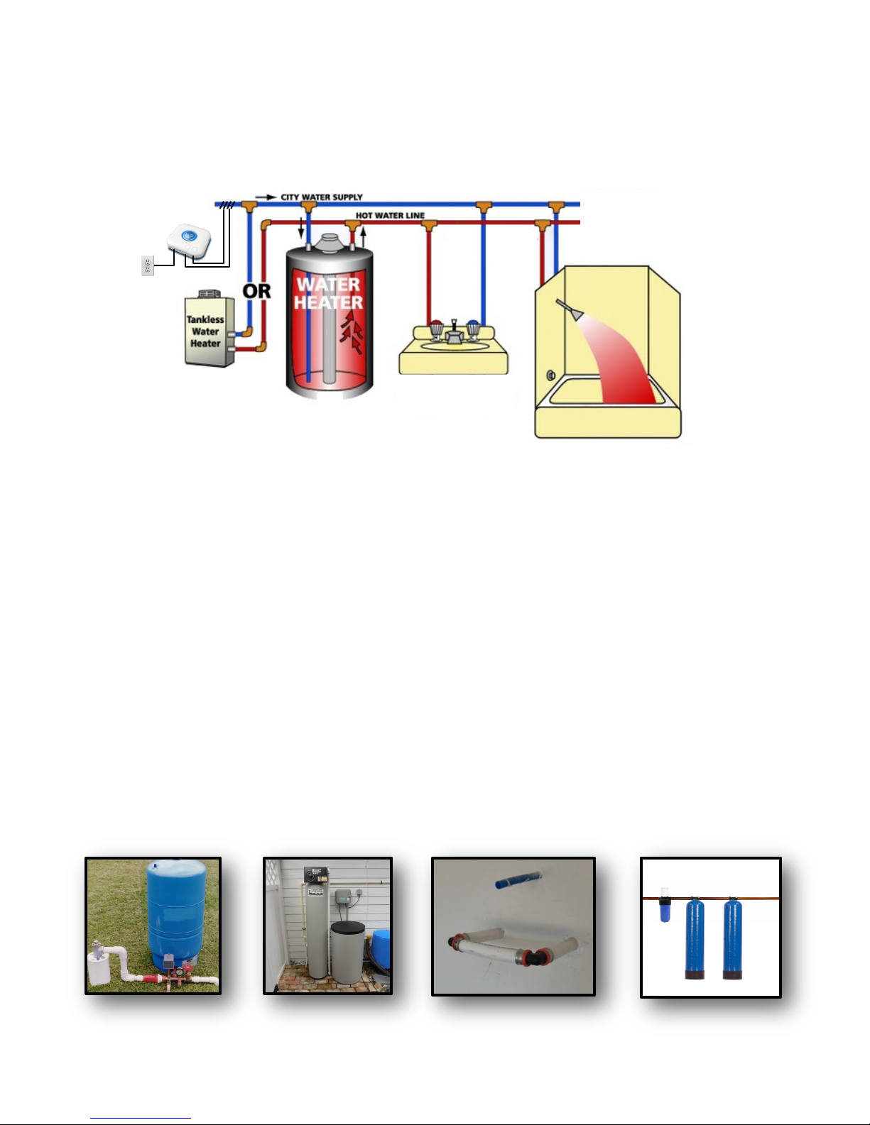
Connecting Induction Coil
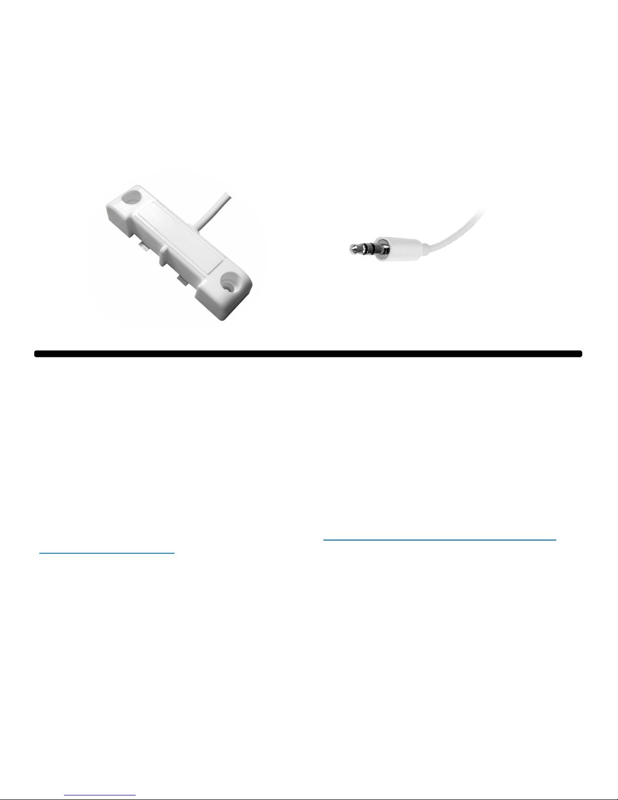
1. Upon compleon of installing the inducon coil, the two wires leading from the inducon coil must be
connected to the control module.
2. You will need to strip approximately .5” of the wire insulaon from each wire.
3. There are two illuminated holes in the boom of the control module to receive the stripped wire ends.
4. To insert the coil wires into the control module there are two illuminated push buons located on the
front of the control module. Press down on the buons one at a me to insert each of the wires into the
control module.
5. Once the buons are released with the wire inserted this will lock the wire into the receptacle. Give the
wire a gentle tug to make sure wires are connected properly.
6. When roung inducon coil leads back to the control module make sure they are not twisted together or
touching each other as much as possible.
7. Make sure the two wires coming from the inducon coil are no longer than 10’ in length. These lines can
be cut shorter to desired length needed.
Features and Notifications
Example of wire with
the insulaon removed
The Elite Max i comes equipped with four color illuminaon and sound nocaons.
1. The buons on the front and wire receptacle holes on the boom of the control module will illuminate
a white light to aid with the installaon of the coil wires.
2. The logo halo will stay solid red unl a coil is detected. Once the coil is detected the logo halo will go to
solid green.
3. The solid green logo halo illuminaon will turn blue to nofy that the Elite Max i is funconing properly.
At this point the buon and coil hole illuminaon will turn o.
4. If in the event the logo halo illuminaon goes to red there is an power issue to the control module.
5. The Elite Max i is equipped with an oponal water leak detecon module.
6. In the event the water leak detecon module detects a leak an audible buzzer will sound and the logo
halo will blink red unl the water leak is reced.
Illuminated buons
and holes for wire
inseron
Solid red logo illuminaon indicates
an power issue or no coil detected,
blinking red indicates water leak
When the coil is connected
and unit is funconing proper-
ly, logo illuminaon will go
from solid green to solid blue

9
Optional Equipment
The Elite Max i is equipped with an oponal water leak detecon module. The water leak detecon module
will alert the user with an audible and visual nocaon in the event of a water leak. The leak detecon
module should be installed on the oor where there is a possibility for water leaks.
Technology and How it works
Our EWC products provide a specifically designed Magnetic and Electric Field with a high-speed
pulse wave on a variety of pipe sizes and materials in Residential, Commercial and Industrial appli-
cations.
This magnetic field creates Nano bubbles (surface diameter less than a micron) that coats the inside
of the pipe and doesn’t allow scale to form.
Hard Scale that forms and is very difficult to remove is Calcite (similar to cement or grout in Harness)
Our Unique approach converts Calcite to Aragonite. Aragonite is a powdery material that can be
easily wiped off surfaces.
Our Magnetic field changes the surface tension of the water and some of the water molecules break
into HO (-) and H (+) ions. This ionic change allows Calcium to bind with OH (-) ions creating Calci-
um Hydroxide Ca(OH)2 which is water soluble.
Calcium Hydroxide is then able to easily be broken done inside the pipe and passed through the
system.
The magnetic field also creates a mechanical component by pulsing the signal 25 times a second.
The signal breaks down existing scale over time and allows it to pass through the pipes
As hard water particles are removed from existing pipes the water pressure will increase and help to
remove existing scale and stop new scale build up on pipes, heating elements, and any other surfac-
es, coming into contact with this water.

10
Benefits of the H2oEliteLabs Max i
The most outstanding feature of the H2oEliteLabs Max i, is that it’s completely maintenance free. No, salt,
no chemicals, no baeries, totally solid state design and no expensive repairs. H2oEliteLabs is environmen-
tally friendly without the use of salt and leaving essenal minerals it is also beer for your health. To har-
ness the full eect of the H2oEliteLabs Max i it may take up to 90 days to completely remove scale buildup
from the enre plumbing system.
The removal of scale build up from pipes and equipment may worsen water quality inially, this is normal.
When the decaling eect removes scale build up from the system in severe cases this may clog up faucet aer-
ators and may have mineral fall out in dishwashers and hot water heaters. It is recommended that water
heaters be purged aer 90 days of using H2oEliteLabs Max i.

11
Warranty information and Product Support
H2oEliteLabs Max i
The H2oElite Max i has a warranty period of 3 years from the date of purchase. Free of
defects in material and workmanship under normal use. This warranty does not extend to
any water or electrical appliances or damaged plumbing nor other damages that occurred
before or aer installaon. The manufacture in no way will be liable for damages from im-
proper installaon or damaged pipes or any other damages directly or indirectly. This war-
ranty is limited to repair or replacement and voids any warranty either expressed or im-
plied.
This warranty does not include damage due to accidents, abuse, tampering, misuse, re,
lightning or any catastrophic acts of God. If malfuncon or failure results the H2oElite Max i
will be repaired or replaced by the manufacture and returned to the original owner for a
period of 3 years from the date of purchase. This warranty is limited to the original retail
purchaser and is non transferable.
To claim your warranty
Please call 800-940-8424
You must retain your original receipt of purchase to claim your warranty
Please ll in and retain for your records
Purchase date: ______________________ Serial #_______________________
Aach your original receipt here:
If you have any queson regarding installaon or general in-
formaon about H2oElite Max i, please contact us via email at
or 727-221-7463 Monday - Friday, 8am to 5pm Eastern

12
H2oEliteLabs.com
800-940-8424
This manual suits for next models
1
Table of contents
Popular Water Dispenser manuals by other brands

LF
LF Matic Instruction and maintenance

Kinetico
Kinetico 2030s installation instructions

Olympia Water Systems
Olympia Water Systems OROS-50 Installation instructions & owner's manual

Everpure
Everpure RT-9 Specifications

icetro
icetro ID-0300-AN user manual

Elkay
Elkay VRCGNDWS C Series Installation, care & use manual