HACKADAY MicroKits User manual

Theremin Electronics Kit
MicroKits

2 3
Sample ©2017 Microkits
MicroKits.cc for more info
Greetings, I’m Micro! Today I’ll be helping you build your own circuit.
We’ll be using these parts (including me!) to build a theremin.
We’re building the circuit in three stages. That way, we can check our work as we go.
Don’t worry about making mistakes, because we can fix them along the way. And once
we’re done, you’ll have a really cool way to experiment with physics and music!
Stage 1: Audio
and Power
Stage 2: Pitch
Control
Stage 3: Volume
Control
104
TICK
MICRO
+-
+-
+-
+-
1
5
10
15
20
25
30
1
5
10
15
20
25
30
a b c d e f g h i j
a b c d e f g h i j
+-
+-
+-
+-
1
5
10
15
20
25
30
1
5
10
15
20
25
30
a b c d e f g h i j
a b c d e f g h i j
MICRO
104
+-
+-
+-
+-
1
5
10
15
20
25
30
1
5
10
15
20
25
30
a b c d e f g h i j
a b c d e f g h i j
MICRO
104
TICK
+
-
+
-
+
-
+
-
1
5
10
15
20
25
30
1
5
10
15
20
25
30
a b c d e f g h i j
a b c d e f g h i j
MICRO
104
TICK
Two Resistors
Capacitor
Speaker
A Bunch of Wires
x3
x3
x6
And A Circuit
Building Block
Tick Micro
Two Copper Antennas

4 5
Sample ©2017 Microkits
MicroKits.cc for more info
The theremin creates music at a distance, without touch.
Moving your hand towards the right antenna increases pitch,
and moving towards the left antenna increases volume.
Your theremin senses capacitance to figure out what note to play. Capacitance is how
easy it is to store energy between objects in an electric field. By moving things (like
your hands) closer to the theremin, you increase capacitance.
+-
+-
+-
+-
1
5
10
15
20
25
30
1
5
10
15
20
25
30
a b c d e f g h i j
a b c d e f g h i j
MICRO
104
TICK
P
I
T
C
H
More field lines, more capacitance.
V
O
L
U
M
E

6 7
Sample ©2017 Microkits
MicroKits.cc for more info
The circuit building block holds wires and parts on a
grid. With it, you can make connections without tools.
Each point on the grid has a name. The grid has
rows from 1 to 30 and columns from a to j.
Push the wire or part fully into the correct point.
Examples of correctly placed parts:
This is point H3
The graph to the right shows how different points
are electrically connected inside the building board.
The points act like wires to connect different parts.
Points on the same row of the grid connect
horizontally, but not across the middle.
On each side of the grid are a pair of strips,
marked “+” Positive and “
-
” Negative. These points
connect vertically and will help deliver power to
different parts of the circuit.
+-
+-
+-
+-
1
5
10
15
20
25
30
1
5
10
15
20
25
30
a b c d e f g h i j
a b c d e f g h i j
+-
+-
+-
+-
1
5
10
15
20
25
30
1
5
10
15
20
25
30
a b c d e f g h i j
a b c d e f g h i j
Grid
Power
B24 F28

8 9
Sample ©2017 Microkits
MicroKits.cc for more info
Stage 1: Audio & Power
□Connect A16 to the “
-
”strip using an orange wire.
□Connect J13 to the “+” strip using an orange wire.
Wires connect sections of the building block together,
so that electrical power and signals can flow to parts.
+-
+-
+-
+-
1
5
10
15
20
25
30
1
5
10
15
20
25
30
a b c d e f g h i j
a b c d e f g h i j
MICRO
+-
+-
+-
+-
1
5
10
15
20
25
30
1
5
10
15
20
25
30
a b c d e f g h i j
a b c d e f g h i j
MICRO
Micro can be programmed to do different
things, like being a theremin!
□Place the building board with Row 1 on top.
□Find me, Micro. I have 8 metal legs, called pins.
Place the pins in rows 13 to 16 and column E & F.
Make sure I lay flat on the block, and make sure
my eyes point down. Direction matters!
MICRO

10 11
Sample ©2017 Microkits
MicroKits.cc for more info
□Connect B14 to B22 with a gray wire.
□Connect J22 to the “+” strip using an orange wire.
□The speaker has two pins. Place the pins on row
22, in columns E & F (either direction will work).
□Place the capacitor between the “+”strip and
the “
-
”strip in the location shown.
□Connect the “
-
”strip on the left to “
-
”on the
right using a long blue wire.
□Connect the “+”strip on the left to “+”on the
right using a long red wire.
+-
+-
+-
+-
1
5
10
15
20
25
30
1
5
10
15
20
25
30
a b c d e f g h i j
a b c d e f g h i j
MICRO
+-
+-
+-
+-
1
5
10
15
20
25
30
1
5
10
15
20
25
30
a b c d e f g h i j
a b c d e f g h i j
MICRO
104
104

12 13
Sample ©2017 Microkits
MicroKits.cc for more info
□Find the switch on the battery pack. For now, make sure it is set to “OFF”.
□Open the battery holder and install three new AA batteries. Check the battery
holder to see the correct way to place the batteries.
□The battery pack has two wires. Plug the red wire into the “+”strip and the black
wire into the “
-
”strip, as shown. Direction matters!
□Double check your progress to make sure everything is connected correctly:
+-
+-
+-
+-
1
5
10
15
20
25
30
1
5
10
15
20
25
30
a b c d e f g h i j
a b c d e f g h i j
MICRO
104
□No loose wires or parts
□Parts are in the correct spot
□Battery plugged in correctly
□Micro facing correct direction
OFF - ON
Black to “
-
”
Switch
Red to
“+”

14 15
Sample ©2017 Microkits
MicroKits.cc for more info
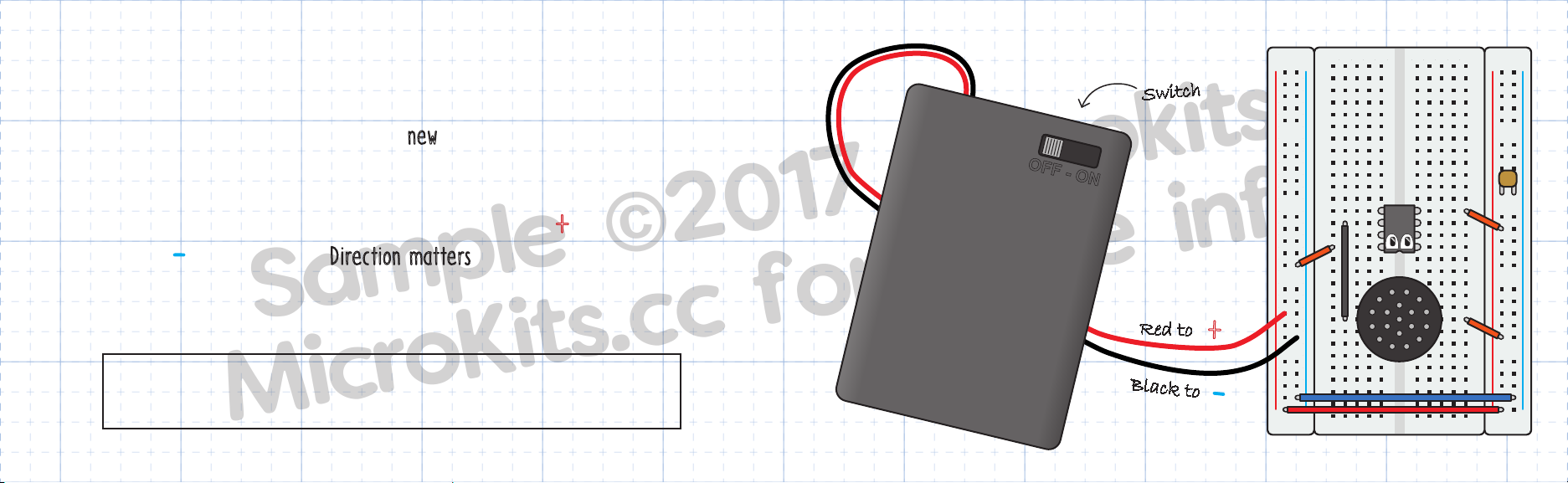
Important: Turn the power “OFF” immediately if the circuit does not
work. Leaving power on could damage or overheat the battery or Micro.
When you’re ready, turn the power “ON”. What happens? You’ll know your circuit is
working when the you hear a tone! This means that power and speakers work.
If nothing happens, don’t worry! Just turn the power “OFF” and check for mistakes,
a process called troubleshooting. With a bit of looking you’ll find what to fix.
♪
!
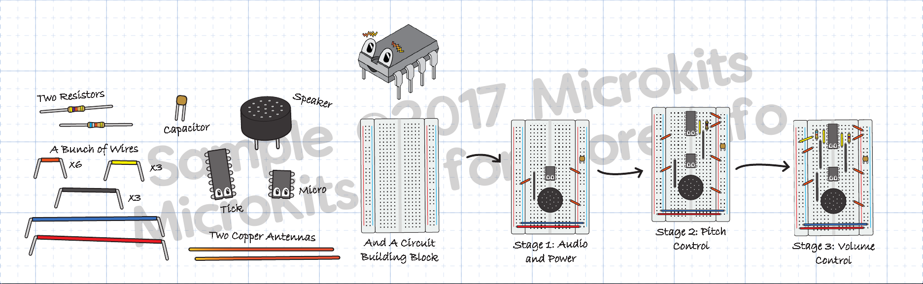
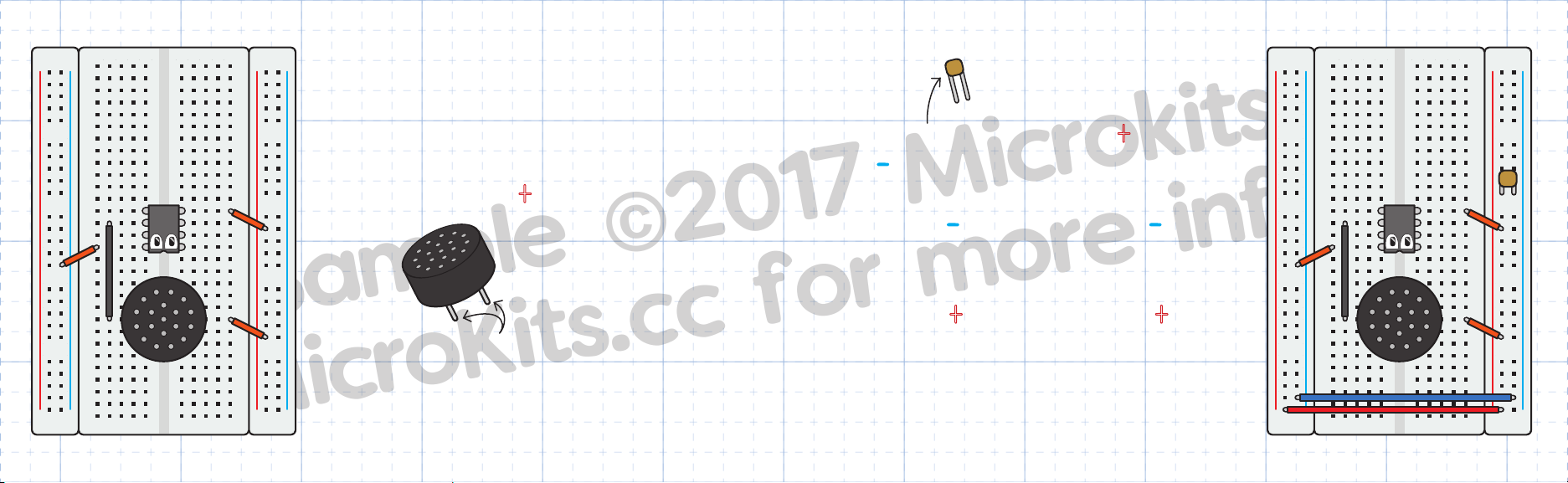
Let’s think about what’s going on. Right now, I’m connected to a
speaker, a battery, and a capacitor. The battery gives me power, and
the capacitor stores extra energy for when I need it most.
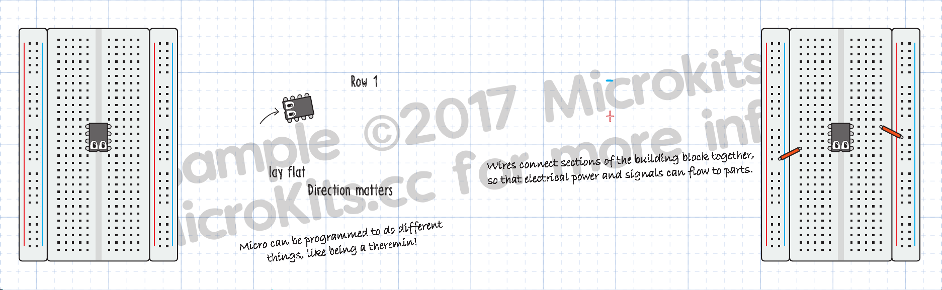
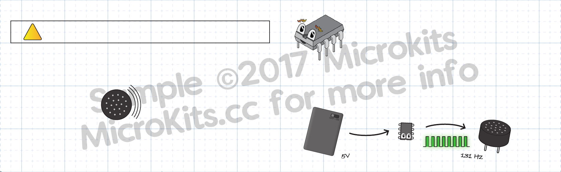
With this power, I create an electrical signal that I send to the speaker. When the
signal changes, the magnet inside the speaker moves. This creates sound that you can
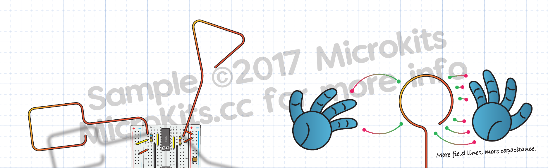
hear. I’m only playing a single note now, so let’s add parts to build a real theremin!
MICRO
OFF - ON
Power
Signal
131 Hz
5V
TICK
MICRO
♪
♫
♫
♪
♪
TICK
MICRO
♪
♫
♫
♪
♪

16 17
Sample ©2017 Microkits
MicroKits.cc for more info
□Turn power “OFF” while building the circuit.
□Place Tick in rows 1 to 7 and column E & F, with
eyes pointed down. Direction matters!
□Connect A7 to the “
-
” strip with an orange wire.
□Connect J1 to the “+”strip with an orange wire.
□Connect J5 to the “+”strip with an orange wire.
+-
+-
+-
+-
1
5
10
15
20
25
30
1
5
10
15
20
25
30
a b c d e f g h i j
a b c d e f g h i j
MICRO
104
TICK
Stage 2: Pitch Control
TICK
□Connect G3 to G7 with a yellow wire.
□Connect H6 to H14 with a gray wire.
□Find the resistor with the following bands: Yellow
Purple Orange. Place it in I3 and I6 (either
direction will work).
The colors show the value of the resistor.
This one is 47,000 Ohms.
+-
+-
+-
+-
1
5
10
15
20
25
30
1
5
10
15
20
25
30
a b c d e f g h i j
a b c d e f g h i j
MICRO
104
TICK

18 19
Sample ©2017 Microkits
MicroKits.cc for more info
+-
+-
+-
+-
1
5
10
15
20
25
30
1
5
10
15
20
25
30
a b c d e f g h i j
a b c d e f g h i j
MICRO
104
TICK
□Place one of the two long copper wires in J3.
The wire should stick straight up and away from
the board, but other than that you can bend
it however you want. This will act as our pitch
antenna.
This antenna is a
big capacitor!
Give your circuit one more check, and when you’re ready, turn
it “ON”! What happens when you reach toward the antenna? If
nothing changes and the note stays constant, turn “OFF” the power
and troubleshoot like before.
If the pitch increases as you approach, congratulations! Your theremin is working. You
can now create three octaves worth of notes just by waving your hand.
We’re not done yet, though. We still need to add the volume antenna to create a fully
functional theremin.
But before we do that, let’s learn a bit more about the circuit we just built!

20 21
Sample ©2017 Microkits
MicroKits.cc for more info
So how does a theremin work, anyway? It’s all about turning one kind of signal into
another kind of signal. First, your hand adds electric fields to the antenna. This adds
capacitance. Tick creates a high frequency signal based on this capacitance.
Then, I, Micro, read the signal from Tick. I do math to turn Tick’s high frequency
signal into a signal you can hear. Then, the speaker turns my signal into sound.
TICK
MICRO
♪
♫
♫
♪
♪
~500,000 Hz
0.001 nF
440 Hz
Capacitance
Signal
Sound
I bet you’re wondering how Tick turns capacitance into a signal. Tick
contains a timer circuit, a kind of clock. This clock is based on the
amount of time it takes to build up a tiny amount of charge. In this
case, the theremin antenna is what is building up the charge.
Moving your hand toward the antenna adds capacitance, and Tick needs extra time to
charge. The resistor you added also changes Tick’s frequency. The whole equation is:
Where R is resistance, C is capacitance, and F is output frequency. F is proportional to
the inverse of R and C. This just means that the more resistance and capacitance, the
lower the frequency.
f= 0.72/RxC

22 23
Sample ©2017 Microkits
MicroKits.cc for more info
□Turn power “OFF” while building the circuit.
□Connect A4 to the “+”strip using a yellow wire.
□Connect C5 to C13 using a gray wire.
□Connect D2 to D6 using a yellow wire.
□Place the resistor with Blue Grey Orange bands in
B2 and B5.
+-
+-
+-
+-
1
5
10
15
20
25
30
1
5
10
15
20
25
30
a b c d e f g h i j
a b c d e f g h i j
MICRO
104
TICK
68,000 Ohms
Stage 3: Volume Control
□Place the second long copper wire in A2. Bend
it up and away from the circuit board, and off
to the side. Make sure to keep this antenna
away from the pitch antenna. This is our volume
antenna.
+-
+-
+-
+-
1
5
10
15
20
25
30
1
5
10
15
20
25
30
a b c d e f g h i j
a b c d e f g h i j
MICRO
104
TICK

24 25
Sample ©2017 Microkits
MicroKits.cc for more info
Your theremin is now complete. Turn it “ON” and see if volume
decreases when you move your hand toward the second antenna. If
not, you know how to troubleshoot!
What did you learn from this project?
□How to connect different parts to build a circuit.
□What kind of parts are needed for a circuit and what they do.
□How to troubleshoot mistakes and check your work as you go.
□How electric fields and capacitance work, and are turned into electrical signals.
Playing the theremin is challenging, but here are some tips!
□Use your left hand to control the volume antenna, and your right for pitch.
□More surface area means more capacitance. Move your whole hand toward the
instrument and focus on the middle of the antenna, not the end.
□Bend the two antennas away from each other, so that they don’t interfere.
□Your theremin automatically adjusts to the environment. If you move the
antennas or the tuning seems wrong, just turn it off and back on again.
□Turn the battery holder “OFF” when not in use.

26 27
Sample ©2017 Microkits
MicroKits.cc for more info
Try Different
Antenna Shapes
Congratulations on building your theremin! But this is only the start. Now you can learn
more about electronics, experiment with music, and investigate physics. What will you
do next?
Build a Box
to Hold the
Circuit
Find Out More
at MicroKits.cc!
Test the
Capacitance of
Different Things
Impress Your
Friends with
Science
Research the
History of the
Theremin
Learn to
Play a Melody
Build More
Electronic Kits
104
TICK
MICRO
See Ya
Later!

Antenna: a conductor that can send or receive electromagnetic waves •Capacitance:
the ability to hold an electric charge •Circuit: a path for electrical current to flow,
made up of different electrical parts •Frequency: the number of times a wave
repeats in a unit time • Integrated Circuit: also called a chip, a miniaturized circuit
created on a thin semiconductor wafer •Pitch: the frequency of a sound •Resistance:
the ability to resist the flow of electrical current •Timer: an integrated circuit
which changed frequency based on resistance and capacitance •Troubleshooting:
finding and solving problems in a system •Volume: the loudness of a sound
⚠ WARNING
• Small parts. DO NOT allow children under 3 years old to play with or near this product.
• NEVER connect any part of the kit or circuit to any AC electrical outlet.
• Discontinue use of any kits that malfunction, become damaged or broken.
• Components are subject to damage by static electricity. Handle with care.
• Keep conductive materials (such as paper clips, aluminum foil, etc.) away from the circuit and battery.
• Always turn OFF the battery pack when not in use, when left unattended, or when disconnected from the rest of the circuit.
• Incorrect connections can cause damage or overheating to system or batteries. Always ensure proper connections before turning on.
• Never use the kit in or near any liquid, or in any extreme environments such as extreme hot or cold, high humidity, or sand.
Safety First!
©2017 MicroKits
Other HACKADAY Science Education Product manuals
Popular Science Education Product manuals by other brands

KOKEN
KOKEN LM-104 instruction manual

Eastern Voltage Research
Eastern Voltage Research microBrute DRSSTC Tesla Coil KiT instruction manual

InVento
InVento Star Coaster instruction manual

Life form
Life form LF03611U instruction manual

Life form
Life form LF01027U instruction manual

KOKEN
KOKEN LM-060 instruction manual