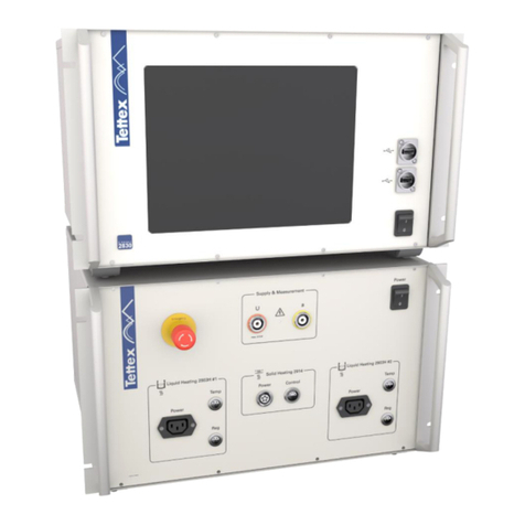
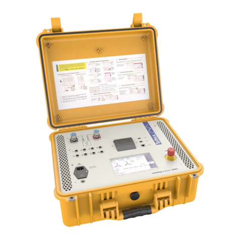
Haefely 2823 User manual

2823 &
2823-REF
High-Precision C, L & tan δ
Measuring Bridge
Quick Start Guide
4844145 | Version 0.3

2 Safety
Title 2823 & 2823-REF Quick Start Guide
Date 05-2017
Authors SG
Layout SG
Part number 4844145
Revision History
Date Version Author Remarks
24.05.17 0.1 SG Initial release of the document
28.06.17 0.2 SG Installation to be run as administrator and small changes
30.03.20 0.3 SG Logos Update

3 Safety
1. Safety
General
The “Operating Instructions” must be read and fully understood before operating this instrument. All tests
should be performed with the device under test completely disconnected from its power systems and fully
de-energized. This means all bus connections to and from the device under test must be removed.
Remember: Safety - First, Last, Always !
This quick start guide is not a replacement of the instrument manual.
This equipment contains exposed terminals carrying hazardous voltages. There are no
user serviceable components in the unit. All repairs and upgrades that require the unit to
be opened must be referred to HAEFELY TEST AG or one of their nominated agents.
This equipment must be operated only by trained and competent personnel who are aware
of the dangers and hazards involved in testing transformers and other HV apparatus.
HAEFELY TEST AG accepts no liability for loss, damage, injury or death caused by the
incorrect or unsafe operation of this instrument.
Grounding
The instrument must always be connected to a grounded power outlet (i.e. a safety earth)
before connecting to the to the high-voltage test system.
It must never be operated in a non-grounded configuration as this may result in electrical
shock to the user or damage to the instrument.
Always Use grounding rods when entering the high-voltage test area.
Be aware that when disconnecting the measuring input cable from the equipment you are
virtually “touching” the high-voltage divider output which might be under high voltage.
Always disconnect a measuring cable on the divider side FIRST!
Mains Connection
Connection of the system to a supply voltage outside the specified operating range will
result in damage to the system along with the risk of injury and fire.
Essential Safety Recommendations
Before connecting the instrument ensure that the HV capacitor is completely de-energized,
isolated from the load and grounded. Every terminal shall be checked and verified before
connecting the instrument. Ground connections may remain in place.

4 Foreword
2. Foreword
Welcome as a new user of the “2823 High-Precision C, L & tan δMeasuring Bridge”. Thank you for
placing your confidence in our product.
With the purchase of this measuring instrument you have opted for all the advantages that have built a world-
wide reputation for a Haefely Instrument: robustness, performance and quality is assured. As a result this
instrument provides a solution which achieves the optimal combination of traditional know-how and leading
edge technology.
This Quick Start Guide is designed for customers who already have experience with high voltage abd this kind
of equipment. For extended help a complete manual with additional information is available as electronic
document.
If you find a mistake or inconsistency in the Quick Start Guide please feel free to inform our Customer Support
department with your corrections so that other users may benefit.
3. Installation
2823 Back panel connections
Figure 3-1
1 Equipment Identification and Serial Number
2 CxInput Test Object
3 CNInput Nominal Capacitor
4 Ground
5 Low potential from High Voltage (V)
6 UST – GST Mode bridge connection
7 Optical Connection to Media Box
8 Main Switch
9 Mains Input Socket
10 Power indicator LED

5 Installation
2823 Media converter connections
Figure 3-2
1 Ethernet connection (optional data transfer)
2 USB connection to PC (power and data transfer to computer)
3 Power indicator LED
4 Link indicator LED (optical connection to 2823 established)
5 Activity indicator LED (data transfer)
6 Optical connector for fiber optic link to 2823 instrument
Instrument Setup
Instrument Location
To take benefit of the galvanic isolation and increase the operator safety, it is recommended to install
the 2823 inside the High voltage laboratory, either fixed in a plate in the button of the nominal
capacitor or at any other location inside the high voltage laboratory.
System connection Overview

6 Installation
Instrument connections
Connections to the instrument should be done as in the Figure 3-3. Main attention to connect the HV
ground first.
Lemo type connectors for CNand CXhave a rotary screw at the end to be locked/unlocked. Make sure
the Lemo connector is locked after plugging in.
Before connecting the instrument ensure that the HV capacitor is completely de-
energized, isolated from the load and grounded. Every terminal shall be checked
and verified before connecting the instrument.
Figure 3-3 Instrument connection
1 Connect to Ground (GND) with delivered or bigger cable / cupper band.
2 Connect the V(supply) point to the low point of the High Voltage power supply
3 Connect the Nominal capacitor measurement Cable to CNInput
4 Connect the test Object Measuring Cable to CXInput
5 Connect the Communications Cable to the communications Input
6 Connect the Mains cable
Fiber optic cable is connected as described in figure Figure 3-4
Figure 3-4 Fiber optic connection

7 Installation
UST and GST Standard Measuring Circuits
Capacitance and tan delta (power factor) can be measured on ungrounded test objects (UST) or
grounded test objects (GST). The common procedure in the HV laboratory is to measure as
ungrounded test object. Complete information about both test circuits and when to use them is
included in the instrument manual.
Only when test object is physically connected to ground and is not possible to disconnect, the GST
mode should be selected, for all the rest the UST mode should be used.
UST Mode
Test Object ungrounded – Power splay to ground
GST Mode – V and Ground separated
Test Object Grounded – Power supply to V
Figure 3-5 UST and GST modes
The selection between modes is done with the manual bridge in the instrument back panel.
UST Mode Selected
V and Ground Connected
GST Mode selected
V and Ground Isolated
Figure 3-6 UST and GST Selection in the 2823
Electrical connection between the V(supply) point from the back of the 2823 and the
low voltage point of the high voltage power supply is required. Missing this
connection can end in instrument damages.

8 Installation
V Connection
This 2823 is able to measure capacitances with highest accuracy to determine trending analysis of
insulating materials. Depending on the measuring circuit it could exist other capacitances (ex. stray
capacitances) measured together with the DUT that can influence the measured values significantly.
These unwanted capacitances have to be eliminated from the measuring circuit. To do so connect
them to the V(Common) point.
In general all capacitances connected to the V Point are bypassed.
Ground connections
Ground connections are of vital importance in a High Voltage laboratory, as high currents and
therefore overvoltages can arise in case of a failure in the test object. These overvoltages can be
dangerous for the personal, and can damage measuring instruments, computers or electronic devices
connected in the control room.
Ground connections in the High Voltage laboratory must be done with low
inductance cable (preferred cupper band) and remain as short as possible. In
addition all elements must be connected to a central ground point in a star
configuration.
Keep short and low inductive ground connections increases the measurement
accuracy and reduce the risk of instrument/computers failures.

9 Installation
Media Converter Setup
Media Box connections
The connection of the Fiber optic cable and USB cable to the media Box is shown in the figure Figure
3-7.
Figure 3-7 Media converter connection
Computer connection
The USB cable from the media converter should be connected to any available USB port with power
supply in the computer.
Figure 3-8 Computer connection

10 Installation
Software Installation
Installing the software
Software is built to run in any computer with Windows 10 or Windows 7 installed in English
language. Installation of the software requires administration rights on the computer.
Computer measuring software is delivered in a memory stick into a
metallic box. Installing the software is similar to any installation of a
Windows based application.
1. Plug the memory stick in a free USB port in the Computer
used as control unit for the 2823.
2. Open the USB drive (drive name will depend on the computer,
normally E:) and double click on the setup file.
Installation must be run as administrator for all drivers to be
installed correctly.
3. Click Next to start the Software installation
4. “Automatically start on login”, if selected each time the
computer is started, 2823 software will be automatically
launched, select the preferred option. Normally deactivated
5. Select “Launch PCap Installation” and “Launch USB LAN
Driver” and click Finish
2823 software requires the installation of the WinPcap tool
for network access in Windows. The installation starts
automatically after the installation of the 2823 software.
6. Select “Automatically start the WinPCap” at boot time
Once software is installed, a new icon and application group will
appears in the desktop and start menu respectively called 2823.

11 Installation
2823-Computer Communications settings
The media box act as a USB to Ethernet adaptor, To guarantee continuous communication and avoid
conflicts with other devices, the necessary Ethernet settings have to be introduced manually first time
the media box is connected to the computer.
Ethernet setting are linked to the physical USB port where the media converter is plugged.
If media converter is connected to a different USB port, the manual configuration described
on this chapter has to be repeated..
It is recommend to use always the same USB port to connect the media converter to the
computer
The driver for the media box is installed together with the 2823 software. Therefore no manual
installation required.
Once the media converter is plugged for first time to an empty USB port, an additional Ethernet port
should be available. Following steps describe the procedure to configure the communications.
1. Go to the Network Connections by clicking with the right
button on the windows menu in the button left side of
the computer
2. Check that a new Ethernet adaptor is available.
if there are more than one and not sure which one is the media
converter, unplug and plug again the media converter. The
corresponding Ethernet adaptor should disappear and appear
again.
3. Right click on the corresponding Ethernet adaptor.
Select Properties in the button of the menu.

12 Running the 2823 first time
4. Select “Internet Protocol Version 4 (TCP/Ipv4)” and click
the properties button
5. Configure the protocol as following
a. Select “Use the following IP Address”
b. Introduce 192.168.0.50 as IP address
c. Introduce 255.255.255.0 as Subnet Mask
d. Let the default gateaway empty
If the Address 192.168.0.50 is already use, increase the last
number to 51.
6. Click OK button and close any open window
4. Running the 2823 first time
Configuring the 2823 software
Starting the software
To run the software just double click in the corresponding Icon in the desktop. The start screen will
arise for some seconds.
Instrument will do some self-checking every time software
starts. Firmware and software versions are shown in the
right side of the starting screen.
If communication with the 2823 fails, “not connected” error
will arise in the upper band and measurements will not be
possible. Possible reasons are.
1. 2823 has not been switched on, make sure the
mains switched is in I position and the green led
beside is on.

13 Running the 2823 first time
2. Communication cable between 2823 and media
converter not properly connected.
3. Incorrect Ethernet communication settings, double
check the communication settings following
carefully the instructions in the “computer
communications settings” chapter
The main options of the software are located on the right
side of the screen, including Setup, Manual, Sequence and
Analysis.
•Setup: Basic and advance instrument settings
•Manual: Manual measurement
•Sequence: Sequence measurement
•Analysis: create charts, analyse the results
Configuring the Measuring circuit
To guarantee the full instrument accuracy, some parameters have to be manually introduced first time
in the software. These parameters are stored and don’t have to be introduced again.
Nominal capacitor capacitance introduction
1. Go to Setup -> settings, in the “Standard Capacitor
Cn” group Introduce the nominal capacitor
capacitance in the value textbox.
2. The “DF(tand) @ 50Hz” should remain at 0.0 (see
manual for additional information)
Measuring cable length introduction
1. In Measuring Cables -> Length introduce the
length of the measuring cable between test object
and 2823
2. In “Standard Capacitor Cn->Cable to Cn” introduce
the length of the cable between nominal capacitor
and test object
1
2
1

14 Running the 2823 first time
Performing a manual measurement
DUT Data introduction
DUT data
1. Go to Setup -> DUT Info and Introduce the desired
information, no field is mandatory.
Tan δ(power factor) varies with the temperature for some
test objects. The 2823 can automatically compensate this
variation and refers the values at reference temperature.
1. In Ambient->Temperature introduce the ambient
temperature
2. In Device under test DUT insulation->temperature
introduce the reference temperature
3. Select the test object type
4. The temperature correction table will arise in the
button
Measuring
DUT data
1. Go to Manual
2. Select the parameter to be shown on each
indicator by clicking in the small triangle after the
name
1
2
3
4
1
2

15 Additional information
1. Increase the voltage to the desired level(all safety
regulations have to be fulfilled before increasing
the voltage)
2. Once voltage is stable, wait until digits change
from dark green to light green (light green means
value is stable and therefore can be recorded)
not stable stable
3. Once values are stable Click “Record” button to
add a value to the table
4. Repeat the above steps for every required
measuring point
Measurements can be saved to the hard disk, and
reports can be easily created. To do so select “File
Manager” in the button right side of the screen
1. To save the measurement, select save button
2. To create a report, select the report button
5. Additional information
Latest software and manuals
Complete instrument manual can be found as a PDF document in the memory stick, in the
manual folder.
New Software, as well as updated instrument manuals and other information about the device can be
downloaded from
http://update.haefely.com/2823/
Support
Please check the manual for further information about the instrument use or troubleshooting. If persistent
problems or faulty operation should occur then please contact the Customer Support Department of HAEFELY
TEST AG or your local agent. The Customer Support Department can be reached at the following postal
address:
HAEFELY TEST AG
Customer Service - Tettex
Birsstrasse 300
CH-4052 Basel
Switzerland
1

16 Additional information
This manual suits for next models
1
Table of contents
Other Haefely Measuring Instrument manuals