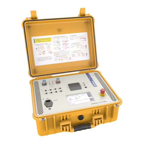
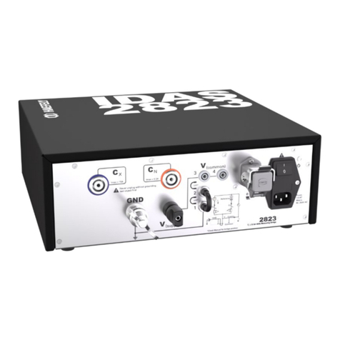
Haefely 2830 User manual

2830/2831
Precision Liquid and Solid
Dielectric Analyzer
User Manual
4843477-M | Version 3.0

II
Revision History
Version
Date
Author
Remarks
2.0
2013-12
MB
2nd release
3.0
2021-07
SM
3rd release

III
WARNING: Before taking the equipment into operation, be sure to read and
understand fully the operating manual and instructions.
HAEFELY has a policy of continuing improvement on all their products. The design of this
equipment will be subject to review and modification over its life. There may be small
discrepancies between the manual and the operation of the equipment, particularly where
software has been upgraded in the field.
Although all efforts are made to ensure that there are no errors in the manuals, HAEFELY accepts
no responsibility for damage or loss that may result from errors within this manual. We retain the
right to modify the functionality, specification or operation of the equipment without prior notice.
©All rights reserved. No section of this manual may be reproduced in any form, mechanical or
electronic without the prior written permission of HAEFELY.
2021, HAEFELY AG, a member of the PFIFFNER group

IV
Introduction
Contents
1Introduction 1
1.1 General ................................................................................................................1
1.2 Scope of Supply...................................................................................................1
1.3 Accessories and Options.....................................................................................2
1.4 Hardware .............................................................................................................2
1.5 Software...............................................................................................................2
2Glossary of Terms and Abbreviations 3
3Safety 4
3.1 General ................................................................................................................4
3.1.1 Five basic safety regulations ...................................................................5
3.1.2 Ground Connections................................................................................6
3.1.3 Test Area .................................................................................................6
3.1.4 Mains Connection....................................................................................6
3.1.5 Cleaning and Maintenance......................................................................6
3.1.6 Health Notes............................................................................................7
3.2 Training and Education........................................................................................7
4Technical Data 8
4.1 Specifications.......................................................................................................8
5Theory 10
5.1 Dissipation Factor tanδ ......................................................................................10
5.2 Parallel and Series Equivalent Circuits..............................................................11
5.3 The difference between Power Factor and Dissipation Factor..........................12
5.4 Relative Permittivity ...........................................................................................12
5.5 DC Resistivity.....................................................................................................15
5.6 Test Instruments................................................................................................17
5.7 Evaluation of Test Results.................................................................................18
5.8 Other Test Methods...........................................................................................19
6Device Functions 20
6.1 System Overview...............................................................................................20
6.1.1 C & tan δ ................................................................................................20
6.1.2 DC Resistivity.........................................................................................21
6.1.3 Vcommon point and Guarding...............................................................22
6.2 Standard test circuits .........................................................................................22

Introduction
V
7Device Operations 24
7.1 Touch Screen .................................................................................................... 24
7.2 Front Panel 2830............................................................................................... 25
7.3 Rear Panel 2830................................................................................................ 25
7.4 Front Panel 2831............................................................................................... 27
7.5 Rear Panel 2831................................................................................................ 28
8Assembling and Installation Guide 29
8.1 Mounting of 2830 and 2831............................................................................... 29
8.2 Inter-wiring of 2830 and 2831............................................................................ 29
9Software 30
9.1 General.............................................................................................................. 30
9.1.1 Start-up.................................................................................................. 30
9.1.2 Basic Window structure......................................................................... 32
9.1.3 Heater & Cell Status.............................................................................. 33
9.1.4 Basic Buttons......................................................................................... 37
9.1.5 Title Bar ................................................................................................. 39
9.1.6 Alarm Messages.................................................................................... 40
9.1.7 Error Messages ..................................................................................... 42
9.1.8 Informative Messages ........................................................................... 43
9.2 File Manager...................................................................................................... 44
9.2.1 File Selector Dialog ............................................................................... 45
9.2.2 Report.................................................................................................... 47
9.3 Setup ................................................................................................................. 48
9.3.1 DUT Info ................................................................................................ 49
9.3.2 Settings.................................................................................................. 51
9.3.3 Heating cell(s)........................................................................................ 53
9.3.4 Options .................................................................................................. 54
9.3.5 Auxiliary................................................................................................. 57
9.3.6 About Screen......................................................................................... 57
9.4 C tan δ ............................................................................................................... 58
9.4.1 Signal Analysis ...................................................................................... 63
9.5 DC Resistivity .................................................................................................... 66
9.5.1 Test cell shorting ................................................................................... 70
9.6 Sequence........................................................................................................... 72
9.6.1 Run a Sequence.................................................................................... 72
9.6.2 Run two sequences simultaneously...................................................... 77
9.6.3 Program a sequence............................................................................. 78

VI
Introduction
9.6.4 Sequence commands............................................................................82
10 Accessories 98
10.1 Accessories and Options...................................................................................98
11 Care and Maintenance 99
11.1 Care and Maintenance ......................................................................................99
11.2 Cleaning the Instrument.....................................................................................99
11.3 Instrument Calibration........................................................................................99
11.4 Changing Fuses...............................................................................................100
12 Instrument Storage 101
12.1 Instrument storage...........................................................................................101
13 Packing and Transport 102
13.1 Packing and Transport.....................................................................................102
14 Recycling 103
14.1 Recycling .........................................................................................................103
15 Troubleshooting 104
15.1 Windows Recovery..........................................................................................104
15.2 Software Updates 2830 ...................................................................................105
15.3 FAQ..................................................................................................................105
15.4 Error Assistance...............................................................................................106
15.4.1 ComError ...........................................................................................106
16 Service, Maintenance and Contact Information 107
16.1 Warranty Information .......................................................................................107
16.1.1 Guarantee period...............................................................................107
16.1.2 Liability for defects in material, design and workmanship .................107
16.2 Maintenance ....................................................................................................108
16.2.1 Cleaning the Instrument.....................................................................108
16.3 Spare Parts......................................................................................................108
16.4 Repair (RMA)...................................................................................................108
16.5 Calibration........................................................................................................109
16.6 Support ............................................................................................................110
16.7 Addresses / Webpage .....................................................................................111
16.7.1 Europe Office.....................................................................................111
16.7.2 China Office.......................................................................................111
16.7.3 Webpage............................................................................................111
16.7.4 Remote Support.................................................................................112

VIII
Introduction

Introduction
1
1Introduction
1.1 General
The Precision Oil and Solid Dielectric Analysing System is designed for measurement of liquid
and solid insulating materials with a very low dielectric losses (Dissipation Factor and Power
Factor) of high voltage insulating material (e.g. Transformer Oil).
The instrument works on the principle of a combined bridge-vector-meter and is capable of
analysing capacitive and dissipation factor (tan ) as well as DC-Resistivity with outstanding
accuracy and stability.
The Graphical User Interface of the instrument is highly intuitive, focussed on convenience with
built-in useful programs (e.g. pre-programmed procedures according the standards) and uses a
large colour touch screen as the input device. The operator can choose between manual or
automatic modes. While the manual mode provides quick measurements, the automatic test
mode supports complete automated test sequences according the standards.
1.2 Scope of Supply
The following items are supplied:
Qty
Description
1
Precision Oil and Solid Analyzer 2830/2831
1
Inter-Wiring cable set
2
Mains cable 10A and 16A (country specific)
1
Operating instruction
1
Test certificate
Test cables corresponding to order
On receipt of the unit check that all items have been delivered. In the event
of missing or damaged parts please contact your local sales representative
stating the serial number, the type of the equipment and the sales order
number.

2
Introduction
1.3 Accessories and Options
Optional (for details see product data sheet on www.haefely.com)
For details on optional accessories (Oil Test Cell 2903 and Solid Test Cell 2914) and test cable
sets see product brochure and/or contact the Tettex Sales.
Qty
Description
1
Liquid test cell- 2903
1
Solid test cell- 2914
Note: If you use existing oil test cells 2903 or solid test cells 2914 with the 2830/2831 you need
a new measuring cable set.
On receipt of the unit check that all items have been delivered. In the event
of missing or damaged parts please contact your local sales representative
stating the serial number, the type of the equipment and the sales order
number.
1.4 Hardware
This high precision measuring instrument (double vector meter) is fully automatically balanced by
the built-in PC and the measurement values are calculated and displayed. Thirteen parameters
can be measured respectively calculated. The instrument, as a vector meter bridge including the
heating regulation, DC and AC power supply, DC resistance measurement.
1.5 Software
Advanced software functionalities such as pre-programmed test sequences according standards
and graphical visualization of measured data, etc. make this instrument a powerful tool for
analysis of high voltage insulating material. The clear structured user interface makes the settings
and the sequence programming fast and easy.

Glossary of Terms and Abbreviations
3
2Glossary of Terms and
Abbreviations
In the manual, the following conventions are used:
Indicates a hint or a matter of note - if it refers to a sequence of operations,
failure to follow the instructions may result in measurement errors.
Indicates hazards. There is a risk of equipment damage or personal injury or
death. Carefully read and follow the instructions. Be sure to follow any
safety instructions given in addition to those for the site at which tests are
being performed.
Wherever possible the corresponding standard (IEC, ANSI) definitions are used. The following
abbreviations and definitions are used in this manual:
Abbreviation
Meaning
SI
Système International d’unités (International System of Units)
IEC
International Electrotechnical Commission
ASTM
American Society for Testing and Materials
BS
British Standards
VDE
Verband der Elektrotechnink
SAC
Standardization Administration of China
CN
Standard capacitor (measurement reference; built-in the 2831)
CX
Test object capacitance (e.g. transformer oil, oil paper, solid material etc.)
HV
High voltage
cos
Power factor
PF
Power factor

4
Safety
tan
Dissipation factor
DF
Dissipation factor
DUT
Device under test
ppm
Parts per million
0
Vacuum Permittivity
r
Relative Permittivity
3Safety
3.1 General
Safety is the responsibility of the user. Always operate the equipment in
accordance with the instructions, always paying full attention to local safety
practices and procedures.
This equipment must be operated only by trained and competent personnel
who are aware of the dangers and hazards involved in high-voltage-testing
and other HV-apparatus. HAEFELY accepts no liability for loss, damage,
injury or death caused by the incorrect or unsafe operation of this
equipment.
General Safety is the most important aspect when working on or around high voltage electrical
equipment. Personnel whose working responsibilities involve testing and maintenance of the
various types of high voltage equipment must have understood the safety rules in the manual and
the associated safety practices specified by their company, national and regional regulations.
Company, national or regional regulations must be fulfilled beyond HAEFELY recommendations.
This system produces hazardous voltages that can causes in shocks, burns or death. It is the
responsibility of the personnel to ensure that the system is operated in a safe manner.
HAEFELY and its sales partners refuse to accept any responsibility for consequential or direct
damage to persons and/ or goods due to none observance of instructions contained herein or
due to incorrect use of the equipment.

Safety
5
3.1.1 Five basic safety regulations
At any entering or working with high voltage systems always consider the five basic safety
regulations:
1) Disconnect mains!
2) Prevent reconnection!
3) Test for absence of harmful voltages!
4) Ground and short circuit!
5) Cover or close off nearby live parts!
After high voltage tests have been performed the first thing during entering high voltage parts are
should be grounded. A manual ground rod must be used. In some configurations a recurring
voltage on capacitor can appear also after earthing. In these cases, a second ground rod can
help to reduce that risk.
Always use grounding rods when entering a high-voltage-test area.

6
Safety
3.1.2 Ground Connections
The ground connections between the different components of the system must be made without
forming loops (copper-foil or copper-braid) and in best case in star connection. The ground
connection should be low inductive and able to carry the continuous short-circuit current.
3.1.3 Test Area
Never operate the system in an explosive environment or where flammable
gases or fumes are exciting.
A good test area can enter a separate grounding. This ensures that no disturbances from
surrounding machines enter the test field. It is necessary for the test field to have a lower
grounding resistance than the surrounding building.
The test area must be equipped with an adequate security circuit. Also, an appropriate shielding
and protection against the high voltage parts and terminals must be installed.
In the test area minimum one manual ground rod has to be installed. It should be placed nearby
the entrance of the test area.
3.1.4 Mains Connection
Connection of the system to a supply voltage outside the specified
operating range will result in damage to the system along with the risk of
injury and fire.
3.1.5 Cleaning and Maintenance
For cleaning and maintenance work it has to be ensured that all parts are
disconnected from any mains supply. Always use grounding rods when
entering the test area. Use the emergency stop.
Never open a cover or a case before having disconnected the power supply. Always pay full
attention to the safety rules (especial on hazardous voltages).
Unauthorized opening of the equipment may damage the system or the EMC protection. It may
also cause the equipment to be no longer compliant with the relevant standards and susceptibility
requirements. If the equipment has been opened, the calibration can be rendered invalid.
HAEFELY and its sales partners accept no liability for loss, damage, injury or death caused by
the incorrect or unsafe operation of this instrument.

Safety
7
3.1.6 Health Notes
This system produces hazardous voltages that can cause shocks, burns or death.
During operation high electric and magnetic fields can occur. The fields can affect to your health.
Different measures can help here to reduce the risk (example: shielding against the fields,
increase of the distance to the high voltage system, duration of the test, lower voltage/ current
levels).
Some system configurations produce loud or monotonous noises. Different measures can help
here to reduce the noise (example: acoustic shielding, ear protection, increase of the distance to
the high voltage system, duration of the test, lower voltage/ current levels).
People with heart pacemakers should not be in the vicinity of the system during operation.
3.2 Training and Education
The customer is responsible that the persons, which work with the system, are trained and
educated in operation and safety for that. Only trained persons are allowed to work with the
system. The training has to be repeated in regular intervals. The training has to be documented.
The safety is the responsible of the operators. When working on high voltage system, at least two
persons must always be present, one of them bears responsibility for the system and the
performed tests. The second person is the role of the safety observer.
Non-test related persons who are working in proximity to the area where testing is performed
must be informed. Consistent visual and verbal signals should be agreed and followed.
Operator:
The person who makes the test, connections and operates the system. He must be able to have
a clear view of the device under test and the area where the test is performed.
Safety Observer:
The person who is responsible for observing the performance of the test, seeing any safety hazard
and giving warning to people.

8
Technical Data
4Technical Data
4.1 Specifications
Measurement 2830
Range
Max.
Resolution
Accuracy
Dissipation Factor (tan
) 1
0 .. 100
1 x 10⁻⁵
0.5 % rdg 1 x 10⁻⁵
Capacitance 2
10 pF
0.001 pF
0.2 % rdg 0.01 pF
Relative Permittivity r
1 .. 30
1 x 10⁻³
Resistance
120 kΩ .. 5 TΩ 3
1 kΩ
< 1 TΩ 5 % rdg+ 3
digits
≥ 1 TΩ 15 % rdg+ 3
digits
Resistivity (Liquid) 4
900 kΩm .. 27 TΩm 5
Resistivity (Solid) 6
2.4 MΩm .. 80 TΩm 7
Test Current @ Input
Cx
10 uA .. 10 mA
0.01 uA
0.1 % rdg 0.1 uA
Test Current @ Input
Cn
10 uA .. 10 mA
0.01 uA
0.1 % rdg 0.1 uA
Test Frequency
15 Hz .. 100 Hz
0.01 Hz
0.1 % rdg 0.1 Hz
Power Supply’s 2831
Range
Max.
Resolution
Accuracy
AC Test voltage
40 V .. 2.5 kV
1 V
0.3 % rdg 1 V
AC Frequency
40 Hz .. 65 Hz
0.1 Hz
AC Current max.
5 mA
DC Test Voltage
250 V .. 2.5 kV
25 V
+ 10 % rdg 20 V
Heater
Heating Temperature
Ambient –200 C
0.1 C
0.5 C
Internal Standard
capacitor
Value
Accuracy
Dissipation Factor (tan
)
1 x 10⁻⁵
2 x 10⁻⁵
Capacitance
1 nF 5 % @ 25 °C
20 ppm/°C
Additional
Specifications
Preprogrammed
Standards
IEC 60247:2004; ASTM D924-08; ASTM D1169:2002; VDE 0380-
2:2005; BS 5737:1979; SAC GBT 5654:2007
Display
12” TFT, 800x600, integrated Touch-Screen

Technical Data
9
Operating System
Windows Embedded 7
Interfaces
3 x USB
Data Format
XML, CSV
Operating Temperature
10 .. 40 °C
Storage Temperature
-20 .. 70 °C
Humidity
10 .. 60 % r.h. non-condensing
Protection classes,
Standards
IP20, IEC 61010, CE mark,
General IEC 61326-1, IEC 61000-4-X, 61000-3-X, EN 55011,
ANSI/IEEE C37.90
Safety Specification
VDE 0411/part 1a , IEC/EN 61010-1:2002
Supply 2830
90 .. 264 VAC, 100 VA, 50 / 60 Hz
Supply 2831
90 .. 264 VAC, max.1.7 kVA, 50 / 60 Hz
Weight
21 kg (2830), 19 kg (2831)
W x H x D
2 pcs 48 x 27 x 44 cm (19” x 10.6” x 17.3”)
1 Accuracy values @ 50/60Hz
2 Range limit is given by test current and voltage
3 @ 2.5 kV (Rmax = 2 GΩx Utest [V])
4 Resistivity range is given by the resistance range multiplied with the cell factor of the test cell (2903 = 0.113 x Cair [in pF])
5 Typical range (calculated with Cair = 60.0 pF of 2903 and 2 kV test voltage)
6 Resistivity range is given by the resistance range multiplied with the ratio: surface area of the measurement electrode / distance between
the HV and the measurement electrode (2914 = 0.002 m2 / distance in m)
7 Typical range (calculated with a distance of 0.1 mm between the electrodes and 2 kV test voltage)

10
Theory
5Theory
5.1 Dissipation Factor tanδ
To specify the insulation loss factor, the test object must be considered in the test arrangement as
a capacitor. Consider the liquid test cell and solid test cell. Are constructed from metal and
insulation, and therefore possess associated capacitive properties. Every test cell consists of two
electrodes: a high voltage and a guarded measuring electrode. The capacitance of the insulating
material between the two electrodes will be measured. The figure shows the components that
comprise a capacitance and the diagram for a simple disc capacitor.
Disc Capacitor
dA
C
=
where:
A electrode face
d distance between the electrodes
C capacitance
0dielectric constant of air (0=8,8542 x 10⁻¹² F/m)
rrelative dielectric constant dependent upon
material
= 0• r, dielectric constant
In an ideal capacitor the resistance of the insulation material (dielectric) is infinitely large. That
means that, when an AC voltage is applied, the current leads the voltage by exactly 90° as it flows
as pure current.
After further consideration it must be realized that every insulation material contains single free
electrons that show little loss under DC conditions with P= U2/R. Under AC a behaviour called
dielectric hysteresis loss occurs which is analogous to hysteresis loss in iron.
As losses therefore occur in every insulation material, an equivalent diagram of a real capacitance
can be constructed as follows:

Theory
11
Parallel equivalent diagram of a loss capacitance with vector
diagram
Loss factor (Dissipation Factor)
RCR
X
I
IP C
C
R
====
1
Q
tan
Power Factor
δ
tan2
1
tan
cos +
====
S
P
I
I
PF R
Q Reactive Powre
S Apparent Power
P Real Power
UTest applied test voltage
ICcurrent through capacitance
IRcurrent through resistance (insulating material)
I IC+ IR
C ideal capacitance
R ideal resistance
Because P = Q • tan , the losses which are proportional to tan , will usually be given as a value
of tan to express the quality of an insulation material. Therefore the angle is described as loss
angle and tan as loss factor.
5.2 Parallel and Series Equivalent Circuits
The measuring bridge measures and displays both - the parallel and/or series equivalent circuit
values.
The following formulas describe the calculation of the value conversion parallel –series :
Parallel equivalent circuit
Parallel Equivalent
Circuit Cp-Rp
Rp Cp
=
1
tan * *
* measured values

12
Theory
Series equivalent circuit
Series Equivalent
Circuit Cs-Rs
Cs Cp= +* ( tan *)12
Rs Rp= +
tan *
tan *
2
2
1
* measured values
5.3 The difference between Power Factor
and Dissipation Factor
While “Dissipation Factor”, tan is used in Europe to describe dielectric losses, the calculation
used in the United States is “Power Factor”, cos .
The statistical data that have been collected in North America have been calculated using the loss
factor cos (Power Factor) to specify the power losses in the insulation. Because the angles are
complimentary it is unimportant whether tan or cos is used as with very small values tan
0.5% the difference is negligible. However the conversion formulas are:
2
tan1
tan
+
=PF
2
1
tan PF
PF
−
=
5.4 Relative Permittivity
The linear permittivity of a material is usually given relative to ε0the permittivity of free space
(vacuum permittivity), as a relative permittivity r(also called the dielectric constant). In a
anisotropic material, the relative permittivity maybe a tensor, causing birefringence. The actual
permittivity is then calculated by multiplying the relative permittivity by 0.
0
=r
to solve equations to rthe below formula results.
0
=r
This manual suits for next models
1
Table of contents
Other Haefely Measuring Instrument manuals
Popular Measuring Instrument manuals by other brands

Decagon
Decagon DualHead Infiltrometer Operator's manual

Extech Instruments
Extech Instruments EX845 user guide

GOK
GOK SmartBox 4 LAN Assembly and operating manual

Hanna Instruments
Hanna Instruments HI 93705 instruction manual

PCB Piezotronics
PCB Piezotronics INI SENSORS 683A100001 Installation and operating manual

Schmidt
Schmidt SS 20.515 Instructions for use