HAEHNE Elektronische Messgeräte GmbH · Heinrich-Hertz-Str. 29 · D-40699 Erkrath Germany · Telefon 0211/9 25 91-0 · Fax 0211/9 25 91-20
HAEHNE
DMA2
DMA2 TI EN 09_16.indd Technical modication reserved
Adjustment instructions
- Apply power and select lter type (ltered/unltered), only option C and N.
- Allow 15 min warm-up time.
- After the sensors are completely mounted remove all material exerting an
external force, except the forces acting under normal conditions. In case of web
tension sensors this is the measuring roll without web, e. g. plastic,
lm, paper...
- Perform zero adjust.
- Apply force or weight of approximately 70 to 110 % of nominal value (as availab-
le). Adjust to corresponding value on the display and store.
- Remove force or weight and perform zero adjust if necessary.
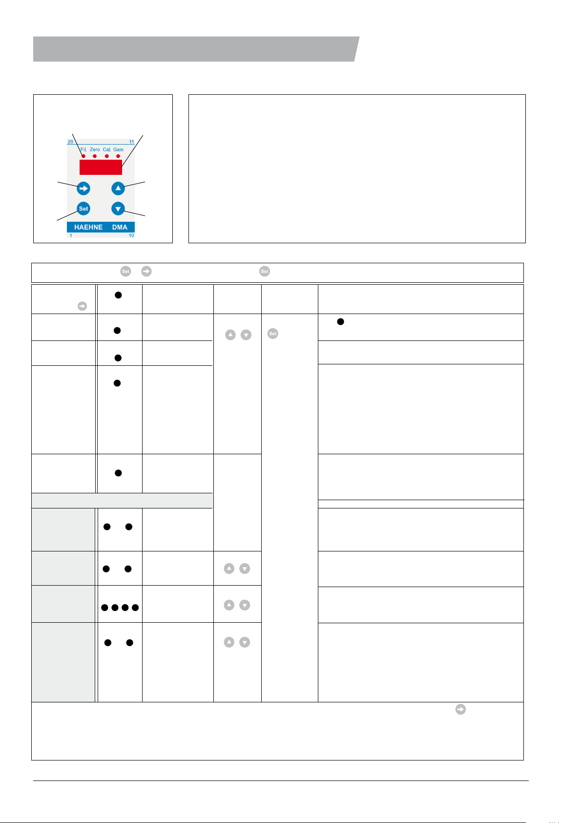
Display and operating elements
DOWN
UP
SET
MENU
LED DISPLAY
1. Select menu 2. Ad- 3. Storing
point with LED blinks Display justing Note
Filter behaviour Fil. dir / Fil Fil. Is always ON if current output
current output (direct/ltered) is set to „ltered“.
Zero point Zero -10.0…100.0% Enter a value different from 0 in order to activate
calibration the two-point calibration.
Calibration Cal. Calibration weight
with dened 10.0…110.0 %
load
Manual Gain Amplication
amplication factor
adjustment 400…2800
Extended adjustment possibilities:
Value display Cal. Gain range 100% = Standard: %-display (100 without decimal point)
adjustments Actual value: display according to the selected
dimensions with decimal (decimal point-display)
Peak value Fil. Gain real time maximal
display
minimal
Display all LED’s all segments strongly
intensity
weakly
Output Zero Cal bi / uni bipolar bipolar (standard) : ±100% = ± 10V
mode 0 - 100% = 4(0) - 20mA
unipolar unipolar: ±100% = 0 - 10V
±100% = 4(0) - 20mA
.
The menu is deactivated if no button is pressed within 20 seconds. Exit from the menu by pressing the key several
times. In case of activated two-point calibration and activated unipolar output mode the corresponding calibration
procedures takes twice as long. If the maximum output voltage during normal operating conditions is overloaded to
approx. (-)13,3 volts the (-)OFL display will appear. Interrupted sensor cables lead to the OFL display. During the adjustment
procedure the display OFL has no special meaning.
The step range
increasees by
holding the button
Pressing the SET button illuminates the corresponding LED. The LED goes OFF
after 4 seconds have elapsed and one can release the button. After that the LED is
ON until the corresponding procedure is completed.
To go to menu press + simultaneously. However, need to be pushed rst.
> 4 sec
Operating Instructions Technical data applicable starting with version 2.1
100 … 2000.
10.0 … 200.0
1.00 … 20.00
Recommendation: Connect erminals 18 and 19 or
13 and 14. With two point calibration and in
unipolar output mode the zero point is to be adju-
sted again.
Recommendation: 70 - 110%. If the two-point
calibration is activated then values higher than
rst calivbration point + 10% can be entered. If
„Gain“ appears on the display, then the necessary
amoplication is out of the possible range. Under
menu option „Gain“ the necessary amplication is
indicated. appears „zero“ on the display, then the
effective calibration weight is too small.
These are adjustments, therefore the calibration
has to be made after the appropriate selection.
Set key deletes the peak values. A change of the
real time display and the output mode deletes also
the peak values.


