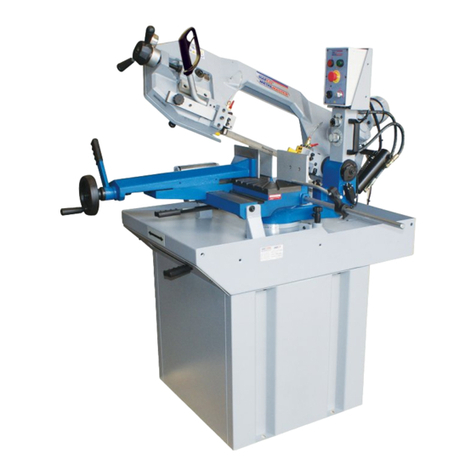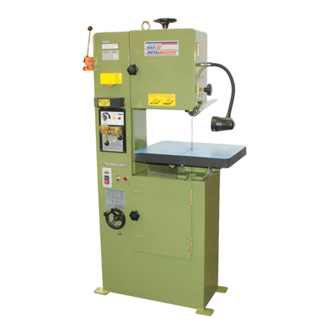
TABLE OF CONTENTS
1ACCIDENT PREVENTION AND SAFETY REGULATION..................................................................1
1.1 Advice for the operator.........................................................................................................................1
1.2 The electrical equipment according to European Standard" CENELEC EN 60204-1"........................1
1.3 Warning labels .....................................................................................................................................1
1.4 Emergencies according to European Standard “CENELEC EN 60204-1”..........................................1
2MACHINE TRANSPORTATION AND INSTALLATION.......................................................................2
2.1 Machine dimensions ............................................................................................................................2
2.2 Transporting the machine....................................................................................................................2
2.3 Minimum requirements for housing the machine.................................................................................2
2.4 Installing the rear coolant return tray ...................................................................................................2
2.5 Install the outlet tray, length stop device and mobile coolant trays. ....................................................3
2.6 Securing to foundation.........................................................................................................................3
2.7 Leveling the machine...........................................................................................................................3
2.8 Deactivation of machine.......................................................................................................................3
3DESCRIPTION OF MACHINE PARTS................................................................................................4
3.1 Control panel........................................................................................................................................4
3.2 The saw bow........................................................................................................................................4
3.3 The vise system...................................................................................................................................4
3.4 The base..............................................................................................................................................4
3.5 Chip tray...............................................................................................................................................4
3.6 Blade broken micro switch...................................................................................................................4
3.7 Chip brush............................................................................................................................................5
3.8 Open Blade Cover Safety Device........................................................................................................5
3.9 Speed change dial ...............................................................................................................................5
3.10Blade angle scale.................................................................................................................................5
3.11Attached coolant device.......................................................................................................................5
4SET UP AND PRE-OPERATIONS......................................................................................................5
4.1 Adjusting the tungsten carbide guides.................................................................................................5
4.2 Thrust Roller Adjustment .....................................................................................................................6
4.3 Adjusting the cutting precision.............................................................................................................6
4.4 Blade tracking adjustment....................................................................................................................6
4.5 Placing the saw blade onto the drive wheel and flywheel....................................................................6
4.6 Hydraulic vise pressure (optional)........................................................................................................7
5OPERATION PREPARATIONS...........................................................................................................7
5.1 Setting the saw blade height................................................................................................................7
5.2 Positioning the vise..............................................................................................................................7
5.3 Angle cutting ........................................................................................................................................7
5.4 Using the vise.......................................................................................................................................8
5.5 Adjusting the blade speed....................................................................................................................8
5.6 Changing the transmission belt............................................................................................................8
5.7 Changing the blade..............................................................................................................................8
5.8 Laser guide device (optional)...............................................................................................................9
5.9 Install the vertical press on the vise jaws for bundle cutting (optional)................................................9
6OPERATION CYCLE...........................................................................................................................9
6.1 Operation cycle....................................................................................................................................9
6.2 Stopping or emergency stopping.......................................................................................................10
7ROUTINE AND SPECIAL MAINTENANCE.......................................................................................10
7.1 Daily maintenance..............................................................................................................................10
7.2 Weekly maintenance..........................................................................................................................10
7.3 Monthly maintenance.........................................................................................................................10
7.4 Six-monthly maintenance...................................................................................................................10
7.5 Oils for lubricating coolant..................................................................................................................10
7.6 Oil disposal.........................................................................................................................................10
7.7 Special maintenance..........................................................................................................................10
7.8 Changing gear oil...............................................................................................................................10
8TECHNICAL CHARACTERISTICS....................................................................................................11
8.1 Table of cutting capacity and technical details ..................................................................................11
8.2 NOISE TESTS ...................................................................................................................................11
9CONTROL CIRCUIT DIAGRAM........................................................................................................12
10 PART LIST & EXPLOSION DRAWINGS...........................................................................................13
Instruction Manual for BS-321AS (B034A)


