Hafco Woodmaster T-13A User manual

INSTRUCTION MANUAL
T-13A
Thicknesser - Bench Mount (240V)
330 x 152mm
W813
Page 1
Instructions Manual for T-13A (W813)
11/09/2019

13” PLANER
User Manual
Read and understand this manual before using machine.
T-13A
Model Number
www.machineryhouse.com.au
www.machineryhouse.co.nz
Page 2
Instructions Manual for T-13A (W813)
11/09/2019

2
TABLE OF CONTENTS
INTRODUCTION
This user manual is intended for use by anyone working with this machine. It should be kept available
for immediate reference so that all operations can be performed with maximum efficiency and safety.
Do not attempt to perform maintenance or operate this machine until you have read and understand the
information contained in this manual.
The drawings, illustrations, photographs, and specifications in this user manual represent your machine
at time of print. However, changes may be made to your machine or this manual at any time with no
obligation to HAFCO Woodmaster.
INTRODUCTION
SECTION 1
SECTION 2
SECTION 3
SECTION 4
Definition of Terms...........................................................................................................................
SECTION 5
Feature Identification .......................................................................................................................
SECTION 6
General Safety.................................................................................................................................
SECTION 7
Product Safety .................................................................................................................................
SECTION 8
Electrical Requirements...................................................................................................................
SECTION 9
SECTION 10
SECTION 11
SECTION 12
SECTION 13
SECTION 14
Troubleshooting................................................................................................................................
Parts List...........................................................................................................................................
Product Specifications.....................................................................................................................
Grounding Instructions....................................................................................................................
Unpacking & Inventory.....................................................................................................................
Assembly..........................................................................................................................................
Adjustment.......................................................................................................................................
Operations........................................................................................................................................
Maintenance..................................................................................................................................... 19
16
13
12
11
9
9
8
5
4
3
21
23
3
www.machineryhouse.com.au
www.machineryhouse.co.nz
Page 3
Instructions Manual for T-13A (W813)
11/9/19

3
PRODUCT SPECIFICATIONS
Motor Specifications
Type Universal
Amps 10
Voltage 240V
Phase Single
Hertz
RPM 23000 ± 10% (No Load)
Product Specifications
26 FPM
etaR deeF
152 mm
3.4 mm
3.3 mm
1.5 mm
178 mm
330 mm
Maximum Thickness of Stock
Minimum Thickness of Stock
Maximum Depth of Cut @152.4 mm
Maximum Depth of Cut @330.2 mm
Minimum Length of Stock Maximum
Planing Width Cutterhead Speed
10000 RPM
Number of Blades
Cutterhead Diameter
T eziS elba
2
50.8 mm
330 x 236 mm
63 & 101 mm
troP tsuD
Product Dimensions
Height 483 mm
Width 508 mm
Depth 622 mm
Total Net Weight 25 kg
Shipping Dimensions
Height 508 mm
Width 558 mm
Depth 406 mm
Gross Weight 27 kg
DEFINITION OF TERMS
Cutterhead – A rotating piece of adjustable blades that
removes material from the workpiece.
Gum, Pitch, or Resin – A sticky, sap based residue
that comes from wood products.
Leading End – The end of the workpiece that is
pushed into the planer first.
Snipe – Gouging or depression of the board at the
ends. Snipe can occur at either the leading end of the
board going into the planer, or at the end of the board
as it exits the planer.
Workpiece – The piece of stock on which the work is
being done.
50
www.machineryhouse.com.au
www.machineryhouse.co.nz
Page 4
Instructions Manual for T-13A (W813)
11/9/19

4
FEATURE IDENTIFICATION
A. Infeed Table
B. Thickness Scale
C.
D.
Power Switch
E.
Raise/Lower Handle
Depth-of-Cut Indicator
F. Dust Port
A
B
E
D
F
C
www.machineryhouse.com.au
www.machineryhouse.co.nz
Page 5
Instructions Manual for T-13A (W813)
11/9/19

5
TO AVOID serious injury and damage to the machine,
read and follow all Safety and Operating Instructions
before assembling and operating this machine.
This manual is not totally comprehensive. It does not
and can not convey every possible safety and opera-
tional problem which may arise while using this
machine. The manual will cover many of the basic and
specific safety procedures needed in an industrial envi-
ronment.
Below is a list of symbols that are used to attract your
attention to possible dangerous conditions.
This is the safety alert symbol. It is used to alert you to
potential personal injury hazards. Obey all safety mes-
sages that follow this symbol to avoid possible injury or
death.
Indicates an imminently hazardous situation which, if
not avoided, WILL result in death or serious injury.
Indicates a potentially hazardous situation which, if not
avoided, COULD result in death or serious injury.
Indicates a potentially hazardous situation, if not avoid-
ed, MAY result in minor or moderate injury. It may also
be used to alert against unsafe practices.
CAUTION used without the safety alert symbol indi-
cates a potentially hazardous situation which, if not
avoided, may result in property damage.
This symbol is used to alert the user to useful informa-
tion about proper operation of the machine.
GENERAL SAFETY
DANGER
NOTICE
CAUTION
Exposure to the dust created by power sanding, saw-
ing, grinding, drilling and other construction activities
may cause serious and permanent respiratory or
other injury, including silicosis (a serious lung dis-
ease), cancer, and death. Avoid breathing the dust,
and avoid prolonged contact with dust.
2. ALWAYS wear eye protection. Any machine can
throw debris into the eyes during operations,
which could cause severe and permanent eye
damage. Everyday eyeglasses are NOT safety
glasses. ALWAYS wear Safety Goggles (that
comply with ANSI standard Z87.1) when operat-
ing power tools.
WARNING
CAUTION
Some examples of these chemicals are:
Κ Lead from lead-based paints.
Κ Crystalline silica from bricks, cement and other
masonry products.
Κ Arsenic and chromium from chemically-treated
lumber.
Always operate tool in well ventilated area and pro-
vide for proper dust removal. Use a dust collection
system along with an air filtration system whenever
possible. Always use properly fitting approved
respiratory protection appropriate for the dust
exposure, and wash exposed areas with soap and
water.
1. To avoid serious injury and damage to the machine,
read the entire User Manual before assembly and
operation of this machine.
!
!
!
!
WARNING
!
WARNING
!
WARNING
!
www.machineryhouse.com.au
www.machineryhouse.co.nz
Page 6
Instructions Manual for T-13A (W813)
11/9/19

6
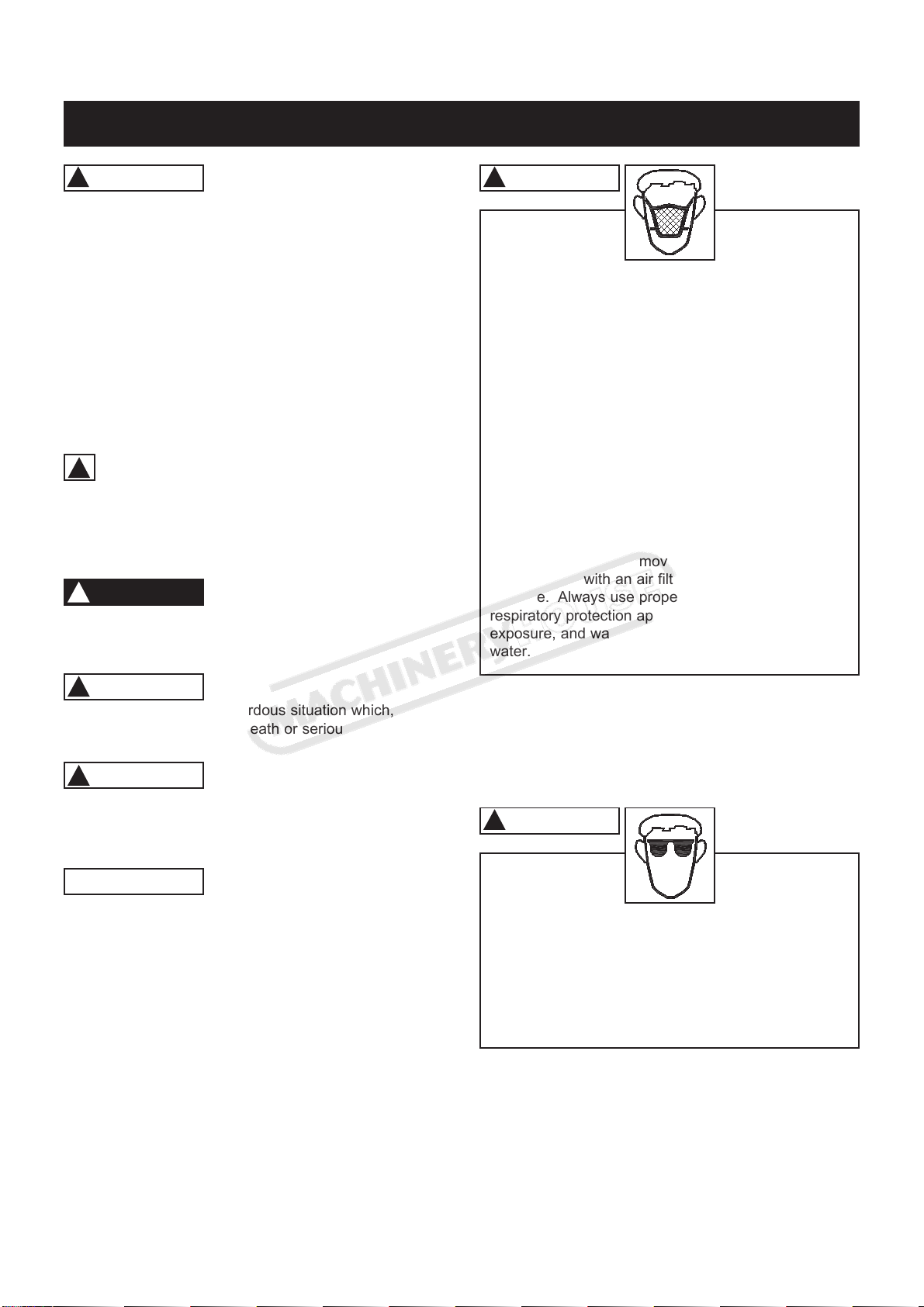
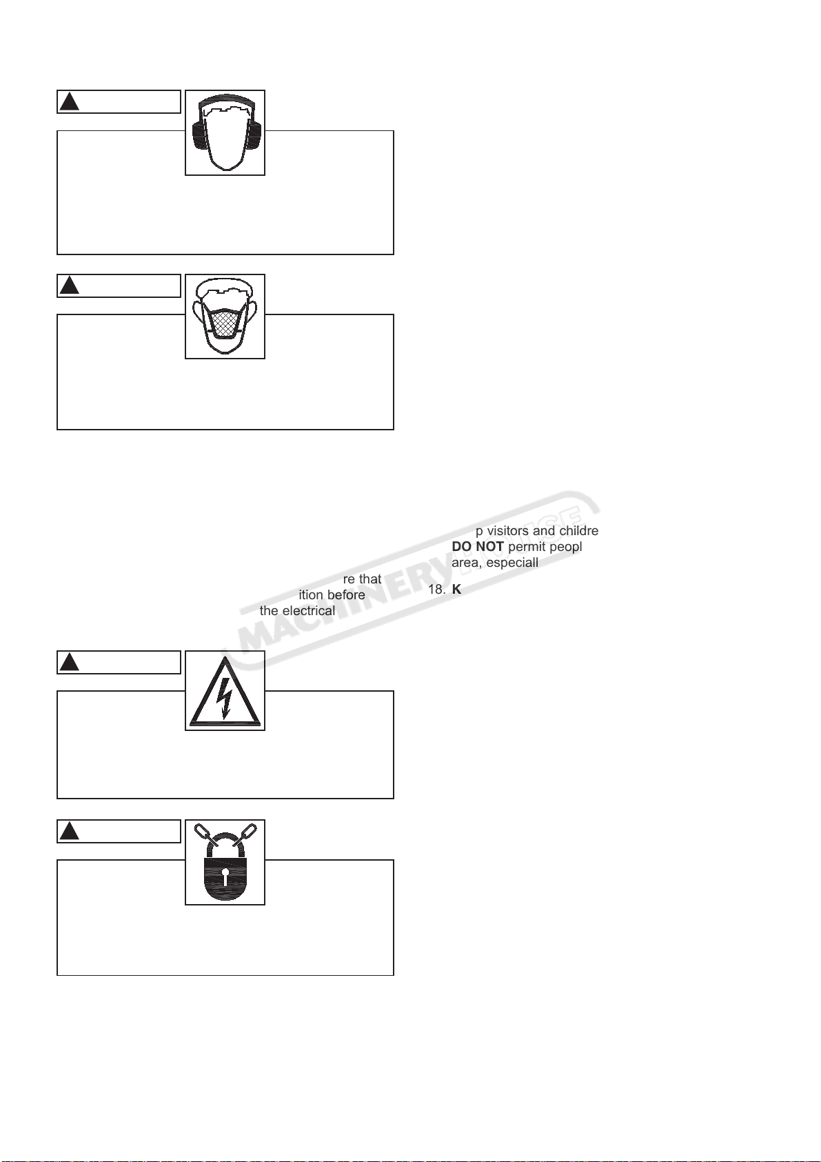
4. ALWAYS wear an approved dust mask to
prevent inhaling dangerous dust or air-borne
particles.
8. AVOID a dangerous working environment. DO
NOT use electrical tools in a damp environment
or expose them to rain or moisture.
9. CHILDPROOF THE WORKSHOP AREA by
removing switch keys, unplugging tools from the
electrical receptacles, and using padlocks.
3. ALWAYS wear hearing protection. Plain cotton is
not an acceptable protective device. Hearing
equipment should comply with ANSI S3.19
Standards.
10. DO NOT use electrical tools in the presence of
flammable liquids or gasses.
5. ALWAYS keep the work area clean, well lit, and
organized. DO NOT work in an area that has slip-
pery floor surfaces from debris, grease, and wax.
6. ALWAYS unplug the machine from the electrical
receptacle when making adjustments, changing
parts or performing any maintenance.
7. AVOID ACCIDENTAL STARTING. Make sure that
the power switch is in the “OFF” position before
plugging in the power cord to the electrical
receptacle.
11. DO NOT FORCE the machine to perform an opera-
tion for which it was not designed. It will do a safer
and higher quality job by only performing operations
for which the machine was intended.
12. DO NOT stand on a machine. Serious injury could
result if it tips over or you accidentally contact any
moving part.
13. DO NOT store anything above or near the machine.
14. DO NOT operate any machine or tool if under the
influence of drugs, alcohol, or medication.
15. EACH AND EVERY time, check for damaged parts
prior to using any machine. Carefully check all
guards to see that they operate properly, are not
damaged, and perform their intended functions.
Check for alignment, binding or breakage of all
moving parts. Any guard or other part that is dam-
aged should be immediately repaired or replaced.
16. Ground all machines. If any machine is supplied
with a 3-prong plug, it must be plugged into a 3-
contact electrical receptacle. The third prong is
used to ground the tool and provide protection
against accidental electric shock. DO NOT remove
the third prong.
17. Keep visitors and children away from any machine.
DO NOT permit people to be in the immediate work
area, especially when the machine is operating.
18. KEEP protective guards in place and in working
order.
19. MAINTAIN your balance. DO NOT extend yourself
over the tool. Wear oil resistant rubber soled shoes.
Keep floor clear of debris, grease, and wax.
20. MAINTAIN all machines with care. ALWAYS KEEP
machine clean and in good working order. KEEP all
blades and tool bits sharp.
21. NEVER leave a machine running, unattended. Turn
the power switch to the OFF position. DO NOT
leave the machine until it has come to a complete
stop.
22. REMOVE ALL MAINTENANCE TOOLS from the
immediate area prior to turning the machine ON.
23. SECURE all work. When it is possible, use clamps
or jigs to secure the workpiece. This is safer than
attempting to hold the workpiece with your hands.
24. STAY ALERT, watch what you are doing, and use
common sense when operating any machine. DO
NOT operate any machine tool while tired or under
the influence of drugs, alcohol, or medication. A
moment of inattention while operating power tools
may result in serious personal injury.
WARNING
!
WARNING
!
WARNING
!
WARNING
!
www.machineryhouse.com.au
www.machineryhouse.co.nz
Page 7
Instructions Manual for T-13A (W813)
11/9/19

7
25. USE ONLY recommended accessories. Use of
incorrect or improper accessories could cause seri-
ous injury to the operator and cause damage to the
machine. If in doubt, DO NOT use it.
26. THE USE of extension cords is not recommended
for 240V equipment. It is better to arrange the
placement of your equipment and the installed
wiring to eliminate the need for an extension cord.
27. Wear proper clothing, DO NOT wear loose clothing,
gloves, neckties, or jewellery. These items can get
caught in the machine during operations and pull
the operator into the moving parts. Users must
wear a protective cover on their hair, if the hair is
long, to prevent it from contacting any moving parts.
28. SAVE these instructions and refer to them frequent-
ly and use them to instruct other users.
www.machineryhouse.com.au
www.machineryhouse.co.nz
Page 8
Instructions Manual for T-13A (W813)
11/9/19

8
PRODUCT SAFETY
1. Serious personal injury may occur if normal safety
precautions are overlooked or ignored. Accidents
are frequently caused by lack of familiarity or failure
to pay attention. Obtain advice from supervisor,
instructor, or another qualified individual who is
familiar with this machine and its operations.
2. Every work area is different. Always consider safe-
ty first, as it applies to your work area. Use this
machine with respect and caution. Failure to do so
could result in serious personal injury and damage
to the machine.
3. Prevent electrical shock. All electrical connections
and wiring should be made by qualified personnel
only.
4. TO REDUCE the risk of electrical shock. DO
NOT use this machine outdoors. DO NOT
expose to rain. Store indoors in a dry area.
9. DO NOT handle the plug or jointer with wet hands.
WARNING
!
WARNING
!
5. STOP using this machine, if at any time you experi-
ence difficulties in performing any operation.
Contact your supervisor, instructor or machine serv-
ice center immediately.
6. Safety decals are on this machine to warn and
direct you to how to protector yourself or visitors
from personal injury. These decals MUST be main-
tained so that they are legible. REPLACE decals
that are not legible.
7. DO NOT leave the unit plugged into the electrical
outlet. Unplug the unit from the outlet when not in
use and before servicing, performing maintenance
tasks, or cleaning.
8. ALWAYS turn the power switch “OFF” before
unplugging the jointer.
11. DO NOT pull the jointer by the power cord. NEVER
allow the power cord to come in contact with sharp
edges, hot surfaces, oil or grease.
12. DO NOT unplug the jointer by pulling on the power
cord. ALWAYS grasp the plug, not the cord.
13. REPLACE a damaged cord immediately. DO NOT
use a damaged cord or plug. If the jointer is not
operating properly, or has been damaged, left out-
doors or has been in contact with water.
14. DO NOT use the jointer as a toy. DO NOT use near
or around children.
15. ENSURE that the machine sits firmly before using.
If the machine wobbles or is unstable, correct the
problem by using shims or blocks prior to operation.
16. This machine is designed to process wood ONLY.
17. NEVER position fingers or thumbs near the
infeed roller.
23. DO NOT attempt to remove jams until power is
disconnected and all moving parts have come to
a complete stop.
WARNING
!
WARNING
!
18. Long pieces of stock should ALWAYS be supported
with some type of fixture.
19. DO NOT operate jointer with dull or damaged
blades.
20. MAKE CERTAIN that the jointer is properly adjust-
ed prior to use.
21. DO NOT try and remove excessive amounts of
wood in one single pass.
22. INSPECT all stock before planing, ensuring that
there are no foreign objects embedded in the wood,
loose knots, or knots that may become loose during
operation.
24. MAKE SURE that there is adequate operating
space on both the infeed and outfeed sides of the
jointer before operating.
25. DO NOT attempt to plane wood that is less than
7” long or less than 1/8-inch thick.
10. USE only accessories as described in this manual.
www.machineryhouse.com.au
www.machineryhouse.co.nz
Page 9
Instructions Manual for T-13A (W813)
11/9/19

9
ELECTRICAL REQUIREMENTS
TO PREVENT electrical shock. All electrical
connections and wiring should be made by qualified
personnel only.
TO REDUCE the risk of electrical shock, DO NOT use
machine outdoors. DO NOT expose to rain or mois-
ture. Store indoors in a dry area.
DO NOT connect the machine to the power source
before you have completed the set up process.
DO NOT connect the machine to the power source until
instructed to do so.
The motors in these machines are designed to run on
240 volts.
GROUNDING INSTRUCTIONS
This machine MUST BE GROUNDED while in use to
protect the operator from electric shock.
In the event of a malfunction or breakdown, GROUND-
ING provides the path of least resistance for electric
current and reduces the risk of electric shock. The plug
MUST be plugged into a matching electrical receptacle
that is properly installed and grounded in accordance
with ALL local codes and ordinances.
If a plug is provided with your machine DO NOT modify
the plug. If it will not fit your electrical receptacle, have
a qualified electrician install the proper connections to
meet all electrical codes local and state.
IMPROPER ELECTRICAL CONNECTION of the equip-
ment-grounding conductor can result in risk of electric
shock. The conductor with the green insulation (with or
without yellow stripes) is the equipment-grounding con-
ductor. DO NOT connect the equipment-grounding con-
ductor to a live terminal if repair or replacement of the
electric cord or plug is necessary.
Check with a qualified electrician or service personnel if
you do not completely understand the grounding
instructions, or if you are not sure the tool is properly
grounded.
WARNING
!Fig. A
www.machineryhouse.com.au
www.machineryhouse.co.nz
Page 10
Instructions Manual for T-13A (W813)
11/9/19

10
EXTENSION CORDS
To reduce the risk of fire or electrical shock, use the
proper gauge of extension cord. When using an
extension cord, be sure to use one heavy enough to
carry the current your machine will draw.
The smaller the gauge-number, the larger the diameter
of the extension cord is. If in doubt of the proper size of
an extension cord, use a shorter and thicker cord. An
undersized cord will cause a drop in line voltage result-
ing in a loss of power and overheating.
USE ONLY a 3-wire extension cord that has a 3-prong
grounding plug and a 3-pole receptacle that accepts the
machine’s plug.
Make certain the extension cord is properly sized, and
in good electrical condition. Always replace a worn or
damaged extension cord immediately or have it
repaired by a qualified person before using it.
Protect your extension cords from sharp objects, exces-
sive heat, and damp or wet areas.
CAUTION
Κ Electrocution or fire could result if this machine is
not grounded properly or if the electrical configura-
tion does not comply with local and state electrical
codes.
ΚMAKE CERTAIN the machine is disconnected
from power source before starting any electrical
work.
ΚMAKE SURE the circuit breaker does not exceed
the rating of the plug and receptacle.
The motor supplied with your machine is a 240 volt,
50 hertz, single phase motor. Never connect the green
or ground wire to a live terminal.
A machine with a 240 volt plug should only be
connected to an outlet having the same configuration
as the plug.
WARNING
!
WARNING
!
!
PLUGS / RECEPTACLES
www.machineryhouse.com.au
www.machineryhouse.co.nz
Page 11
Instructions Manual for T-13A (W813)
11/9/19

11
Check shipping carton and machine for damage before
unpackaging. Carefully remove packaging materials,
parts and machine from shipping carton. Always check
for and remove protective shipping materials around
motors and moving parts. Lay out all parts on a clean
work surface.
Remove any protective materials and coatings from all
of the parts and the planer. The protective coatings
can be removed by spraying WD-40 on them and wip-
ing it off with a soft cloth. This may need to be redone
several times before all of the protective coatings are
removed completely.
UNPACKING & INVENTORY
After cleaning, apply a good quality paste wax to any
unpainted surfaces. Make sure to buff out the wax
before assembly.
Compare the items to inventory figures; verify that all
items are accounted for before discarding the shipping
box.
If any parts are missing, do not attempt to plug in the
power cord and turn “ON” the machine. The machine
should only be turned “ON” after all the parts have been
obtained and installed correctly.
WARNING
!
A. Handle
B. Dust Port
C. Hex Soc Head Screw
E
F
G
D
C
B
A
www.machineryhouse.com.au
www.machineryhouse.co.nz
Page 12
Instructions Manual for T-13A (W813)
11/9/19
D. Hex Soc head Cap Screw
E. Torx Wrench
F. Hex Wrench
G. Knife Removal Tool Assy

SECURING PLANER TO
A TABLE OR WORKBENCH
During operation, if there is any tendency for the planer
to tip over, slide or walk, the planer MUST be secured
to a supporting surface such as a workbench or table.
Four holes are provided (2 are shown at (A)) to secure-
ly mount the planer. The surface you are mounting the
planer to should be perfectly flat. SEE FIG 3.
Fig. 3
A
12
ASSEMBLY
ATTACHING DEPTH
ADJUSTMENT HANDLE
MAKE CERTAIN THAT THE MACHINE IS DISCON-
NECTED FROM THE POWER SOURCE.
WARNING
!
1. Attach the depth adjustment handle (A) to the shaft
(B) and fasten in place with 1 Hex Soc Head
screw. Tighten screw using supplied hex wrench.
SEE FIG 1.
Fig. 1 Fig. 2
ATTACHING DUST PORT
The Dust Port is to be used when the planer to be
connected to a dust collector. It has a 4” port on it to
accomodate most dust collection systems.
To install:
1. Install the dust port in the rear of the planer by
tigthening the soc head cap screws. (4) supplied.
SEE
FIG
2.
AB
www.machineryhouse.com.au
www.machineryhouse.co.nz
Page 13
Instructions Manual for T-13A (W813)
11/9/19

13
ADJUSTMENTS
LEVELING EXTENSION TABLES
The extension tables must be level with the planer
table. To check the extension tables and adjust if
necessary:
1. Lay a straight edge (A) on the planer table (C) with
one end of the straight edge over the infeed table
(B). SEE FIG 4.
Fig. 4
B
A
2. Check to make sure that the infeed table is level
with the planer table.
3. If an adjustment is necessary, loosen and adjust
Pan Head Screws (2) (D) on each side of the
table until the infeed table is level with the planer
table. This will adjust the outer edge of the infeed
table.
4. Repeat this process for adjusting the outfeed table.
RAISING AND LOWERING
HEAD ASSEMBLY
The head assembly consists of the cutterhead and
knives, feed rollers, cutterhead guard, and the motor.
Raising and lowering of the head assembly controls
the depth of cut on the planer. To adjust:
1. To raise the head assembly (A), turn the adjusting
handle (B) clockwise. SEE FIG 5.
Fig. 5
2. To lower the head assembly, turn the adjusting
handle counterclockwise.
NOTE: One revolution of the handle will move the
cutterhead up or down approximately 1/16”. You can
confirm this by referencing the scale (C) on the right
side of the planer.
A
B
C
C
D
www.machineryhouse.com.au
www.machineryhouse.co.nz
Page 14
Instructions Manual for T-13A (W813)
11/9/19

14
ADJUSTING / REPLACING KNIVES
The knives supplied with the planer have an edge on
both sides of the blade enabling you to flip the knives
over when one edge becomes dull or pitted. To change:
1. Remove the Dust Chute or Dust Port. Refer back to
the section labeled ATTACHING DUST PORT OR
DUST CHUTE in the ASSEMBLY section for infor-
mation on removing the Chute or Port.
2. Remove the cutterhead guard (A) by removing the
Hex Soc Head Cap Screws(B). SEE FIG 6.
MAKE CERTAIN THAT THE MACHINE IS DISCON-
NECTED FROM THE POWER SOURCE.
WARNING
!
Fig. 6
3.
BA
Hold the Cutterhead lock and rotate the cutterhead
with the supplied Hex wrench. Rotate it to the
position where the sharp edge of the blade is not
visiable from your sight angle. SEE FIG 7.
Loosen the screw on both sides and remove the
defector. Use the elevating handle to low down the
upper frame to 2”.
Fig. 7
4.
Use the supplied Hex wrench, insert it into the side
cover hole. Rotate it to the lock position. SEE FIG 8.
Using the supplied hex wrench, unscrew the eight
screws just enough so that the locking bar
separates from the knife, allowing the knife to be
removed. Do not completely remove the screws.
Insert the magnetic knife removal tool underneath
the center of the locking bar. SEE FIG 9 & 10.
5.
Fig. 8
Fig. 9
6.
Fig. 10
www.machineryhouse.com.au
www.machineryhouse.co.nz
Page 15
Instructions Manual for T-13A (W813)
11/9/19

Fig. 11
15
AB
Lift the tool up until the knife separates from the
pins and remove the knife.
Rotate the knife 180 degrees so that the edge of
the knife that was facing you is now facing away
from you and reinsert the knife. If you have already
used both edges of the knife, replace the knife at
this time
Place the magnetic knife removal tool on top of the
knife. Make sure that the tool is centered on the
knife.
Place the knife on the pins in the cutterhead and
remove the knife removal tool.
Retighten the eight screws loosened.
Repeat this process for the remaining knife.
NOTE: When placing the knives on the pins, you will
notice that there is some side to side movement
available in the knife. This is normal as it allows for
repositioning of the knives in case one of the knives gets
a nick in it.
NOTE: In order to rotate the cutterhead, you will have
to depress the red lever. This will unlock the cutterhead
allowing you to rotate it to the next knife to be changed.
THICKNESS SCALE ADJUSTMENT
The thickness scale, located on the right of the planer,
shows the thickness of the finished workpiece. To make
sure the scale is set properly, run a piece of wood
through the planer and measure the thickness of the
wood. If the scale is out of alignment, loosen the two
round head screws (A) holding the scale indicator (B)
and adjust the thickness indicator to the correct setting.
Make sure to re-tighten the two screws once the
adjustment is complete. SEE FIG. 11
7.
8.
9.
10.
11.
12.
www.machineryhouse.com.au
www.machineryhouse.co.nz
Page 16
Instructions Manual for T-13A (W813)
11/9/19

16
OPERATIONS
NOTICE: This operations section was designed to give
instructions on the basic operations of this planer.
However, it is in no way comprehensive of every planer
operation. It is strongly recommended that you read
books, trade magazines, or get formal training to maxi-
mize the potential of your planer while minimizing the
risks.
ALWAYS wear eye protection. Any machine can
throw debris into the eyes during operations, which
could cause severe and permanent eye damage.
Everyday eyeglasses are NOT safety glasses.
ALWAYS wear Safety Goggles (that comply with
ANSI standard Z87.1) when operating power tools.
ALWAYS wear an approved dust mask to prevent
inhaling dangerous dust or airborne particles.
WARNING
!
WARNING
!
WARNING
!
This planer is designed to process wood ONLY.
POWER SWITCH
The planer is turned on by flipping the switch into the
up position and it is turned off by flipping the switch in
the down position. This planer is also equipped with a
special lockout toggle switch that prevents unauthorized
use. To prevent unauthorized use of the planer, simply
pull out the yellow key (A) located on the face of the
switch. SEE FIG 12.
A
Fig.
12
DEPTH OF CUT SCALE
The Depth Of Cut Scale, located on the front of the
machine, is a convenient way to quickly determine how
much material is being planed off in one pass.
1. With the machine OFF, insert your workpiece just
under the depth of cut scale (A). SEE FIG 13
Fig. 13
B
A
www.machineryhouse.com.au
www.machineryhouse.co.nz
Page 17
Instructions Manual for T-13A (W813)
11/9/19

17
2. Crank the raising / lowering handle until the button
(B) comes in contact with the workpiece.
3. As you rotate the raising / lowering handle, the
needle on the depth of cut scale will move showing
you how much material will be removed in that
pass.
GETTING PREPARED
It is always a good idea to use a piece of scrap wood
for your first planing attempt. Also, before each use of
the planer, make it a habit of checking for loose fasten-
ers, fittings or hardware. Turn the planer ON and allow
it to reach full speed. Pay close attention to any exces-
sively loud noises that may be coming from the planer
or any excessive vibration. If either occurs, shut down
the planer immediately checking again for loose hard-
ware. Go through the ASSEMBLY and ADJUSTMENTS
sections again if necessary.
www.machineryhouse.com.au
www.machineryhouse.co.nz
Page 18
Instructions Manual for T-13A (W813)
11/9/19

18
BASIC OPERATION
To avoid serious personal injury, NEVER stand directly
in line with the front or rear of the planer. If an object is
thrown from the planer, it will travel in this direction.
1. Stand to either the left or right side of the planer.
2. Flip the switch to the ON position.
3. Lift the workpiece onto the infeed table by grabbing
the edges of the board at the middle of the length.
NOTE: For longer pieces, be sure to use additional
supports or stands
4. Push slightly on the board and allow the feed rollers
to pull the board through the planer. Once the feed
rollers start to pull the workpiece through, let go of
the board and allow the rollers to do their job. DO
NOT push or pull on the workpiece once the rollers
have engaged.
5. Move to one side of the rear of the planer and
receive the planed workpiece by grabbing the
edges of the wood, just like you did when feeding
the workpiece in.
6. It normally takes several passes of varying depths
to achieve a smooth finish, so repeat this process
as many times as necessary. Remember the less
you take off in a pass, the smoother the finish will
be.
THICKNESS PLANING
Thickness planing sizes the workpiece to a desired
thickness, while at the same time creating a smooth
and level surface. The thickness of each cut will
depend on the type of wood, width of the workpiece,
and condition of the workpiece (i.e. dryness, grain com-
position, straightness, etc). Always make thin test cuts
on a scrap piece of wood prior to performing cuts on
the workpiece.
WARNING
!
GENERAL TIPS AND GUIDELINES
Κ Thickness planing always works best when at least
one side of the workpiece has a flat surface. If both
sides of the workpiece are rough, feed one face of
the board over a jointer until the entire surface is flat
ΚALWAYS plane both sides of the workpiece to reach
the desired thickness
DO NOT plane workpieces less than 1/8-in thick, less
than 3/4-in wide, or shorter than 7-in long
Κ It is not recommended to use the planer at it’s maxi-
mum depth of cut (1/16”) and at it’s full width (13”).
Continuous use at the maximum settings will shorten
the life of the motor.
Κ Light cuts create a smoother finish than heavier cuts
Κ If a smooth cut is not obtained, try reversing the
board for proper grain orientation.
AVOIDING SNIPE
Snipe, gouging or depression of the board at the ends,
can occur when the board is not properly supported.
For workpieces longer than 4 ft, greater care must be
taken to reduce the problem because the additional
length of the workpiece translates into more unsup-
ported weight pulling down on the end of the board.
This unsupported weight will work against keeping the
stock flat. Make sure to use supports or stands when-
ever long pieces are being planed to avoid this prob-
lem. Since snipe occurs at the end of the boards, it is
good practice to start with a workpiece that is slightly
longer than what you need so that you can simply cut
www.machineryhouse.com.au
www.machineryhouse.co.nz
Page 19
Instructions Manual for T-13A (W813)
11/9/19

19
MAINTENANCE
Your planer should provide you with a long time of
service provided you take the time to perform the
following maintenance operations.
A quality paste wax should be applied to the planing
table surface to ease the movement of the workpiece
across it. Be sure to buff off all excess wax so that it
does not get absorbed into the wood when planing.
Having clean feed rollers is essential for optimal results.
Check feed rollers after each use for buildup of pitch,
gum, or resin and be sure to clean off with a non flam-
mable tar and pitch remover
Any moving parts should be cleaned regularly with a
penetrating oil and lubricated with a light coating of
medium weight machine oil
GEAR LUBRICATION
The gears in the gear box should be lubricated
periodically.
MAKE CERTAIN THAT THE MACHINE IS DISCON-
NECTED FROM THE POWER SOURCE.
WARNING
!
Fig. 14
2. Remove the side panel to expose the gear box
cover (B). SEE FIG 16.
3. Remove the two screws (C) in order to remove
the gear box cover and access the gear box
4. Place a light coat of multi purpose grease on the
teeth of the gears (D) and a light coat of spray
lubricant on the chain (E). Do not over-lubricate.
SEE FIG 17.
Fig. 15
Fig. 16
5. Replace all covers and guards that you removed
once lubrication is complete.
E
Fig. 17
C
B
D
Remove the socket head cap screw (A) located on
the top of the machine side panel. You will also
need to remove the pan head screw with washer
(B), located in the same position on the rear of the
planer. SEE FIG 14 & 15.
1.
A
www.machineryhouse.com.au
B
www.machineryhouse.co.nz
Page 20
Instructions Manual for T-13A (W813)
11/9/19
Table of contents
Other Hafco Woodmaster Planer manuals