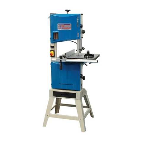
Hafco Woodmaster SB-12 User manual

Operator sManual
TABLE SAW
CAUTION: Read and followall SafetyRules
and OperatingInstructionsbeforeFirst Use
ofthis Product.
1306-TJZ10/2-TJZ12/2
W452 SB-12 5/6/2013

2
TABLEOFCONTENTS
Product Specifications................................................................................................................2
Safety.........................................................................................................................................3
AccessoriesandAttachments....................................................................................................5
Carton Contents.........................................................................................................................5
Assembly....................................................................................................................................7
Operation...................................................................................................................................10
Maintenance...............................................................................................................................12
Trouble ShootingChart..............................................................................................................12
AssemblyDiagram .. ............................................................................................................13
PRODUCTSPECIFICATIONS
Model TJZ10/2 TJZ12/2
Motor 2200W(3HP) 2200W(3HP)
TableSize 1030x685 mm 1030x685 mm
SawBlade 254 mm 305 mm
Max Cutting thickness 90°80mm/45°55mm 90°105mm/ 45°70mm
Blade angle 90°~45°90°~45°
Blade Speed 50Hz 3800r/ min 3800r/ min
60Hz 4560r/ min 4560r/ min
WARNING: Toavoidelectrical hazards, firehazards,or damagetothe machine,usepropercircuitprotection.
Useaseparateelectrical circuitforyourmachines.Toavoid shockorfire,replacepowercordimmediatelyifitis worn,cut
or damagedinanyway.
Application conditions
Thistablesawisdesignedforoperating underambienttemperatures between +50Cand 400Cand for
installationataltitudesnomorethan 1000mabove M.S.L.The surrounding humidityshouldless than
50%at 400C. It can be stored or transported under ambient temperatures between -250Cand 550C.

3
SAFETY
GENERAL
lBeforeputtingintouse,faultloop impedance and suitabilityofovercurrentprotectivedevices need
tobe approved according toyour safetystandards.
lReadthroughthe entireoperatinginstructions beforeputting intooperation.
lInaddition tothe safetyrequirementscontainedinthese operating instructions, you must be careful
toobserveyour country’sapplicableregulations.
lThe operatinginstructionsmustalwaysbe nearthe machine puttheminaplasticfoldertoprotect
themfromdirt and humidity.Theymustbe readbyeveryoperatorbeforebeginningworkand
observed conscientiously. Onlypersons who havebeen trained intheuseof the machine and have
been informed ofthe various dangersmayworkwiththe machine. Therequiredminimumage must
be observed.
lInaddition tothe safetyrequirementscontained inthese operating instructions and yourcountry’s
applicableregulations,you shouldobservethe generallyrecognized technicalrules concerning the
operation ofwoodworkingmachines.
lThe machine mustonlybeused intechnicallyperfectconditioninaccordance withitsdesignated
use andthe instructions set out inthe operatingmanual, and onlybysafety-consciouspersons who
arefullyawareoftheriskisinvolved inoperating themachine.Anyfunctionaldisorders,especially
those affecting the safetyofthe machine; shouldthereforebe rectified immediately.
lObserveall safetyinstructions and warningsattachedtothe machine.
lSee toitthatsafetyinstructionsandwarnings attached tothe machinearealwayscompleteand
perfectlylegible.
lCaution when working,Thereisadanger tofingersand hands fromrotating cutting tools.
lMakesurethat machine stand isstableon firmground.
lCheckall power supplylines. Donot usedefectivelines.
lKeepchildren awayfromthe machinewhen it isconnected tothe power supply.
lOperatingpersonnelmustbe at least 18 yearsofage.
lPersons working on themachine must not be distracted fromtheir work
lThe machinemustbe equipped withatablelengthextension ifsecond person isworking atthe
circular saw removing cutworkpieces.The second person must not stand anywhereelse but at the
take-offtableend.
lThe working spaceon themachine must be free ofchipsandwood scrap.
lWear onlyclose-fittingclothes. Removerings, braceletsand other jewelry.
lAlwayswear adustmask, safetygoggles and hearing protection whenoperating the machine..
lThe workareashouldbe properlylit.
lPayattention tothe rotationaldirection ofthe motor - see ElectricalConnection.
lThe safetymechanismsonthe machine must not be removed or rendered unusable.
lCleaning,changing,calibrating,andsettingofthe machine mustonlybe carriedoutwhen the motor
isswitched offand the machineisdisconnected fromitspowersource.Removepowersupplyplug
fromsocket and wait for the rotatingblade tocompletelystop.
lPayattention tothe hazardofcuttingwhen handlingsawblades,groovingtoolsfeedingwood into
the machine or conductingmaintenance.
lNevertryremoving chipswhilstthe sawbladeisrunning andthe sawblade isnotinthe rest
position.
lNevertryusing the machine unless allofthe guardsand othersafetydevices necessaryforsafety
areingood working order.
lSwitch the machineoffand removepowersupplyplugfromsocketwhen rectifying any
malfunctions.
lWhenworkingon the machine, all safetymechanismsand coversmust be mounted.
lUse onlysharpened, nick-free and non-deformedsaw blades.

4
lThe splittingwedge isan importantsafetyfeature.The workpiece isfed through the splitting wedge
which preventsthe cutfromclosing behind thesawbladeandalso preventsthe workpiecefrom
kickingback.
lLowerthe bladeguardontothe workpieceduring everyworking operation.It muststand
horizontallyabovethe saw blade.
lAlwaysuse apush-stickforlongitudinalcutsofnarrowworkpieces (lessthan 120 mm).The
push-stickmustbe usedtopreventyou fromhavingtoworkwithyourhandsnearthe sawblade.
Stop the machineand disconnect the mains plug torepair afailureor removepieces ofwood which
havebecomejammed.
lThe tableinsert mustbe renewed when the sawslotisworn.Removepowersupplyplugfrom
socket.
lWhenleavingthe workplace, switch the motor off.Removepower supplyplugfromsocket.
lCutoffthe externalpowersupplyofthe machineorplanteven ifonlyminorchanges ofplace are
envisaged. Properlyreconnect the machinetothe supplymains beforerecommissioning.
lConnection and repairworkonthe electricalinstallation mustbe carriedoutbyaqualified electrician
only.
lAllprotection and safetydevices mustbe replaced aftercompletingrepairand maintenance
procedures.
lAdequatelightingshall be provided whenworking.
Use onlyas authorized
lThe machine hasbeenbuilt inaccordancewithstateofthe art standards andthe recognized safety
rules.Nevertheless,itsuse mayconstitutearisktolifeandlimbofthe userorofthirdparties or
cause damage tothe machineand toothermaterialproperty.
lThe tablesawisconstructed exclusivelyforthe sawing of wood.Therequired sawbladeshouldbe
insertedaccording tothe cut type and the wood type (solidwood, chipboardor plywood).
lThe machinemustonlybeusedinatechnicallyperfectconditioninaccordance withitsdesignated
use andthe instructions set out inthe operatingmanual, and onlybysafety-consciouspersons who
arefullyawareofthe risks involved inoperatingthemachine.Anyfunctionaldisorders,especially
those affecting the safetyofthe machine, shouldthereforebe rectified immediately.
lAnyotheruse exceeds authorization.The manufacturerisnotresponsibleforanydamages
resulting fromunauthorized use; riskisthe soleresponsibilityofthe operator.
lThe safetyworkandmaintenanceinstructionsofthemanufactureras well aswell as the technical
datagiven inthe calibrations and dimensions must be adhered to.
lRelevantaccidentprevention regulations and other,generallyrecognized safety-technicalrules
must alsobe adhered to.
lThe TableSawmayonlybe used,maintained,andoperated byoperated bypersonsfamiliarwith
and instructedinitsoperation and procedures.Arbitraryalterations tothe machine release the
manufacturer fromall responsibilityfor anyresultingdamages.
lThe TableCircularSawmustonlybe used withoriginalaccessoriesandsawblades fromthe
manufacturer.
Remaining hazards
The machine has been builtusing moderntechnology inaccordancewithrecognized safetyrules.Some
remaininghazards however, maystill exist.
lThe rotating saw blade cancauseinjuries tofingersand hands if the workpieceisincorrectlyfed.
lThrownworkpieces can lead toinjuryif the workpiece isnotproperlysecuredorfed due toworking
without alimit stop.
lNoise can be ahealthhazard.The permitted noiselevelisexceeded when working.Besuretowear
personalprotectiveequipment such asear protection.
lDefectivesaw blades cancause injuries. Regularlyinspect the integrityofsaw blades.
lThe operatinginstructionssuppliedwiththe specialaccessories mustbe observed and carefully
read when theyareused.

5
lEven whenallsafetymeasures aretaken,someremaininghazards whicharenotyetevidentmay
stillbe present
Electrical Connection
The electricmotor isconnected inareadytooperatestate.
The mainsconnection atthe customer’sworkplaceand the extension cableused mustcorrespond to
these regulations.
Faultyelectrical connecting leads
Insulation damage often occursat electricalconnecting leads.
Causes include:
lPressuremarkscaused when connecting leads arerun through windowsor the cracksofdoors.
lFolds causedbythe improper attachment ofrunningofthe connectingleads.
lCutsresulting fromthe crossing ofthe connecting lead.
lInsulation damage causedbythe ripping out ofthe connecting leadfromthe wall socket.
lCracks due tothe ageing ofthe insulation.
Faultyelectricalconnectingleads suchas these mustnotbe used and arehighlydangerous due tothe
insulation damage.
Checkelectrical connectingleads regularlyfordamage.Ensurethatthe connecting lead isnotattached
tothe mains supplywhen you arechecking it.
Please chooseproperpowersource,voltage and frequencythatareshownon the labelforyourdrill
press.
Extensionleads up to25minlengthmusthaveaminimumcross-section of1.5mm².Extension leads
whose lengthisover 25mmust haveacross-section ofat least 2.5mm².
Connectionsorrepairson theelectrical equipment must onlybecarriedout byanelectrician.
ACCESSORIES AND ATTACHMENTS
RECOMMENDEDACCESSORIES
Toavoidinjury:
•Use onlyaccessories recommended for thismachine.
•Follow instructions that accompanyaccessories. Use ofimproper accessoriesmaycausehazards.
•Use onlyaccessories designed for thistablesaw toavoidinjuryfromthrownbroken partsor work
pieces.
•Donot use anyaccessoryunless you havecompletelyread the instructionsor operator’smanualfor
that accessory.
CARTONCONTENTS
UNPACKINGAND CHECKING CONTENTS
Carefullyunpackthe tablesaw and allitsparts, andcompareagainst the illustration following.
WARNING:
•Toavoidinjuryfromunexpectedstarting, do not plug the power cordintoapower source receptacle
duringunpacking and assembly. Thiscordmust remainunplugged whenever you areassemblingor
adjustingthe machine.
•Ifanypart ismissing or damaged, do not plug the machine until the missingor damaged part is
replaced, andassemblyiscomplete.
•Toprotect the tablesawfrommoisture, aprotectivecoating has been appliedtothe machined
surfaces.
Removethiscoating withasoft clothmoistenedwithkerosene.
WARNING: Toavoidfireortoxicreaction,neveruse gasoline,naphtha,acetone,lacquerthinnersor
similar highlyvolatilesolventstocleanthe tablesaw.

6
TABLE OFLOOSE PARTS
Unpackcarton; checkyoumachine tosee partslistedbelow:
1.Ripfence 1pc
2.Backfence support 1pc
3.Dadoinsert 1pc
4.Blade guardassembly1pc
5.Motor assembly1pc
6.V-belt1pc
7.Belt guard1pc
8.Miter gauge 1pc
9.Wrench 1pc
10.Extensiontable2pcs
11.Tablecabinet assembly1pc
12.Front fence support 1pc
13.Handwheel2pcs
14.Lockknob 2pcs
15.Front/rear top frame2pcs
16.Front/rear brace2pcs
17.Leg 4pcs
18.Side brace2pc s
19.Side top frame2pcs
20.Hardwarebag (not shown)1pc
21.Operator’manual(not shown)1pc
1
10
3
4
5
6
7
2
9
18
8
19
11
12
13
14
16
17
15

7
Assembly
Important:Whenunpacking, take caretolocateall thesmall partsof themachinesuppliedinside
thecartonbox.
Assemble standwithM8hex nuts,8mmflatwashersand M8X16 carriage bolts.Then install thetable
cabinetassemblytothe stand andsecureitwithM8X16 hex head bolt, 8mmflatwasherand M8hex nut.
Assemblethe motorassemblytothe twosupport shaftsofthe machine,Fixitbytightening thesetscrew.
Adjustmotor toalign the motor pulleywithblade driving pulley.
Installthe v-belt
Assemblethe belt guard.
Connect the connectorsof the cord.
M8X16 hex
bolt
M8X16
carriage bolt
Set screw
cordconnector
Belt guard

8
Assemblethe height adjusting hand wheelsand angleadjustinghandwheel.
Attach the twolockknobs.
Assemblethe extension tablewithM8hex head boltsand 8mmflat washers.
Adjust set screwstomaketables flush and level.Then tightenthe bolts.
Slide fourM8X25 hex boltsintothe frontfence support, then fixthe frontfencesupport assemblytothe
tablebyfour M8nutsand four 8mmflat washers.
Inthe sameway, fixthe backfence support tothe table
M8hexboltand8mm
flat washer
Levellingruler
Extensiontable
M8x25 hex bolt
Angleadjusting
hand wheel
Heightadjusting
hand wheel
Lockknob

9
Assemblethe switch box tothe front fencesupport and fixit withscrewsand nuts
Place the ripfenceupon the fence support. Ensurethe fence bottomsurfaceisparallelwiththetable
surface byadjustingthe height ofthe fencesupport.
Adjustthe fourscrews(A)tomake fenceparallelwiththe blade.Movethe fence totouch theblade and
adjust the scaleindicator tozero.
Front fence support
Backfence support
Switch box
A
Ripfence

10
Removethe tableinsert.
Assemblethe blade guardassemblywithtwoM6X10hex boltsand6mm flatwashers.Alignthe riving
knifewiththe blade andtighten the bolts.
After allthese steps, the machine’sassemblyisfinished.
Operation
Preparethe workplace wherethe machineistobeplaced.Insuresufficientroomtoallowsafework
without interference.The machine isdesigned tooperateinclosed rooms.
Important: The machinemust onlybe brought intoservice completewithprotectiondevices.
Beforeswitching on the machine,allsafetyand protection devices havetobe installed according tothe
instructions.
Alwayschecktimber,whichhas been processed before,forforeign objects(nails,screws,etc.). Remove
all foreignmatter.
Beforeturning on the powersupply,make surethatthe sawblade isinstalled correctlyand thatall
moving componentscanmovefreely.
Warning: Ifindoubt, havethe machinesetbyaqualifiedperson.It istoo dangeroustoworkon
assumptions.
SawBlade –DiagonalAdjustment
The sawblade maybe swiveled from90°to45°byturning the handwheelafterthe locking knob has
been loosened.
Checkthe 90°and the 45°position beforethe first and each subsequent startup.
SawBladeHeightAdjustment
The saw blade isadjustablefrom0to100 mmcuttingheight
For safeandclean working, choosethe minimalsaw blade projectionfor the workpiece.
M6X10 hex boltsand
6mmflat washers
M6X10 hex boltsand
6mmflat washers

11
Parallel cuts
Adjustthe ripfence inaccordance withthe widthofwork
piece.Withbothhands (use the push-stickinthe region of
the saw blade) and push the workpiece untilit isbehindthe
riving knife.Use the push –sticktofeed the workpiece right
fromthe beginning ofthe cutting process ifshort work
pieces arebeing used..
Cross cuts
Warning:theworkpiece mustbesecuredagainst
rotationbyusing asuitablejigorholderwhen
cross-cuttingroundstock.Atthesametimeasuitable
sawbladeshall beused.
Adjustthe mitergauge tonottouch the sawblade.Only
feedthe workpiece bymeans ofacross slide.
Donotremovewood chippings fromthe regionofthe work
piecewithyour hands.
Concealedcutting, rebating
Whenperformingrebating workatthe fence rail,selectthe
cutting sequencewhich ensuresthatthe cut-offstripfalls
ontothe side ofthe sawblade facingawayfromthe fence
rail. Removethe blade guardand theriving knifetoperform
concealed cuttingorrebating work.Ensurethatthe work
pieceisguided properly. Re-installthe guardwhen finished.
Angleadjusting
hand wheel
Heightadjusting
hand wheel
Lockknob

12
Maintenance
Warning: Beforeperforming anymaintenance,make surethemachine isunplugged fromthe power
supply.
Wear goggleswhen cleaning the machine.
Caution: Donotclean syntheticcomponentsofthe benchusing aggressivecleaning agents.We
recommend amilddish washing liquid.Themachinemust not get intocontact withwater.
lTurnonand then offtocheckthe brake stopsthe blade within10Severyweek.Ifnot, checkand
repair the mechanicalbrake.
lCheckthe saw bladeregularly. Useonlywell sharpened, crack-free and un-distorted blades.
lAlwayskeeptablesurface free fromresins.
lClean regularlythe inside ofthe machinefromwoodand chips.. Clean outthe sawdustinthe blade
teethbyusing asoft brush.
lRemovepossiblesawdust blockagesat the discharge.
lCheckpush blockhandlesand push sticksbeforeeach use ofthe machine.Changedthemifthey
aredamaged.
lIfablockage occurs,turnoffthe machineand removepowersupplyplug fromsocket. Removethe
blockagebyusing thepushstickwhen thesaw bladeisstationary.
Trouble ShootingChart
Warning:intheinterestsofoperationalsafety,alwaysswitchoff thesawand disconnectthe
mainsplug beforecarrying out maintenance work.
Problem Possiblecause CorrectiveAction
Excessivevibration 1. Blade out ofbalance
2.DamageV-beltpulleysorpoor
belt
1.Discardbladeand use adifferent
blade
2. Replaceas indicated
Cannotmakesquarecut
when crosscutting Mitregauge not adjustedproperly Adjustmitregauge
Blade stalls(however,
motor turns) 1. Beltsnot tight
2. Belt worn 1.Adjust belt tension
2. Replacebelt
Cutbinds,burns orstalls
when ripping 1. Dullbladewithimproper toothset
2.Blade isbinding atone endof
cut(heeling)
3.Warpedboard
4. Ripfence not paralleltoblade.
5. Spreader out ofalignment
1. Sharpen or replace blade
2.Adjusttableandripfence parallel
toblade
3.Make sureconcaveorhollowside
isfacing down;feedslowly
4.Adjust ripfence
5.Adjustspreadertofall inline with
blade
Tiltandelevatinghand
wheeldifficult toturn Sawdust on rackandwormgears Clean and re-lubricate
Frequentblowingoffuses
ortripping ofcircuit
breakers
1. Motor overloaded
2.Fuses orcircuitbreakersdo not
havesufficient capacity
1. Feed workslower intoblade
2.Installpropersizefusesorcircuit
breakers

13
AssemblyDiagram
Partlistfor bladeguard
Reference
number Description Quantity
1 Pushnut 4
2 Spring pin 1
3 Anti-kickbackpawl 2
4 Bushing2
5 Riving knife 1
6 Guardsupport 1
7 Spring 1
8 Pin 1
9 Blade guard 1
10 Label1
11 Pin1
12 M6X10 Hex bolt 2
13 6mmflat washer 2

14
Partlistfor ripfence
Reference
number Description Quantity
1 Locknut 1
2 Rivet2
3 Rivet2
4 Flitch plate 1
5 Clamp 1
6 Plasticbracket 1
7 Ring 2
8 Idler wheel 1
9 Fence1
10 Support plate 1
11 Spring pin 2
12 Guide plate 1
13 Short shaft 1
14 Bushing2
15 Handleplate 2
16 Threaded rod 1
17 Nut1
18 Clamphandle 1
19 Space plate 1
20 Fencecover 1
21 Screw2
22 Pan head screw 4
Reference
number Description Quantity
23 Junction plate 1
24 Nut4
25 Screw4
26 Screw42
27 Left cover 1
28 Bracket1
29 Right cover 1
30 Pan head screw 1
31 Flat washer 1
32 Pointer1
33 Nut1
34 Set screw 1
35 Adjusting handle 1
36 Spring 1
37 Bushing1
38 Set screw 1
39 Pan head screw 2
40 Gear bracket 1
41 Nut2
42 Gear shaft 1
43 Gear1

Partlistfor stand
Reference
number Description Quantity
1 Tablecabinet assembly 1
2 Leg 4
3 Front/rear brace 2
4 Front/rear top frame 2
5 Side top frame 2
6 Side brace2
7 M8X16 hex bolt 4
8 Flat washer 24
9 Lockwasher 24
10 Hex nut24
11 Carriage bolt 16

16
Partlistfor table
Reference
number Description Quantity
1 Screw4
2 Fencesupport cover
1
3 Front fence support 1
4 Scale1
5 Fencesupport cover 1
6 Nut14
7 Flat washer 12
8 Pan head screw 14
9 Rack4
10 Table1
11 Screw4
12 Spring plate 4
13 Tableinsert 1
13A Dadoinsert 1
14 Set screw 4
15 Extensiontable 2
Reference
number Description Quantity
16 Hex bolt4
17 Flat washer 4
18 Hex nut4
19 Backfence support 1
20 Flat washer 6
21 Hex bolt 6
22 Nut1
23 Washer1
24 Switch box cover 1
25 Support plate 1
26 Switch box 1
27 Pan head screw 2
28 Screw4
29 Switch 1
30 screw 3
31 Miter gauge assembly
1

17

18
Partslistfor bladedriveand tiltmechanism
Reference
number Description Quantity
1 Cabinet 1
3 Pan head screw 6
5 Hex nut6
6 Flat washer 20
7 Support 1
8 Hex bolt 2
9 Hex bolt 4
12 Cordclamp 2
13 Hex nut 6
14 Flat washer 4
15 Hex bolt 4
16 Motor1
17 Pulleycover bracket
1
18 Set screw 3
19 Motor pulley 1
20 Key1
21 V-belt 1
22 Pulleycover 1
23 Socket head bolt 4
24 Lockwasher 4
25 Rear bracket 1
26 Rear trunnion 1
27 Motor bracket 1
28 Set screw 3
29 Motor plate1
30 Pivot shaft 1
31 Drivepulley 1
32 Hex nut 1
33 Lockwasher 1
34 Ball bearing 2
35 Wavy washer 4
36 Arbor bracket 1
37 Arbor1
38 Blade 1
Reference
number Description Quantity
39 Blade flange 1
40 Arbor nut 1
41 Pin1
42 Spring pin2
43 Spring pin 4
44 Wormgear 2
45 Spacer1
46 Elevation shaft 1
47 Set screw 2
48 Eccentricsleeve 1
49 sleeve 1
50 Linkingbar 2
51 Socket head bolt 1
52 Handwheel 2
53 Handle2
54 Locking knob 2
55 Collar2
56 Set screw 2
57 Tilt shaft 1
58 Front trunnion 1
59 Front bracket 1
60 Indicator1
61 Spacer1
62 Flat washer 1
63 Hex nut 5
64 Hex nut3
65 Hex bolt 1
66 Set plate 1
67 Flat washer 2
68 Hex bolt 2
69 Strainrelief 1
70 Motor cord 1
71 Linecord 1
This manual suits for next models
3
Table of contents
Other Hafco Woodmaster Saw manuals

Hafco Woodmaster
Hafco Woodmaster TAFE-BP-480 User manual

Hafco Woodmaster
Hafco Woodmaster MJ2325D User manual

Hafco Woodmaster
Hafco Woodmaster BP-480 User manual

Hafco Woodmaster
Hafco Woodmaster TAFE-BP-480 User manual

Hafco Woodmaster
Hafco Woodmaster BP-255 User manual

Hafco Woodmaster
Hafco Woodmaster BP-430A User manual

Hafco Woodmaster
Hafco Woodmaster BP-305 User manual

Hafco Woodmaster
Hafco Woodmaster W4346 User manual