HE&M H90A-1 User manual

1
BLADE CHANGE
FOR
HORIZONTAL
AIR SAW
MACHINES

2
Changing the Blade
NOTE: The procedure described is applicable to all Air Saws but may not visually reflect some
saw models.
REMOVING THE BLADE
CAUTION!!!!
Wear gloves to protect hands while
changing blades. Band Saw blades are extremely sharp
and can cause serious cuts, amputation, or death unless
necessary precautions are taken.
1. Adjust the Upper Stop Limit Collar to raise
the arm about 6”, or enough that the band wheel
doors can be opened over the vise. In some
cases, especially if the saw is equipped with
optional top clamps, it may be easier to swing
the arm slightly to a miter position, if it is a
mitering band saw.
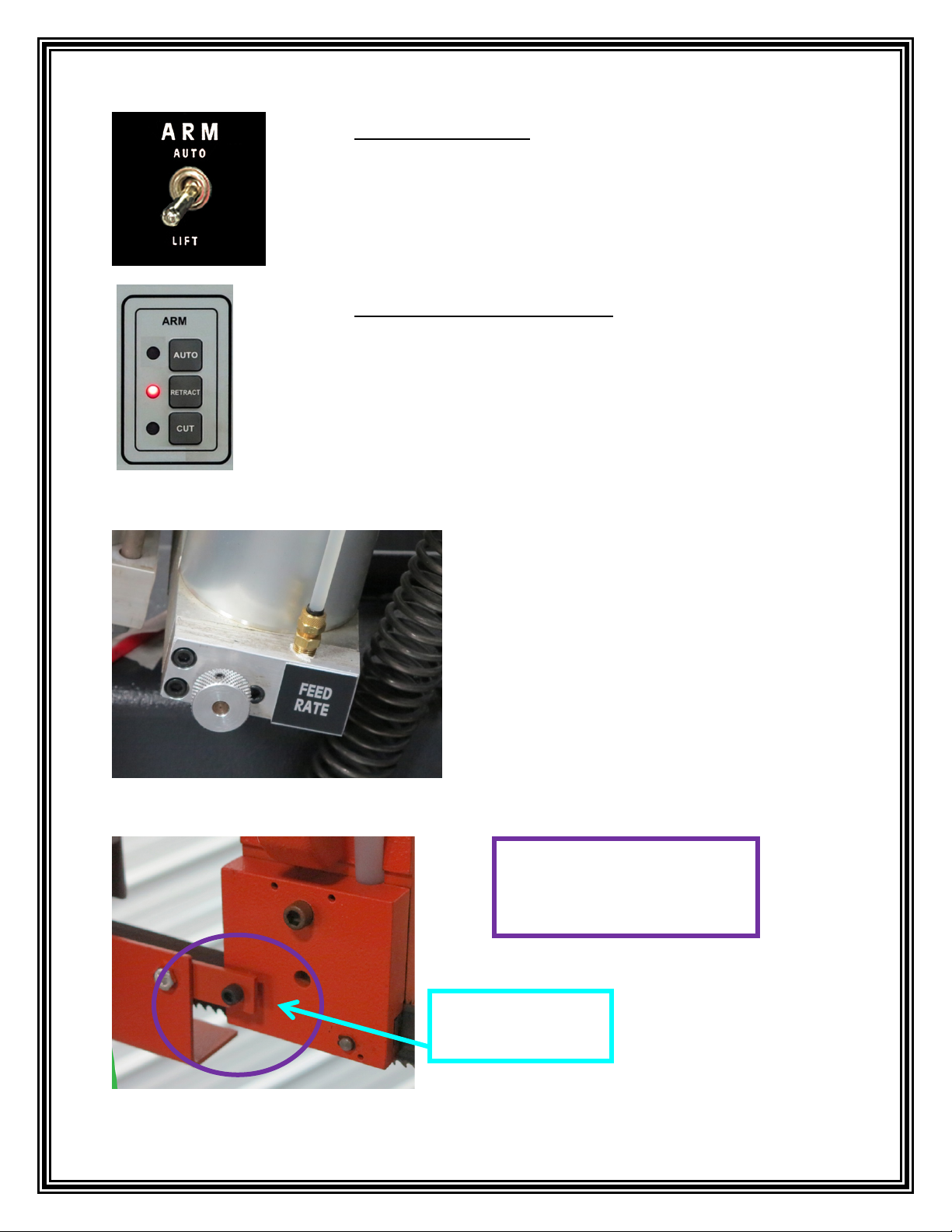
2. FOR MANUAL AIR SAWS: Place the ARM Switch into the
“LIFT” position on the control panel to raise the arm to the
position previously set by the Upper Stop Limit Collar.
3
2. FOR A-4 AND A-C AIR SAWS: Press the ARM
“RETRACT” button on the control panel to raise the arm to the
position previously set by the Upper Stop Limit Collar.
4. Raise the Sliding Blade
Guard Latch.
SLIDING BLADE
GUARD LATCH
2. FOR A-1 AIR SAWS: Move the ARM Switch down to the
“LIFT” position to raise the arm to the position previously set by
the Upper Stop Limit Collar.
3. Turn the Feed Rate Knob completely to the
right by turning the knob clockwise. This will
close the Feed Rate air flow out from the
cylinder to prevent the saw arm from falling
during a blade installation/change.

4
Sliding Blade Guard
6. Slightly loosen the Guide Cap Allen Bolts located on both sides of the saw blade.
7. Turn the Blade Tension Handle to remove the blade tension. Turn the handle counter
clockwise to loosen and clockwise to tighten. Stand aside when doing this. DO NOT STAND
IN FRONT OF THE TENSION HANDLE. The tension handle is under great tension and
will cause injury if it comes out.
BLADE TENSION
HANDLE
Tension on the blade
is released.
5. Move the Sliding Blade Guard out of
the way.

5
9. Using both hands, push the saw
blade down and out of the guide caps.
CAUTION!! Be careful as the blade
will attempt to un-twist when it
comes out of the guides.
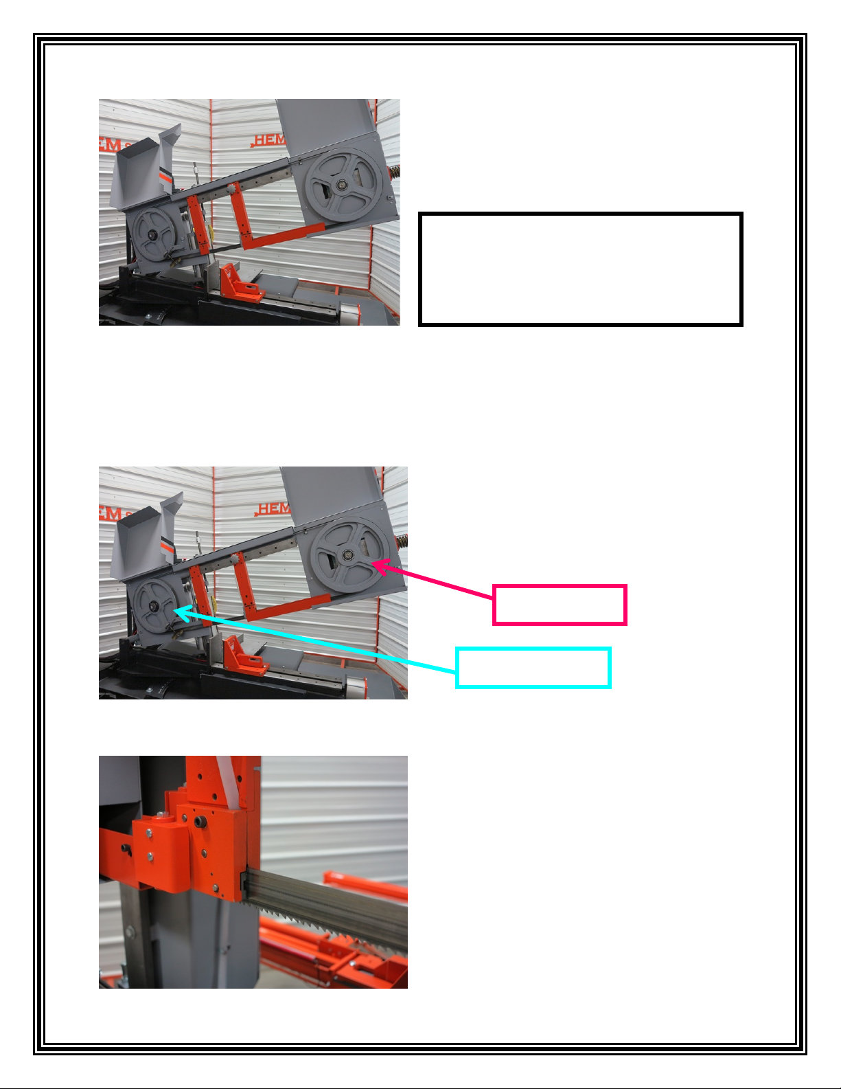
10. To remove the blade the Drive and Idle Wheel
Covers must be open. To open the Drive and Idle
Wheel cover there are door handles located on each
wheel cover. Lift up on the door handles to open the
wheel covers.
DOOR HANDLE
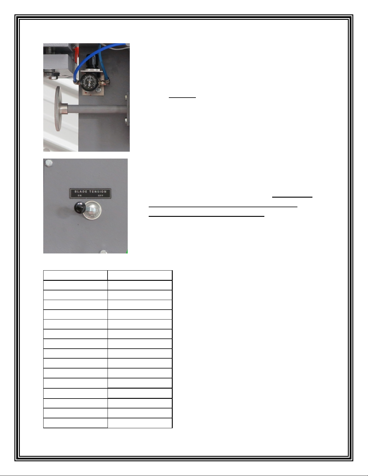
8. When changing the blade on
models with the Optional Air-
Powered Blade Tensioner, first turn
the Blade Tension lever to “OFF”.
Then turn the Blade Tension Knob
to loosen the blade enough to be
removed from the band wheels.
NOTE: This step is ONLY for
Saw Models equipped with the
Optional Air Powered Blade
Tension.
BLADE TENSION
SWITCH
BLADE TENSION
KNOB
6
INSTALLING A NEW BLADE
11. Once the wheel covers have been raised,
slip the blade off of both wheels and
carefully remove the blade from the saw.
1. Once the old blade has been removed
the new blade can be installed. Place the
blade around the Drive and Idle Wheels
with the blade teeth facing outward.
IDLE WHEEL
DRIVE WHEEL
NOTICE!!!! Be careful when handling saw
blades so that the tooth edge is not damaged.
A chipped or broken tooth will cause cutting
problems.
2. If Guide Caps have been removed to
clean the Blade Guides, replace the Guide
Caps but leave them loose enough to be
enable sliding the blade up between the
Carbide Blade Guides.
7
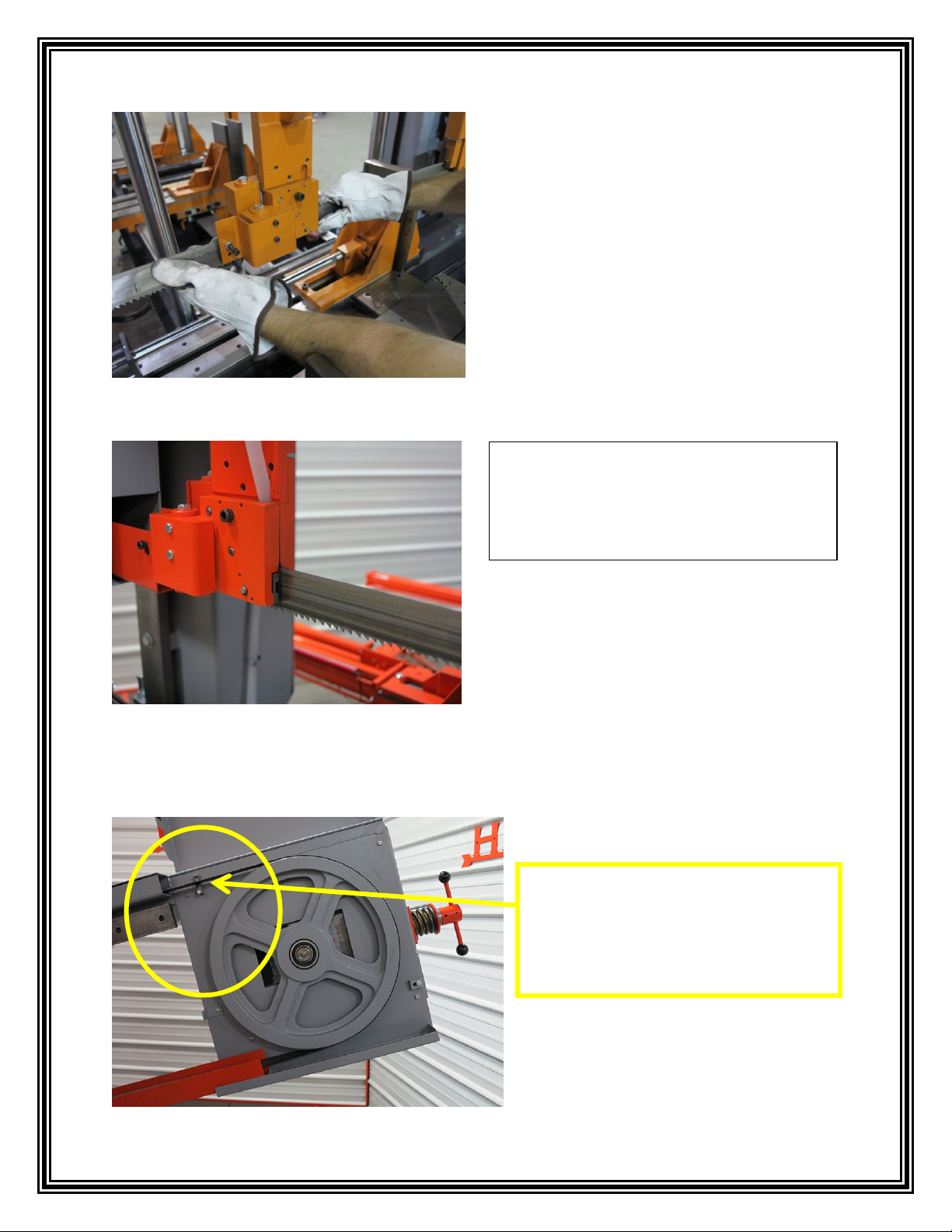
3. Twist the blade into a vertical position and
then insert the blade into the Guide Caps and
between the carbide blade guides. If the Cut
Watcher© feature is present the blade will
have to be maneuvered around that carbide
as well.
NOTE: Make sure the blade is installed
with the teeth pointing down and facing
in the correct direction.
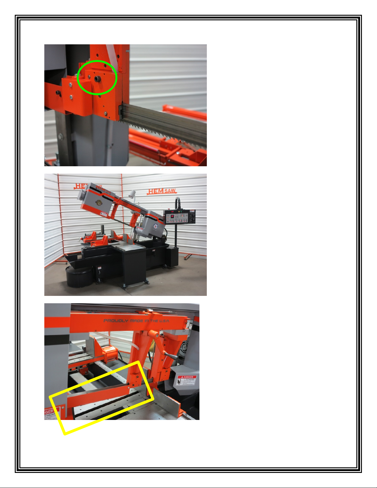
4. Before turning the Blade Tension Handle, make the following checks:
•Make sure the blade is located
properly on the Bumper Block
Carbide near the Idle Wheel.
8
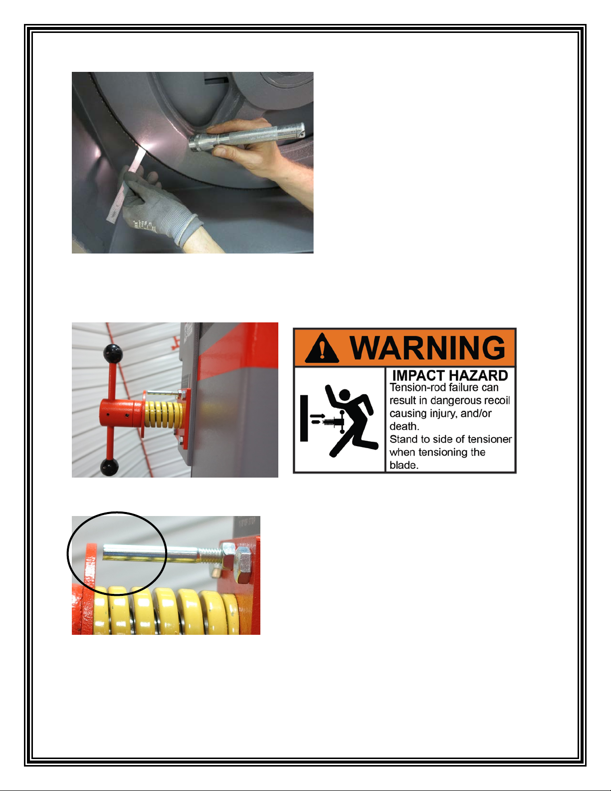
•Check the position of the blade
on the wheels. The teeth of the
blade must NOT touch the
wheel and the blade must NOT
ride on the wheel flanges.
5. Twist the Blade Tension Handle to put tension on the blade. As the blade is tensioned, be
sure to recheck that the blade is still located inside the Bumper Block Carbide.
6. Tension the “T” handle down to within 1/8”
of a flat washer. Do not over-tension the blade.
9
BLADE TENSION CHART
SAW MODEL BLADE TENSION
H90A-1 25,000 PSI
H90A-4 25,000 PSI
H90A-C 25,000 PSI
H105A-4 20,000 PSI
H105A-C 20,000 PSI
H105M 20,000 PSI
H105LA-4 20,000 PSI
H105LA-C 20,000 PSI
H105LM 20,000 PSI
CYCLONE A-4 20,000 PSI
CYCLONE A-C 20,000 PSI
CYCLONE M 20,000 PSI
SIDEWINDER A-1 25,000 PSI
SIDEWINDER A-C 25,000 PSI
SIDEWINDER M 25,000 PSI
7. For saw models with the Optional Air Powered Blade
Tension turn the Blade Tension Knob to tighten the manual
tension till the blade fits snug on the wheels. The Blade
Tension switch will finish the blade tension process.
NOTE: DO NOT over tension the blade with the Blade
Tension Slide Knob. This process is just to make the blade
snug on the wheels.
8. Turn the “Blade Tension” switch to the “ON” position.
This will automatically tension the blade to the proper
setting. After the blade is installed the “Blade Tension”
switch should be left in the “ON” position. NOTE: This
step is ONLY for Saw Models equipped with the
Optional Air Powered Blade Tension.
NOTE: Refer to the Blade Tension Chart to
the left when checking the blade tension
using a blade tension gauge.
10
9. Tighten the blade Guide Caps on
both sides of the saw.
Refer to the Guide Cap Torque
Chart found in the “TIGHTENING
THE GUIDE CAPS” section of this
manual for the correct torque
specifications for this model.
10. Close the wheel covers.
11. Place the Sliding Blade Guard back
into position.

11
12. FOR A-4 AND A-C AIR SAWS: Press the MOTOR “ON”
button and the “Safety Start” on the control panel. The saw has a
self-tracking system that will adjust the blade in or out as the
wheels start rotating. Let the blade run for about 30 seconds, to
allow the blade to track itself on the wheels.
12. FOR MANUAL AIR SAWS: Move the spring-loaded
MOTOR Switch to the “START” position to start the Band Motor.
The saw has a self-tracking system that will adjust the blade in or
out as the wheels start rotating. Let the blade run for about 30
seconds, to allow the blade to track itself on the wheels.
13. FOR MANUAL AIR SAWS: Then place the MOTOR
Switch in the “OFF” position.
12. FOR A-1 AIR SAWS: Move the MOTOR switch on the
control panel to the “ON” position. The saw has a self-tracking
system that will adjust the blade in or out as the wheels start
rotating. Let the blade run for about 30 seconds, to allow the blade
to track itself on the wheels.

12
15. Check the blade brush assembly. Set
the brush to make light contact with the
blade. The wires on the brush should only
sweep through the gullet of the teeth. If the
blade brush is not set properly, it may
cause dulling of the blade on one side and
premature wear of the brush. (Refer to the
“ADJUSTING THE BLADE BRUSH”
section in this manual for additional
information.)
13. FOR A-4 AND A-C AIR SAWS: Then press the MOTOR
“OFF” button.
14. Open the Drive and Idle Wheel Covers and
verify that the blade is still properly located on
the Bumper Block Carbide and the blade is now
in the correct position on the wheel. It is
advisable to recheck the Guide Cap tightness.
13. FOR A-1 AIR SAWS: Move the MOTOR switch to
the “OFF” position.
This manual suits for next models
14
Table of contents
Other HE&M Saw manuals


Popular Saw manuals by other brands


Porter-Cable
Porter-Cable 423MAG instruction manual

Bosch
Bosch GCB 18 V-LI Professional Original instructions

Cengar
Cengar CL50 operating instructions

Bosch
Bosch GCO 14-24 J Original instructions

Parkside
Parkside PAAS 12 A2 Translation of the original instructions

Hitachi
Hitachi C 10FCH2 Handling instructions


