Hafco AL-320G User manual

1
Metal Cutting Lathe
OPERATION MANUAL
Model AL-320G
Page 1
Instructions Manual for AL-320G (L141)
07/02/2018

2
NOTE:
In order to see the type and model of the machine, please see the
specication plate. Usually found on the back of the machine. See
example (Fig.1-1)
Fig.1-1
METAL CUTTING LATHE
MACHINE
AL-320G
MODEL NO.
SERIAL NO.
DATE OF MANF.
NOTE:
This manual is only for your reference. Owing to the continuous improvement of the ma-
chine, changes may be made at any time without obligation or notice. Please ensure the local
voltage is the same as listed on the specication plate before operating this electric machine.
Distributed by
www.machineryhouse.co.nz
MACHINE DETAILS
Page 2
Instructions Manual for AL-320G (L141)
07/02/2018

3
C O N T E N T S:
Safety Precautions...............................................................4
A. Overview of the Machine............................................5
B. Main Usage and Features.............................................5
C. Main Specications........................................................6
D. Transmission System.....................................................7
D.1 Main Transmission System.......................................8
D.2 Feeding System............................................................8
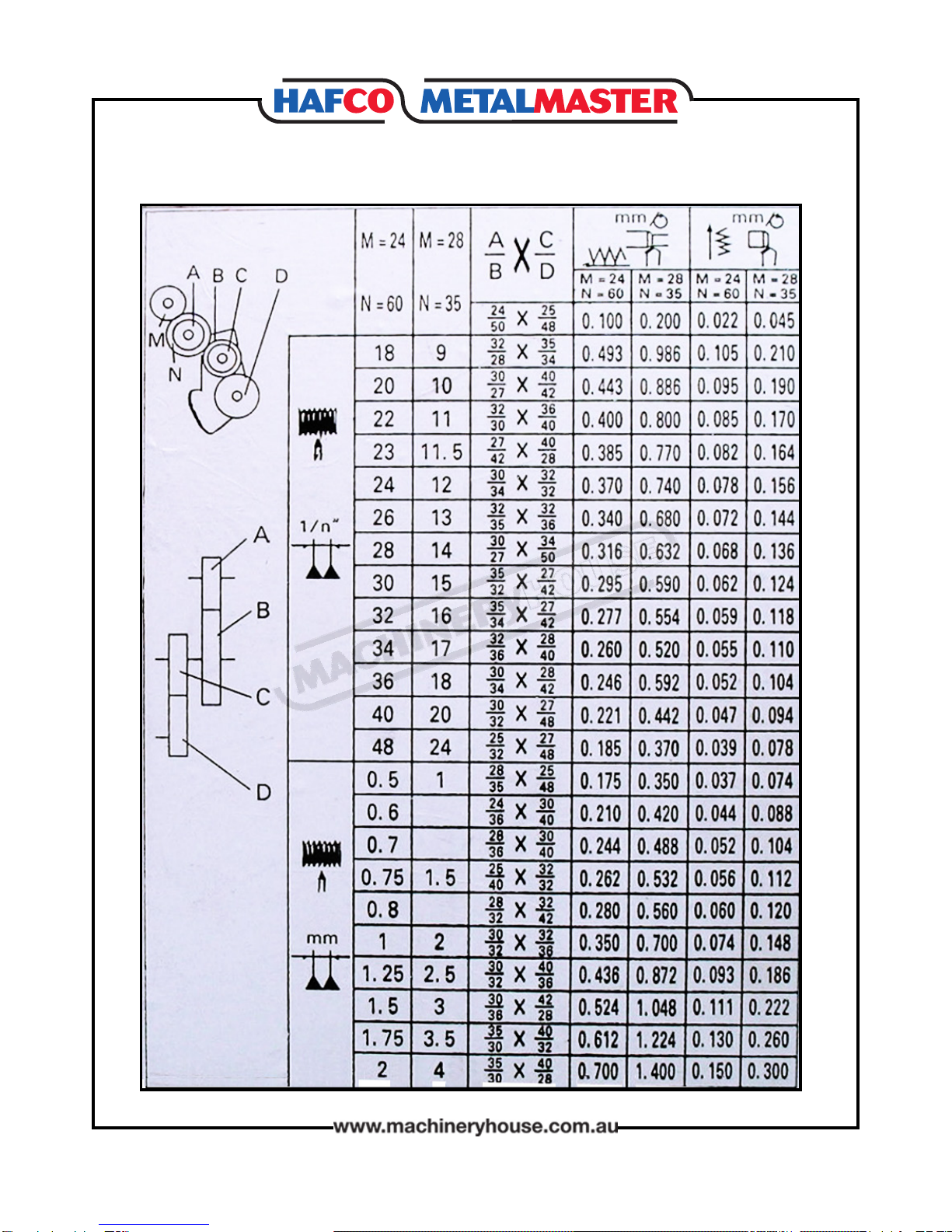
D.2.2 Threading....................................................................9
Change Gears.........................................................9
Thread Chart........................................................10
D2.3 Setting The Cutting Tool With Spindle
Centerline............................................................................11
E. Installation And Adjustment Of The Lathe.........12
E.1 Installation....................................................................12
E.2 Adjustment Of The Lathe........................................13
E.2.1 Adjustment Of Main Spindle..............................13
E.2.2 Adjustment Of Clearance Between The Top
Slide, Worktable And Cross Slide.................................13
E.2.3 The Adjustment Of The Locking Handles Of
TheTailstock........................................................................14
F. Operation.........................................................................15
F.1 Illustration Of The Operation Parts......................15
F.2 Speed Changing Of The Main Spindle...............16
G. Lubrication.....................................................................16
Lubrication Points.............................................................17
Table Of Lubrication Points...........................................17
H. Wiring Diagram.............................................................18
Spare Parts...........................................................................19
Page 3
Instructions Manual for AL-320G (L141)
07/02/2018

4
SAFETY PRECAUTIONS
Safety glasses must be worn at
all times when using the lathe.
Earmus should be worn
when noisy applications are
operating
Gloves must not be worn
when using this machine.
Avoid wearing loose clothes,
rings and loose jewelry
Appropriate footwear with
substantial uppers must be
worn
Do Not operate the machine
until the manual has been
read and understood.
Safety Checks Before Operating
1. Check workspaces and walkways to ensure no slip/trip hazards are present.
2. Locate and ensure you are familiar with the operation of the ON/OFF button
3. Ensure all guards are in place.
4. Check that the job is clamped tight in the chuck.
5. Remove all tools from the bed and slides of the machine.
6. Ensure correct speed for machining process is selected.
7. Remove the chuck key before starting the lathe.
8. Do not try to lift chucks or face plates that are too heavy for you.
9. The lathe should not be used if faulty
Safety Checks While Operating
1. Never leave the lathe running unattended.
2. Before making adjustments or measurements switch o and bring the machine to a
complete stop.
3. Do not attempt to slow/stop the chuck or revolving work by hand.
4. Avoid letting swarf build up on the tool or job. Stop the machine and remove it.
5. Always remove the chuck key from the chuck.
6. Do not store tools and parts on top of the machine.
Potential Hazards
qFlying objects - chuck key left in chuck
qCutting tool injury when cleaning, ling or polishing
qRotating machine parts - entanglement
qMetal splinters/swarf
qEye injuries
Page 4
Instructions Manual for AL-320G (L141)
07/02/2018

5
1. Gear Train Cover
2. Headstock
3. Speed Changing Lever
4. Main Spindle
5. Chuck
6. Steady Rest
7. Toolpost
8. Toolpost Slide
9. Cross Slide
10. Tailstock Sleeve Locking Lever
11. Tailstock
A. OVERVIEW OF THE MACHINE
12. Tailstock Locking Lever
13. Main Switch
14. Forward-reverse Feeding Handle
15. Feeding Box
16. Longitudinal Leadscrew
17. Longitudinal Feeding Hand-Wheel
18. Cross Feed Handle
19. Apron
20. Half-nut Lever
21. Handle for Longitudinal/cross Feeds
22. Bed
B. MAIN USAGE AND FEATURES
The machine is used mainly for the turning, drilling, threading, reaming and knurling, of
metal work pieces.
The machine has excellent features with easy operation. It is suitable for use in small enter-
prises, repair shops, schools and personal hobbies.
Page 5
Instructions Manual for AL-320G (L141)
07/02/2018

6
C. MAIN SPECIFICATIONS
MACHINE
MODEL AL-320
Centre Height 160mm
Max. swing over bed 320mm
Max. length of work piece 600/750mm
Max. swing over cross slide 170mm
Headstock taper MT5
Spindle bore 38mm
Spindle speed steps 6/12
Spindle speed range 60/1600 r.p.m.
TOOLPOST
Max. Cross slide travel 200mm
Max. Top slide travel 100mm
TAILSTOCK
Max barrel travel 80mm
Tailstock taper MT3
THREADS
No. Metric threads 15
No. Inch threads 23
Range of metric threads 0.5-4mm
Range of inch threads 9-48 Threads / Inch
MOTOR
Motor power 750 watts
Voltage 240Volt
Frequency 50Hz
DIMENSIONS Unit packing (LxWxH) cm. 137x70x66
WEIGHT
Net weight 220kgs
Page 6
Instructions Manual for AL-320G (L141)
07/02/2018

7
D. TRANSMISSION SYSTEM
1. Input Pulley
2. Change Gear
3. Change Gear
4. Change Gear
5. Change Gears
6. Output Gears
7. Gears
8. Gears
9. Gears
10. Triple Joined Sliding Gears
11. Gears
12. Spindle Gears
13. Headstock Gears
14. Headstock Gears
15. Duplicate Joined Sliding Gears
16. Top Slide Lead Screw
17. Top Slide Lead Screw Nut
18. Tailstock Lead Screw
19. Tailstock Lead Screw Nut
20. Longitudinal Lead Screw
21. Half-nut for Longitudinal Lead Screw
22. Cross Slide Lead Screw
23. Cross Slide Lead Screw Nut
24. Gears
25. Gears
26. Gears
27. Worm Gears
28. Worm
29. Gears
30. Gears
31. Gears
32. Gears
33. Gears
34. Sliding Gears
35. Gears
36. Motor Pulley
37. Input Shaft
38. Middle Shaft
39. Output Shaft
40. Main spindle
Page 7
Instructions Manual for AL-320G (L141)
07/02/2018

8
D.1 Main Transmission System
Power comes from the motor to the input shaft #37 via input pulley #1, From the input pulley to
main spindle #40 via middle shaft #38. The main spindle has a range of 6 speeds by operating
the speed changing handles on the head stock. (Fig.1) The pulley has two belt positions, and by
changing the belts, the main spindle can achieve 12 speeds.
D.2 FEEDING SYSTEM
D.2.1 The Longitudinal And Cross Feeding Of Toolpost
The Auto Feeding systems is powered from the main spindle through a selection of change
gears, which can be swapped to change the feed rate of the auto feed.
The feed travel direction can be changed with the lever in Fig. 3 with a neutral position in the
middle to stop the rotation of the lead screw shaft. This lever should not be changed while the
spindle is running.
To engage the auto feed use the handle on the carriage. It has three positions, 1 neutral (no
feed engagement), 2 feed to the cross slide or 3 feed to the longitudinal travel. (Fig 2) The
machine feed gears are factory set to A=24, B=50, C=25, D=48, producing 0.100mm per rev-
olution longitudinal travel and 0.022mm per revolution cross travel. This feed step up is rec-
ommended for most general purpose work. If a coarser feed rate is required or for threading
operations please refer to chart on page 10.
NOTE: To reverse the direction of the feed travel, move the lever in the picture below right or
left.(Fig. 4) The lever should not be moved when the spindle is turning (Fig. 3)
Do Not change direction with
the spindle running
Fig. 1
Fig. 3
Fig. 4
Fig. 2
Page 8
Instructions Manual for AL-320G (L141)
07/02/2018

9
When cutting threads, open the door to the change gear box, and check the change gear chart
to select suitable gears to produce the threads required. (the change gears are standard acces-
sories). After the gears are changed, the gear box door must be closed. To engage the thread-
ing mode, the half-nut on the saddle must be engaged through the lever shown in the picture
below. (Fig. 5)When the half nut is engaged the longitudinal and cross feeds are inter-locked
and will only allow one option to operate. The direction of the threading, can be achieved by
switching the direction change shift on the feeding box. (Fig. 3)
D.2.2 Threading
Half Nut Lever Fig. 5
Change Gears
To make changes to the gear train, remove the clips, loosen the T bolt and locking nut on the
pack. Change the necessary gears, replace the clips, and adjust the space backlash between
the gears. Once the backlash has been set then lock the T bolt on the pack. (Fig.6)
Fig.6
Page 9
Instructions Manual for AL-320G (L141)
07/02/2018

10
Thread Chart
Page 10
Instructions Manual for AL-320G (L141)
07/02/2018

11
Fig. 9Fig. 9
4.7 SETTING THE CUTTING TOOL WITH SPINDLE CENTERLINE
The tip of the cutting tool should be set up so that it is in line with the centre line of the spindle,
as illustrated in Fig. 8.
The cutting tool can be raised by placing steel
shims underneath it. The shims should be
as long and as wide as the cutting tool to
properly support it.
There are a number of ways to check that the
cutting tool is on the centre line of the spin-
dle.
Below are two common methods:
• Move the tailstock centre over the cross slide
and use a ne ruler to measure the distance
from the surface of the cross slide to the tip
of the centre. Adjust the cutting tool height so
it is the same distance above the cross slide
as the tailstock centre.
• Align the tip of the cutting tool with a tail-
stock centre, as described in the following
procedure.
1. Mount the cutting tool and secure the post
so the tool faces the tailstock.
2. Install a centre in the tailstock, and position
the tip near the cutting tool.
3. Lock the tailstock and quill in place.
4. Adjust the height of the cutting tool tip to
meet the centre tip, as shown. (Fig.9)
Tailstock Centre
Fig. 8Fig. 8
Page 11
Instructions Manual for AL-320G (L141)
07/02/2018

12
E. INSTALLATION AND ADJUSTMENT OF THE LATHE
When lifting the machine it is recommended that the method used in the diagram below
is used or a fork lift is used. Since there is no obvious hand holding places, please do not lift
or carry the lathe by hand. When lifting the lathe, the use of soft slings or rope should be
used to avoid any damage. To keep the lathe in balance, the carriage and the tailstock
should be moved away from the headstock, to the opposite end of the bed. It is important
to ensure that the tailstock is clamped in order to avoid moving or falling o the end of the
bed. (Fig.6)
Fig. 6
Place the lathe on the Stand, using the four recommended bolts to secure the lathe on the
Stand. The Stand is an optional accessory which can be supplied by your distributor. (Fig. 7)
Fig. 7
E.1 Installation
Page 12
Instructions Manual for AL-320G (L141)
07/02/2018

13
E.2 ADJUSTMENT OF THE LATHE
The main spindle has been adjusted correctly before leaving the factory and you are not re-
quired to make any adjustment. However over the life of the machine it may be necessary to
adjust the spindle to correct the bearing tolerance. If adjustment is required then tighten the
spanner nut until tight then back the nut o half a turn. Ensure that the spindle turns freely. If it
doesn’t then back the nut o until it does. (Fig. 8)
Fig. 8
E.2.2 Adjustment Of Clearance Between The Top Slide, Worktable And Cross Slide
Adjustment points
Adjustment points
Fig. 9
The clearance of the top slide and cross slide have been adjusted before leaving the factory. If
any adjustment is required, please make the change by adjusting the wedges and nuts as per
the instructions shown in the picture below. The clearance is very important for the accuracy
of the lathe. Ensure that the adjustment is not too tight as this could cause the slideway to
wear unevenly making it dicult for the carriage to move; If there is too much clearance in
the slides, this will cause the tool to be pushed away or towards the work piece when taking
a cut and also cause chatter and inaccuracy. After making the adjustment take a trial cut to
determine if the nish cut on the work piece has improved. A magnetic base and dial indi-
cator can also be used to check the lateral movement of the slides. . The places to adjust are
pictured below. (Fig. 9)
E.2.1 Adjustment Of Main Spindle
Page 13
Instructions Manual for AL-320G (L141)
07/02/2018

14
Wedge Two Screws and lock nuts
Fig. 10
Two screws and lock nuts Wedge
Wedge
Nut
Fig. 11
Fig. 12
E.2.3 The Adjustment Of The Locking Handles Of The Tailstock
The locking of the tailstock can be achieved by either the locking nut or locking handle. Ad-
justing the stroke of locking handle can be achieved by adjustment of the nuts. (Fig. 13)
Locking Handle
Locking Nut
Adjusting Nut
Fig. 13
Page 14
Instructions Manual for AL-320G (L141)
07/02/2018

15
F. OPERATION
After assembling the machine, remove the anti-corrosion coating on the slideway, carriage,
toolpost, tailstock and change gears with a clean cloth and kerosene. Once the machine is
clean lubricate the machine as per instructions.
19
F.1 Illustration Of The Operation Parts
1. Socket head cap screw: to open or close the cover of the gear change box
2. Plug: the power lead and plug of the machine
3. Shifting handle: has three positions to adjust the speed.
4. For/Rev handle: has three positions which changes the direction of the tooling travel.
The middle position is neutral.
5. Shifting handle: Has two positions to adjust the speed.
6. Forward/reverse switch: to control the rotation directions of the motor and spindle. It can
be operated only after the motor is stopped.
7 Start button: to start the motor
8. Stop button: to stop the motor
9. Longitudinal hand wheel: to operate the apron longitudinal movement
10. Cross hand wheel: to move the cross slide and toolpost.
11. Toolpost handle for loosing or locking the toolpost
12. Nuts: to x the top slide to the cross slide. This can allow rotation on the topslide.
14. Toolpost hand wheel: to move the topslide and toolpost forward or backward
15. Handle: to control the half-nut for threading
16. Handle: to control the longitudinal and cross auto feeding which has three positions.
18. Lever: to lock the tailstock. The tailstock can be removed or moved freely after loosening.
17. Tailstock Sleeve lock lever. Locks the sleeve in place after moving
19. Tailstock hand wheel: moves the sleeve after the lock lever is loosened.
20. Screw: to adjust the centering position of the tailstock, with the main spindle. Can be
adjusted for taper turning
Page 15
Instructions Manual for AL-320G (L141)
07/02/2018

16
The speed change of the main spindle can be achieved by operating the two speed change
handles on the headstock.
The speed chart shows the positions of the motor pulley changes that are needed to achieve
some range of speeds. (Fig. 15)
Motor Pulley
Positions
Fig. 15
F.3 Threading
See D.2.2
G. LUBRICATION
To keep the machine in good order and prolong the life of the machine, it must be lubricated
with SAE 20 mechanical oil as per the lubrication instruction below.
Splash lubrication is used inside the headstock and cup-lling lubrication for other points.
To change the headstock oil, remove the oil and clean the inside of the headstock with a clean
cloth. Then ll with clean lubricating oil.
After the machining operation is nished, the surfaces of the slideways must be cleaned and
the swarf removed. The slides should then be covered with oil.
a. Recommend to use Grease #3 as listed in table of lubrication positions (Fig. 17)
b. Recommend to use Oil #20 as listed in the table of lubrication positions (Fig. 17)
c. Regularly, the lubricated parts should be cleaned and the oil in the feeding box should be
changed and relled to the center line of the oil window.
F.2 Speed Changing Of The Main Spindle
Page 16
Instructions Manual for AL-320G (L141)
07/02/2018

17
Lubrication Points
Table Of Lubrication Points
Fig. 16
Page 17
Instructions Manual for AL-320G (L141)
07/02/2018

18
H. Wiring Diagram
Fig. 17
The maintenance of the electrical parts, and wiring must be made by a qualied electrician.
Wiring Colour Code.
Yellow/Green wire --- Grounding
Blue wire --- Neutral
Brown --- Live
Cautions:
If the motor does not work while the power voltage is on, rst check the cut-out units.
E.G. check if the micro switch has been closed properly inside the change gear box.
Page 18
Instructions Manual for AL-320G (L141)
07/02/2018

19
SPARE PARTS SECTION
The following section covers the spare parts diagrams and lists that were current at the time
this manual was originally printed. Due to continuous improvements of the machine, changes
may be made at any time without notication.
HOW TO ORDER SPARE PARTS
1. Have your machines Model Number, Serial Number & Date of Manufacture on hand,
these can be found on the specication plate mounted on the machine
2. A scanned copy of your parts list/diagram with required spare part/s identied
3. Go to www.machineryhouse.com.au/contactus and ll out the enquiry form attaching a
copy of scanned parts list.
CONTENTS
AL-320 Bed Parts..................................................................20
AL-320 Bed Parts List..........................................................21
AL-320 Headstock Parts.....................................................23
AL-320 Headstock Parts. List............................................24
AL-320 Back Gear Parts......................................................27
AL-320 Back Gear Parts.List..............................................28
AL-320 Gearbox Parts.........................................................30
AL-320 Gearbox Parts List.................................................31
AL-320 Apron Parts.............................................................32
AL-320 Apron Parts List.....................................................34
AL-320 Compound Slide Parts........................................36
AL-320 Compound Slide Parts List................................37
AL-320 Tailstock Parts.........................................................38
AL-320 Tailstock Parts List.................................................39
Risk Assesment Sheet.........................................................40
Page 19
Instructions Manual for AL-320G (L141)
07/02/2018

20
AL-320 BED PARTS
Page 20
Instructions Manual for AL-320G (L141)
07/02/2018
This manual suits for next models
1
Table of contents
Other Hafco Lathe manuals
Popular Lathe manuals by other brands

Proxxon
Proxxon PD 230E Manual guide

Robust
Robust Sweet Sixteen owner's manual

Jean Lebeniste
Jean Lebeniste MC1100B instruction manual

Little Machine Shop
Little Machine Shop Mini Lathe user guide

Gude
Gude GDM 1000 Translation of original operating instructions

Pilous
Pilous ARG 250 S.A.F. instruction manual

Ray Foster
Ray Foster PR75 instruction manual

Jet
Jet BDB-919 Operating instructions and parts manual

Gude
Gude GMD 400 Translation of original operating instructions

Jet
Jet JML-1014VSI brochure

Craftsman
Craftsman 113.23881 Operating instructions and parts list

mori seiki
mori seiki MSC-500 Maintenance manual