Hafler VRM 15SCE User manual

®
VRM10S
VRM10SCE
VRM12S
VRM12SCE
VRM15S
VRM15SCE
SUBWOOFER
SYSTEMS

Declaration of Conformity
Application of Council Directive: 73/23/EEC (Low Voltage Directive)
89/336/EEC (EMC Directive)
Standard(s) to which Conformity is Declared: EN55103-1
EN55103-2
EN60065
Manufacturer’s Name: Hafler
Manufacturer’s Address: 546 South Rockford Drive, Tempe, Arizona 85281
Importer’s Name:
Importer’s Address:
Type of Equipment: Amplified Subwoofer
Model No: VRM10sCE VRM12sCE VRM15sCE
Year of Manufacturing: 1999 2000 2001 2002 2003
Serial Number:
I,theundersigned,herebydeclarethattheequipmentspecifiedaboveconforms
totheaboveDirective(s)andStandard(s)
Place: Hafler
Date: 12/01/98 James C. Strickland, VP Engineering

– i –
25Hz-100Hz, ±2dB
>115dB (w/music @ 2m)
<3%, 25Hz (90dB @ 2m)
12” (305mm) Cellulose Fibre Cone
Santoprene Rubber Surround
2.5” (63.5mm) 4-Layer Voice Coil
102 oz. Magnet
1.8ft3(50.4Liter) Bass Reflex Down Firing
16.75”(H) x 18.50”(W) x 19.50”(D)
(46.35cm x 49.53cm x 49.21cm)
Black Ebony Ash Vinyl
74 lbs. (33.6kg)
Free Field Frequency Response
Peak Acoustic Output
Total Harmonic Distortion (THD)
Low Frequency Driver
Dimensions
Cabinet Finish
Net Weight
27Hz-100Hz, ±2dB
>112dB (w/music @ 2m)
<3%, 30Hz (90dB @ 2m)
10”(254mm) Cellulose Fibre Cone
Santoprene Rubber Surround
2”(51mm) 4-Layer Voice Coil
30 oz. Magnet
1.0ft3(28 Liter) Bass Reflex Down Firing
14.75”(H) x 16.0”(W) x 17.50”(D)
(37.46cm x 40.64cm x 40.64cm)
Black Ebony Ash Vinyl
51 lbs. (23.2kg)
SUBWOOFER MODEL VRM10S VRM12S
22Hz-100Hz, ±2dB
>118dB (w/music @ 2m)
<3%, 22Hz (90dB @ 2m)
15”(381mm) Cellulose Fibre Cone
Santoprene Rubber Surround
2.5”(63.5mm) 4-Layer Voice Coil
153 oz. Magnet
2.5ft3(70 Liter) Bass Reflex Down Firing
18.75”(H) x 20.0”(W) x 21.0”(D)
(46.35cm x 49.53cm x 49.21cm)
Black Ebony Ash Vinyl
88 lbs. (40kg)
VRM15S
Frequency Response @ 2m* Frequency Response @ 2m*
VRM10s
Frequency Response
Specifications are subject to change without notice.
Performance Specifications
VRM12s
Frequency Response VRM15s
Frequency Response
Frequency Response @ 2m*

–ii –
Power Rating
Signal-to-Noise
CMRR
Input Impedance
Input Sensitivity Range
Maximum Input
Gain
Crossover Frequency Variable from 40Hz~140Hz
Crossover Slope 24dB/octave (4th order) Linkwitz-Riley
Subsonic Filter 12dB/octave (-3dB @ 18Hz)
Specifications are subject to change without notice.
Idle Power: 11W / 150mA @ 120 VAC
Idle Power: 11W / 90mA @ 230 VAC
Normal Operation: 66W / 380mA @ 230VAC
Full Power: 330W / 3.3A @ 120VAC
Full Power: 315W / 1.7mA @ 230VAC
Unbalanced RCA Inputs
Gain Control (30dB range)
Low Pass Crossover (variable 40Hz~140Hz)
Phase DIP Switches (0°, -90°, -180°, -270°)
200W RMS @ 4 ohms
>100dB
>70dB typical @ 60Hz
47kΩper phase balanced, 47kΩunbalanced
RCA Input: 160mV to 5V RMS
Speaker Input: 50mV to 45W (receivers that
drive nominal 8Ωspeaker loads)
RCA Input: 10V RMS
Speaker Input: 180W (receivers that drive
nominal 8Ωspeaker loads)
+45dB max. to +15dB min.
Performance Specifications - Amplifier Section
Power Consumption
Rear Panel
Low -Pass Crossover Section

–iii –
PERFORMANCE SPECIFICATIONS
Frequency Response Graphs i
INTRODUCTION 1
TECHNICAL DESIGN FEATURES 1
DESIGN FEATURES 4
INSTALLATION
Location 5
Typical Studio Installations 5
Home Theater Installations 5
Input Switch 6
XLR Wiring Configurations 7
OPERATION
Auto Turn-On/Sleep Mode 8
Input Sensitivity 8
Low-Pass Crossover 8
Phase Control 9
Set-up Procedure 9
AC Line 10
LED Indicator 10
Break-In and Warm Up 10
Cleaning and Maintenance 10
SERVICE POLICY &LIMITED WARRANTY 11
SAFETY PRECAUTIONS 12
Table of Contents

–1 –
The VRM10s/VRM12s/VRM15s monitors utilize a specially designed amplifier featuring our innova-
tive Trans•ana circuitry. This topology, with its unique input-to-output configuration (derived from
our patented Trans•nova circuit), employs power gain in the MOSFET output stage that result in
superior sound quality.
The amplifier features an auto turn-on/off circuit that eliminates the need for a conventional power
switch. Input signals can be fed into the amplifier via Un-Balanced RCA jacks or Speaker level input
jacks. Each pair of inputs is combined into a mono-summed signal before being fed into a 4th order
Linkwitz-Riley low-pass crossover, adjustable from 40Hz~140Hz. If selected, the signal is then fed
into the Phase Control that allows the phase of the signal to be adjusted at 90˚, 180˚, or 270˚incre-
ments.
The VRM10s is a 10”(254mm) low frequency transducer that features a 2”(51mm) voice coil and is
driven by a 30 oz. magnet. The VRM12s is a 12”(305mm) low frequency transducer that features a
2.5”(63.5mm) voice coil and is driven by a 102 oz. magnet. The VRM15s is a 15”(381mm) low fre-
quency transducer that features a 2.5”(63.5mm) voice coil and is driven by a 153 oz. magnet. All
VRM transducers feature Cellulose Fiber cones for accurate sound reproduction and Santoprene
Rubber Surrounds that are immune to temperature fluctuations. This specialized rubber surround
controls woofer damping and reduces 2nd harmonic distortions for a very wide and flat frequency
response. The VRM series voice coils are 4-layers of copper wound on aluminum formers.
Aluminum voice coil formers provide excellent heat dissipation that provides higher power handling
versus plastic or Kapton type formers used by other manufacturers.
Introduction
Technical Design Features
Thank you and congratulations on your purchase of the HAFLER series of Subwoofer, the world's
finest brand in professional audio equipment.
The VRM series is comprised of three modules; the VRM10s, VRM12s, and VRM15s. The VRM10s
is an amplified 10" subwoofer. The VRM12s is an amplified 12" subwoofer and the VRM15s is an
amplified 15" subwoofer. All VRM series are designed and engineered for Home Theater Systems.
For ease of use, this manual is organized into two main sections: Installation and Operation.
"Installation" covers the set-up of your new HAFLER equipment in the system. "Operation" covers
the controls and how to use them for optimum performance.

–2 –
MEHSA
(Maximum Efficiency HeatSink Application) MEHSA is a proprietary process that yields up to 5 times
better heat transfer than traditional FET mounting techniques using the exact same components. A
multi-layer insulated metal substrate operating with minimal thermal resistance spreads heat both
downward and outward to quickly dissipate heat from each device across the heatsink. This process
combined with our DSM technology and MOSFET devices allows us to squeeze more watts per cubic
inch from every output device as well as provide consistent thermal stability.
The Result: Better reliability through faster heat dissipation.
Trans•ana
Trans•ana (TRANSconductance Active Nodal Amplifier) is a circuit that allows the audio signal to pass
through the amplifier at low voltage. The signal is directly level-shifted to the fixed high voltage rails
via a pair of driver transistors. Signal linearity is assured by an active node formed by the driver transis-
tors at ultrasonic frequencies. This allows amplifier performance similar to Trans•nova which is highly
stable and linear while utilizing the advantages of a non-floating power supply.
The Result: An extended frequency band width accurately supplied to the output stages of the
amplifier.
MOSFET Devices
HAFLER is one of the few manufacturers in the sound community to utilize MOSFET devices in the
amplifier output stage. MOSFET (Metal Oxide Semiconductor Field Effect Transistor) devices offer sev-
eral important inherent advantages over older bi-polar designs. These advantages include: thermal sta-
bility, fast switching speed, ultra low output impedance and wide bandwidth linearity. In addition,
MOSFETs operate very similarly to vacuum tubes in that they are more linear than bipolar transistors.
However, MOSFETs can deliver the midrange clarity without the limitations of transient response and
high frequency phase shifting normally associated with tube
operation.
The Result: Thermal stability, fast switching speed, ultra low output impedance and wide bandwidth
linearity.
Heat Monster:
High output MOSFET device
Solder
Copper heat spreader
Dielectric layer
Base Layer - aluminum
Thermal grease
Heat sink
Screw, no pressure on component!
Multiple heat paths PC Board
Clamp Bar
Heat generating component
(typically a power MOSFET or
bipolar semiconductor)
Thermal grease
Mica
Thermal grease
Heat sink
Screw
Heat path PC Board
The MEHSA Way The Old Way
Technical Design Features

–3 –
Subsonic Filter
The VRM series uses a Subsonic Filter to prevent the woofer from reproducing inaudible frequencies.
Subsonic frequencies (known as infrasonic frequencies) are signals below the normal human hearing
range.The subsonic filter reduces the energy of these frequencies and restrains the woofer from operat-
ing outside its optimum linear excursion. This type of electronic control eliminates the mechanical dis-
tortion caused by a woofer traveling beyond its XMAX, improves power handling, increases reliability
and improves sonic performance.
The Result: Improved power handling, increased reliability and improved sonic performance.
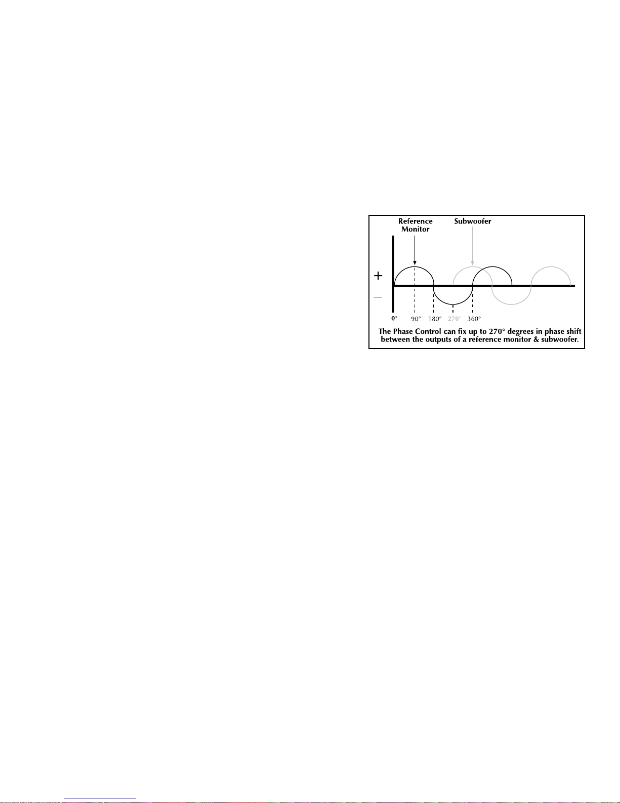
Phase Control
The Phase Control is used to align the arrival time of the sub-
woofer’s output information with satellite monitors. Aligning
both signals will insure that both Subwoofer and reference
monitor information arrive at the listening position at the same
time. This eliminates the possibility of acoustical cancellation
and improves the reproduction of transients in the crossover
region.
The Result: Eliminates phase cancellation and improves tran-
sient response.
Speaker Level Inputs
Does your receiver have only speaker level outputs? No problem! Hafler’s Speaker Level Input circuitry
converts the speaker line outputs (high level) from your receiver into pre-amp line inputs (low level) for
your VRM amplifier. This allows compatibility with a variety of receivers as well as the ability to retrofit
your new Hafler subwoofer into existing systems without the need for external adapters.
Santoprene Rubber Surround
Santoprene is a very durable and temperature tolerant material which provides a consistent support
necessary for the linear motion of the speaker cone. In addition, the damping capabilities eliminate
the transmission of sonic disturbances between the cone and the frame of the speaker. This greatly
improves the accuracy of the woofer’s low frequency response.
The Result: Improves woofer’s low frequency response.
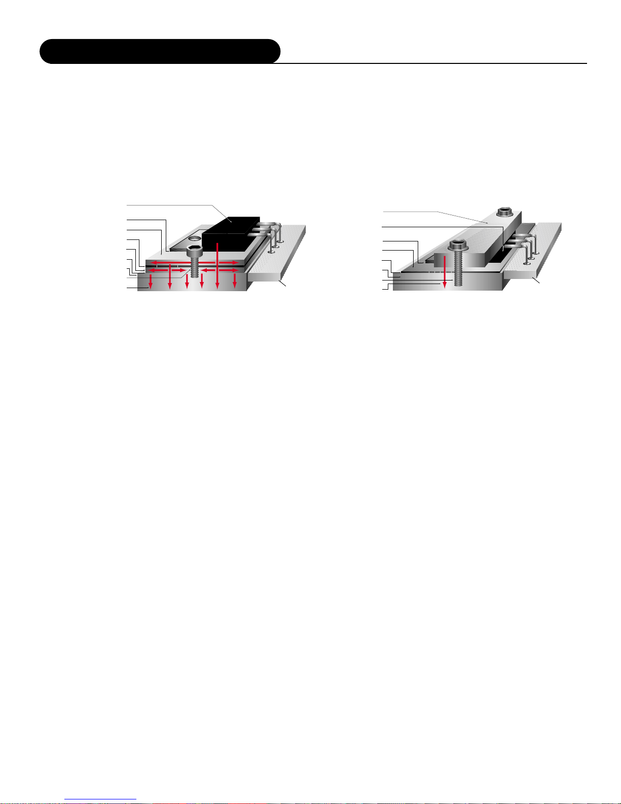
Aluminum Voice Coil Former
The transducers voice coil former is black anodized aluminum for highly efficient thermal transfer.
Another method of producing voice coils is with Kapton®formers. Although this material is very resis-
tant to heat, any heat generated by the transducer is “trapped”on the copper voice coil windings.
HAFLER uses aluminum voice coil formers because aluminum acts like a “heat sink”and helps dissi-
pate heat away from the voice coil. This allows winding high temperature copper wire in multiple lay-
ers for improved efficiency.
The Result: Improves power handling by efficiently dissipating heat.

–4 –
1. RCA Input/Speaker Level Input Switch
2. Gain Control
3. RCA Input
4. RCA Output (full range)
5. Speaker Line Input
6. Speaker Line Output (Full range)
7. Low-Pass Crossover
8. Phase Switches
9. Enclosure Vent
10. AC Line Input
11. AC Line Fuse
41
23
5
6
7
8
9
10 11
1
Design Features

Home Theater Installations
Home Theater installations are typically medi-
um sized living rooms or game rooms that
have large flat, uncovered walls. Acoustics in
this type of installation can have a big effect
on the SPL (Sound Pressure Level) and f3 (low
frequency cut-off) of the subwoofer because
the walls are very reflective. The only ele-
ments in these installations that acoustically
“absorb”sounds are furniture and carpet.
Dramatic “Boundary Loading”can be
achieved by locating the subwoofer under a
table, next to a wall or in a corner (FIG. 4),
thus increasing SPL and lowering the f3 of the
subwoofer system. Locating the subwoofer in
the middle of the room or in a large open area
where there are few reflective surfaces will
cause a decrease in SPL and an increase in f3.
Experiment with different locations in the
room to determine which type of bass response works best in your home theater.
–5 –
Listening Area
Left
Front Right
Front
Center
Front
Right
Rear
Left
Rear
Subwoofer
Location
The size of the room used for your Home Theater can have a significant effect on the bass response of
your system. Since many movies exaggerate explosions, earthquakes, and other low frequency effects,
a high performance subwoofer system is required. Your Hafler subwoofer is specially designed for
these high levels of excursion and linearity. In order to get the most out of your subwoofer, Hafler has
documented the differences between typical Studio and Home Theater installations.
Typical Studio Installations
In typical studio installations, damping material is usually used on the walls and ceilings make the
room “acoustically dead." In this type of anechoic environment, the subwoofer will tend to experience
minimal “Boundary Loading”effects. Firing the subwoofer downward (FIG. 1) or directly facing for-
ward (FIG. 2) and keeping the cabinet at least 5”(12.7 cm) away from any wall will provide best
results.
FIG. 1
Downward Firing FIG. 2
Forward Firing
Keep subwoofer enclosure 5”
(12.7 cm) from any wall
Installation

–6 –
+ -
+ -
Speaker Level Outputs
VRM Subwoofer
VRM Satellite Speaker VRM Satellite Speaker
Receiver
Installation

–7 –
Installation using RCA (low level) Inputs
Receiver
VRM Subwoofer
Signal Level Output
Signal Level Loop (SLL)
Shown here passing low-level signal to an optional
component such as signal processor or an additional
Hafler VRM Subwoofer.

–8 –
*This graph was generated by setting the variable crossover to 40Hz
50Hz, 60Hz, 70Hz, 80Hz, 90Hz, 100Hz, 120Hz & 140Hz.
Auto Turn-on / Sleep Mode
The VRM subwoofers automatically turn on when they sense an input signal. When the signal being
fed to the VRM is turned off, the subwoofer’s amplifier will turn off and go into “sleep mode.”This
feature eliminates the inconvenience of operating a mechanical power switch.
Input Sensitivity
The Input Sensitivity is used to match the VRM series with signal levels from a variety of signal
sources. The Input Sensitivity uses a potentiometer to match input levels over a 30dB range and is
variable from 0dB to -30dB. The numbers listed on the back panel indicate attenuation from maxi-
mum gain, calibrated in dB.
Low-Pass Crossover
The Low-Pass Crossover is used to set the electrical cutoff point of the subwoofer enclosure. The
Crossover uses a variable potentiometer to set the cutoff point anywhere between 40Hz and 140Hz.
When the control is set to its full CLOCKWISE posi-
tion the cutoff frequency is set to 140Hz Low-Pass.
When the control is set to its full COUNTER CLOCK-
WISE position the cutoff frequency is set to 40Hz
Low-Pass.
It is important to match the Low-Pass crossover point
of the subwoofer with the High-Pass crossover point
of the high frequency reference monitors.
Mismatching the crossover points can cause dips or
peaks in the acoustical response. Overlapping the
crossover points (i.e., subwoofer at 60Hz Low-Pass &
high frequency monitors at 50Hz High-Pass) can
cause a peak between 50Hz and 60Hz.
Underlapping the crossover points (i.e., subwoofer at
40Hz Low-Pass & high frequency monitors at 70Hz
High-Pass) will cause a dip between 40Hz and 70Hz.
We recommend using a crossover setting whenever
possible to minimize “localization”of the subwoofer,
usually between 50Hz and 60Hz. These low frequen-
cies make it nearly impossible to detect where the
subwoofer is in the listening room.
Operation
Electrical Crossover Response*
50
60 70 80
90
100
120
140
40HZ
Low Pass
50
60 70 80
90
100
120
140
40HZ
Low Pass

–9 –
Phase Control
The Phase Control switches allow the VRM subwoofer to be acoustically aligned with other speakers in
your system. 0˚, -90˚, -180˚, or -270˚degrees of phase shift at 80Hz can be selected using DIP switch-
es 2, 3, and 4. For 0˚degrees of phase shift, leave all three switches in the OFF (up) position. –270˚
degrees of phase shift occurs when switch 2 is selected in the ON (down) position. –180˚degrees can
be achieved by selecting both switches 2 and 3 in the ON (down) position. Finally, selecting all
switches 2, 3, and 4 in the ON (down) position produces –90˚degrees of phase shift.
Set-up Procedure
1) Place all your speakers and any acoustically significant components in their working location in the
listening environment.
2) Insert a sine wave signal into the audio path. Be careful to turn down the level before turning on
the amplifiers.
3) Choose a frequency that corresponds to the crossover frequency between the VRM subwoofer and
the reference monitors.
4) From the listening position, alternate between the VRM subwoofer and the full range speakers and
adjust the levels until they have the same acoustic output. Use an SPL meter, a microphone on a VU
meter, or your ears to accomplish this.
5) With all speakers on, try the 0˚, -270˚, -180˚, and –90˚degree phase settings. The setting with the
highest SPL reading from your listening position will produce the most effective acoustic alignment.
6) Set the VRM10s/VRM12s/VRM15s gain control according to your preference. This will not affect the
acoustic alignment of your system.
Here is a list of some items that can affect acoustic alignment: Relocating speakers, changing the VRM
subwoofer Low Pass frequency, changing the acoustic environment (i.e., traps, diffusers, etc.), changing
the listening position.
Although this procedure produces the maximum achievable acoustic gain for your system, listening
tests may still lead you to prefer another setup.
Example of how phase misalignment between high frequency speakers and a subwoofer can cause
cancellation
Operation

–10 –
AC Line
The VRM10s/VRM12s/VRM15s operate from a 115 VAC/60Hz power line.
The VRM10sCE/VRM12sCE/VRM15sCE operate from a 230 VAC 50/60Hz power line. Connection is
made by a 16 gauge, IEC Type 320, grounded line cord. For safety considerations only a properly
grounded (earthed) receptacle should be used. If a grounded circuit is not available, do not break off
the ground pin; use the proper adapter plug for a two wire receptacle with the grounding plug suitably
connected to earth ground.
Important: The power line fuse is mounted on the rear panel. If this fuse blows, replace it only with
the same type and rating as indicated in the parts list.
LED Indicator
Amplifier operation is monitored internally and has a
status LED. This indicator can be used for system
troubleshooting. The LED will illuminate GREEN if
signal is present at the subwoofer’s input. The LED will
turn off and the amplifier will go into sleep mode if
signal is not present.
Break-in and Warm-up
We recommend initially breaking in the subwoofer for approximately 8 hours with musical information
to establish the subwoofer’s natural bass response.
Cleaning & Maintenance
There is no requirement for regular maintenance on the electronic components of the subwoofer. If the
cabinet or woofer becomes soiled, it can be cleaned using a damp, soft cloth. If the subwoofer is locat-
ed in a particularly dusty environment, cleaning the inside with compressed air or vacuuming every 18
to 24 months is sufficient.
COLOR STATUS
GREEN Power on
NO LED Sleep Mode

–11 –
Rockford Corporation (Hafler Division) offers a limited warranty on Hafler products on the following
terms:
•Length of Warranty
1 year on Subwoofer Monitors
•What is Covered
This warranty applies only to products sold to the original owner and is non-transferable. This
warranty only applies to units sold in the continental United States. You are required to have a
copy of the receipt stating the customer’s name, dealer name, product purchased and date of
purchase.
•Products found to be defective during the warranty period will be repaired or replaced (with
product deemed to be equivalent) at Hafler’s discretion.
•What is NOT Covered
1. Damage caused by accident, abuse, improper operations, water, theft
2. Service performed by anyone other than Hafler or an Authorized Hafler service center
3. Any product purchased outside the United States (please contact your local dealer)
4. Shipping charges to get the unit to Hafler
5. Any product which has had the serial number defaced, altered, or removed
•Limit on Implied Warranties
Any implied warranties including warranties of fitness for use and merchantability are limited in
duration to the period of the express warranty set forth above. Some states do not allow
limitations on the length of an implied warranty, so this limitation may not apply. No person is
authorized to assume for Hafler any other liability in connection with the sale of the product.
•How to obtain service or technical support
Please call 1-800-669-9899 for Rockford/Hafler support. You must obtain an RA # (return
authorization number) to return any products to Hafler. You are responsible for shipment of
product to Hafler.
Rockford Corporation
Hafler Division
2055 E. 5th Street
Tempe, Arizona 85281
Service Policy and LimitedWarranty

–12 –
The lightning flash with arrowhead symbol within an equilateral triangle is
intended to alert the user to the presence of uninsulated “dangerous volt-
age”within the product’s enclosure, that may be of sufficient magnitude to
constitute a risk of electric shock to persons.
The exclamation point within an equilateral triangle is intended to alert the
user of the presence of important operating and maintenance (servicing)
instructions in the literature accompanying the appliance.
1.Read Instructions
All the safety and operating instructions of your Hafler equip
ment should be read before power is applied to the equipment.
2.Retain Owner’s Manual
These safety and operating instructions should be retained for
future reference.
3.HEED WARNINGS
All warnings on the equipment and in the operating instructions
are important and should be followed.
4.FOLLOW INSTRUCTIONS
All operating and use instructions are important and should be fol-
lowed.
5.HEAT
The equipment should be kept away from areas of high tempera-
ture, i.e., heater vents, radiators, stoves/ovens, fireplaces, etc.
6.VENTILATION
The equipment should be used in an area suitable for proper ven-
tilation. Care should be taken not to impede airflow in and
around the cabinet.
7.WATER AND MOISTURE
The equipment should not be used in or around water, such as a
bathtub, sink, or swimming area. Also, the equipment should not
be used in areas prone to flooding, such as a basement.
8.POWER SOURCES
The equipment should be connected only to a power source of
the same voltage and frequency as that listed on the rear panel
above the power cord entry point.
9.POWER CORD PROTECTION
Power cords should be arranged so they do not interfere with the
movement of objects in the room: people, fan blades, utility carts,
etc. Also, care should be taken that the cord is not pinched or
cut, and placed so it is not in danger of being pinched or cut, as
in under a rug, around a tight corner, etc.
10.POWER CORD GROUNDING
The power supply cord is of a three wire grounded type, designed
to reduce the risk of electric shock sustained from a live cabinet.
It is assumed to be of suitable length for most uses of the equip-
ment. The use of extension cords and power strips is discouraged
unless they are of suitable rating to deliver the required total cur-
rent for safe operation of all connected equipment. Furthermore,
extension cords or power strips must provide the same three wire
grounded connection. It is important that the blades of the equip-
ment’s plug be able to fully insert into the mating receptacle.
Never remove the round grounding pin on the plug in an attempt
to mate to a two wire ungrounded receptacle: use a grounding
adapter with the grounding tab or wire suitably connected to earth
ground.
11.NON-USE PERIODS
During periods of extended non-use, the power cord should be
unplugged from the power source.
12..CLEANING
The equipment should be cleaned only as detailed in the operat-
ing instructions.
13..OBJECT AND LIQUID ENTRY
Care should be taken so that objects and/or liquids, such as clean-
ing fluids or beverages, are not spilled into the enclosure of the
equipment.
14..DAMAGE REQUIRING SERVICE
Hafler equipment should be serviced by qualified service person-
nel when:
A.The power supply cord or plug has been damaged, or
B.Objects have fallen onto, or liquid has been spilled into the
equipment, or
C.The equipment has been exposed to rain, or
D.The equipment does not appear to operate normally or
exhibits a marked change in performance, or
E.The equipment has been dropped, or the enclosure has
been damaged.
15.SERVICING
The user should not attempt to service the equipment beyond that
which is described in the operating instructions. All other service
should be referred to qualified service personnel.
16.CARTS AND STANDS
The equipment should be used with carts or stands only of suffi-
cient strength and stability for the use intended.
An equipment and cart combination should be moved
with care. Quick stops and starts, excessive force, and uneven sur-
faces may cause the equipment and cart combination to topple.
NOTICE - IMPORTANT SAFETY INFORMATION
CAUTION
RISK OF ELECTRIC SHOCK
DO NOT OPEN
WARNING:
TO PREVENT FIRE OR SHOCK HAZARD
DO NOT EXPOSE THIS EQUIPMENT TO RAIN OR MOISTURE.
!

–13 –
1.LEA LAS INSTRUCCIONES
Todas las instrucciones de seguidad y operación de su equipo
Hafler, deben ser leídas antes de que el equipo sea conectado
dléctricamente.
2.CONSERVE EL MANUAL DEL PROPIETARIO
Estas instrucciones de seguridad y operación, deben ser conser-
vadas para futuras referencias.
3.CUADROS DE ADVERTENCIAS
Todas las advertencias en el equipo y en las instrucciones de
operación, son importantes y deben ser seguidas.
4.SIGA LAS INSTRUCCIONES
Todas las instrucciones de uso y operación son importantes y
deben ser seguidas.
5.CALOR
El equipo debe ser mantenido lejos de areas de alta temperatura,
como por ejemplo: ventilaciones de calentadores, radiadores, est-
ufas/hornos, hogueras, etc.
6.VENTILACION
El equip debe ser usado en áreas con ventilación adecuada.
Deben er tornadas las precauciones necesarias para no impedir el
flujo de aire dentro y alrededor del aparato.
7.AGUA Y HUMEDAD
El equipo no debe ser usado en el agua óalrededor de ésta, tales
como en una bañera, tanque o áreas de nado. También, el equipo
no debe ser usado en áreas propensas a inundaciones, tales como
en un sótano.
8.FUENTES DE PODER
El equipo debe ser conectado a una fuente de poder del mismo
voltaje y frecuencia que el indicado en el panel trasero sobre el
punto de entrada del cable de corriente.
9.PROTECCION DEL CABLE DE CORRIENTE
Los cables de corriente deben ser dispuestos de forma tal que no
interfieran con el movimiento de objetos en la sala: personas,
aspas de ventilación, carretillas, etc. También, es necesario tener
cuidado de que el cable no estépunzado o cortado, y debe estar
ubicado de forma tal que esto no ocurra, como podría suceder
debajo de una alfombra o al pasar el cable por una esquina
aguda, etc.
10.ATERRAMIENTO DEL CABLE DE CORRIENTE
El cable de corriente es del tipo aterrado de tres hilos, diseñado
para reducir el riesgo de una descarga eléctrica procendent de un
chasis energizado. Se asume que su longitud es suficiente para la
mayoría de usos del equipo. El uso de extensiones y multi-
enchufes no es recomendado, a menos que tengan el amperaje
adecuado para poder suministrar la corrioente requerida pra la
operación segura de todo el equipo conectado. Aun más, las
extensiones deben proveer de la misma conección aterrada de tres
hiles. Es importante que el enchufe se pueda introducir completa-
mente en el receptáculo. Nunca remeva el pin de aterramiento en
un intento por conectar el cable en un receptáculo de dos hilos
no aterrado: use un adaptador de aterramiento que estéadecuada-
mente conectado a un punto de tierra.
11.PERIODOS SIN USO
Durante períodos prolongados sin uso del equipo, el cable de cor-
riente debe ser desconectado de la fuente de electrixidad.
12..LIMPIEZA
El equip debe ser limpiado solo en la forma que se detalla en las
instrucciones de operación.
13..INTRODUCCIÓN DE OBJETOS Y LIQUIDO
Deben ser tornadas precauciones con el fin de que objetos y/ó
líquidos, tales como fluidos de limpieza y gaseosas, no sean derra-
mados dentro del chassis del aparato.
14.DAÑOS QUE REQUIEREN DE SERVICIO
Los equipos Hafler deben ser llevados a servicio por personal cali-
ficado cuando:
A.El cable de corriente óel enchufe haya sido
dañado, ó
B.Objetos ólíquido hayan sido introducidos óder
ramado en el equipo, ó
C.El equipo haya sido expuesto a lluvia, ó
D.El equipo aparenta no operar normalmente óexhibe
un marcado cambio en su desempeño, ó
E.El equipo se ha caído, o el chassis ha sido golpeado.
15.SERVICIO
El usuario no deberáintentar darle servicio al equipo más alláde
lo que estádescrito en el instructivo de operación. Todo lo demás,
deberáser referido a servicio por personal calificado.
16.CARRETILLAS Y SOPORTES
El equipo podráser usado con carretillas y soportes que tengan la
fortaleza y estabilidad suficiente para el uso previsto.
La combinación equipo/carretilla deberáser movida con cuidado.
Rápidas paradas y arranques, excesiva fuerza y superficies impare-
jas, pueden causar el volcamiento del conjunto de
carretilla/equipo.
El símbolo de flecha relámpago dentro de un triángulo equilátero, es
para alertar al usario de la presencia de “voltajes peligrosos”no ais-
lados en el interior del aparato, los cuales pueden ser de suficiente
magnitud para constituir un riesgo de choque eléctrico a las per-
sonas.
El símbolo de exclamación dentro de un triángulo equilátero, es
para alertar al usuario de la presencia de instrucciones importantes
de operación y mantenimiento (servicio) en la documentación que
acompaña al equipo.
ADVERTENCIA –INFORMACION DE SEGURIDAD IMPORTANTE
PELIGRO
RIESGO DE DESCARGA
ELECTRICA NO ABRIR.
!
´´
PRECAUCIONS:
Para Prevenir el incendio o la descarga electrica, no
exponer este equipo a la lluvia o a la humedad
´

–14 –
1.LIRE LES INSTRUCTIONS
Le mode d’emploi et les mesures de sécuritéde votre équipement
Hafler devraient être consultés avant sa mise en marche.
2.CONSERVER LE GUIDE DE L’UTILISATEUR
Le mode e’emploi et les mesures de sécuritédevraient être conservés
pour des références futures.
3.CONSIDÉRATIONS DE MISE EN GARDE
Le mode d’emploi et les mises en garde concernant cet équipement
sont de grande importance et devraient être suivis.
4.SUIVRE LE MODE E’EMPLOI
Le mode d’emploi et les conseils d’utilisation sont importants et
devraient être suivis.
5.CHALEUR
Le matériel devrait être préservéloin de toute source de chaleur:
radiateurs, cuisinière/fours, cheminées,…etc.
6.VENTILATION
Le matériel devrait être utilisédans un endroit àbonne ventilation. Il
reste nécessaire de respecter la circulation de flux d’air àl’intérier et
autour du meuble.
7.EAU ET HUMIDITE
Le matériel ne devrait pas être utiliséprès d’une source d’eau, telle
qu’une baignoire, un évier, ou une aire de baignade. De plus, le
matériel ne devrait pas être utilisédans des lieux sujets aux innonda-
tions, tels que les sous-sols.
8.SOURCES D’ÉNERGIE
Le matériel devrait seulement être reliéàune source d’énergie de
même voltage et fréquence que celle indiquée sur le tableau arrière,
au dessus de la fiche d’entrée de la prise de courant.
9.PROTECTION DE LA PRISE DE COURANT
La prise de courant devrait être arrangée de façon àne pas interférer
avec le déplacement d’objets (chariots, pales de ventillateurs…etc.)
ou de personnes àl’intérieur de la pièce. D’autre part, il faudrait faire
tres attention àce que la prise ne soit pas percée ou coupée, ou dis-
posée de façon àrisquer de l’être, comme sous un tapis, autour d’un
angle pointu…etc.
10.PRISE DE COURANT ÀTROIS FICHES
La prise de courant est composée de trois fiches, désignées àréduire
le risque de décharge électrique de l’appareil.
Elle devrait être de longueur suffisante pour la plupart des utilisations
de ce matériel. L’utilisation de rallonge t d’adaptateur est déconsellée
àmoins dêtre en mesure de fournir la charge électrique requise àun
fonctionement sans risque, de tout matériel relié.
11.PÉRIODES DE NON-UTILISATON
Durant les périodes de non-utilisation, la prise de courant ne
devrait pas être branchée àune source d’energie.
12.NETTOYAGE
Le matériel devrait être nettoyéen respectant les instructions
indiquées.
13.PENETRATION DES LIQUIDES
Un attention particulière est éxigée quant àla dispersion de liq-
uides tels que les produits de nettoyage et boissons, de façcon à
éviter toute pénetration dans l’enceinte du matériel.
14.DÉGÂT NÉCESSITANT UNE RÉVISION
Le matériel Hafler devrait être révisépar des personnes qualifées
de service après-vente, lorsque:
A.Les fiches ou la prise de courant ont étéendommagé, ou:
B.De objets sont tombés sur le matériel, ou des liquides s’y sont
dispersés, ou:
C.Le matériel a étéexposéàla pluie, ou:
D.Le matériel ne semble pas fonctioner correctement, ou
affiche un changement de performance, ou:
E.Le matériel a étérenverséàterre, ou l’enceinte a été
endommagée.
15.REVISION
L’utilisateur ne devrait pas essayer de réviser le matériel en allant
plus loin que ce qui a étédécrit dans le mode d’emploi. Toute
autre réviion devrait être confiée àun personnel qualifié.
16.CHARRIOTS ET MEUBLES
Le matériel devriat être utiliséavec des charriots et meubles de
qualitéet stabilitésuffisante àson utilisation préconçue.
L’ensemble du matériel et du charriot devrait être déplacéavec
précaution. Des mises en marche et arrêts brusques, des collisions
excessives ainsi que des surfaces inégales peuvent renverser
l’ensemble du matériel et du charriot.
ATTENTION: INFORMATIONS IMPORTANTES DE SÉCURITÉ
La lumière clignotante du symbole de la flêche àl’intérieur d’un triangle
équilatéral, àpour objet d’alerter l’utilisateur de la présence “d’un voltage dan-
gereux”non-isoléàl’intérieur du produit, qui pourrait être de magnitude suff-
isante au risque d’éléctrocution.
Le point d’exclamation, àl’intériur d’un triangle équilatéral, àpour objet de
prévenir l’utilisateur de l’importance des instructions de fonctionement et de
maintenance, jointes àl’appareil.
ATTENTION
RISQUE DE CHOC
ELECTRIQUE NE PAS OUVRIR
!
´
´
AVERTISSEMENT:
Afin de prevenir les risques de feu ou de choc, ne pas
exposer cet appareil a la pluie ou a l'humidité
´
´

–15 –
1.INSTRUKTIONEN LESEN
Alle Sicherheits- und Operationshinweise Ihres Hafler Equipments
sollten vor der Inbetriebnahme gelesen werden.
2.BETRIEBSANLEITUNG AUFBEWAHREN
Bewahren Sie die Bedienungsanleitung sorgfältig auf, damit Sie in
dieser auch in Zukunft nachschlagen können.
3.WARNUNGEN BEACHTEN
Alle Warnungen des Gerätes und der Bedienungsanleitung sind
extrem wichtig und müssen befolgt werden.
4.INSTRUKTIONEN BEACHTEN
Alle Operations- und Gebrauchshinweise sind extrem wichtig und
müssen beachtet werden.
5.HITZE
Das Equipment sollte fern von Hitze ausstrahlenden Geräten
aufgestellt werden, wie z.B. Heizungen, Öfen etc.
6.VENTILATION
Das Equipment sollte so aufgestellt werden, dab eine ausreichende
Ventialition gewährt wird.
7.WASSER UND FEUCHTIGKEIT
Das Equipment sollte nicht im oder in der Nähe von Wasser
benutzt werden, wie z.B. in Schwimmbädem, Saunen etc. Es sollte
ebenfalls nicht in Überschwämmungsgefährdeten Gebieten
aufgestellt werden, wie z.B. Kellerräumen.
8.STROMANSCHLUb
Das Equipment darf nur an eine Stromversorgung angeschlossen
werden, die die gleichen Parameter aufweist, welche auf der
Rückseite, über em Anschlubterminal des Gerätes, aufgelistet sind.
9.SCHUTZ DER ZULEITUNG
Die Zuletungen sollten so verlegt werden, dab diese nicht in den
Bewegungsbereich anderer Möbelstücke oder Personen hereinra-
gen. Achten Sie darauf, das das Kabel nicht gequestscht oder
durchschnittren wird, wie z.B. unter Schränken oder an scharfen
Kanten etc.
10.MASSEANSCHLUb
Das dreiadrige Anschlubkabel ist mit einem Erdungsleiter ausges-
tattet, welcher die Risiken eines Elektroschocks verringert. Das
Kabel hat eine Länge, welche für die meisten Anwendungen völlig
ausreicht. Wenn Sie Verlängerungskabel benutzen, achten Sie
darauf, das dies die erforderlichen Ströme bertragen können.
Benutzen Sie immer dreiadrige Verlängerungskable.
11.ZEITRÄUME IN DENE DAS GERÄT NICHT GENUTZT WIRD
Wird das Gerät über einen längeren Zeitraum nicht genutzt (z.B.
Urlaub), ziehen Sie bitten den Netzstecker aus der Steckdose.
12.REINIGEN
Reinigen Sie das Gerät nur, wie in der Bedienungsanleitung detail-
liert beschrieben.
13.EINDRINGEN VON FREMDKÖRPERN
Achten Sie darauf, dab weder Fremdkörper, noch Flüssigkeiten in
das Gerät eindringen.
14.ERFORDERLICHER REPARATURSERVICE
Hafler Equipment sollte nur von qualifizierten Service-Technikern
instand gesetzt werden, wenn:
A.Das Stromversorgungskabel beschädigt wurde
B.Eine Flüssigkeit in das Gerät eingedrimgem ist
C.Das Gerät Regen ausgesetzt wurde
D.Das Gerät nicht mehr ordnungsgemäb funktioniert, ggf. nicht
mehr die volle Leistung abgibt
E.Das Gerät runtergefallen ist oder das Gehäuse
beschädigt wurde
15.SERVICE
Der Benutzer sollte nur den Service ausführen, der in der
Bedienungsanleitung für den Benutzer freigegeben wird. Den weit-
erführenden Service sollte nur von qualifizierten Tevhnikern
durchgeführt werden.
16.AUFSTELLUNG
Das Equipment sollte so aufgestellt werden, dab der gewählte
Untergrund die erforderliche Stabilität aufweist, so dab eine
gefahrlose Bnutzong gewährleistet wird.
Das Equipment und der Untergrund sollte mit äuberster Vorsicht
bewegt werden. Bei schnellen Bewegungen oder starkem
Abbremsen, kann es zum Umkippen des Equipments kommen.
ACHTUNG –WICHTIGE SICHERHEITS –INFORMATIONEN
Der Blitz mit dem Pfeil, in einem gleihschenkligen Dreieck, soll den
benutzer vor unisolierter “gefährlicher Spannung”innerhalb des
Gerätes warnen.
Das Ausrufezeichen, in einem gleichschenkligen Dreieck, soll den
Benutzer darauf aufmerksam machen, dab dem Gerät wichtige
Operations - und Service - Informationen beigefügt sind.
ACHTUNG
GEFAHR EINES
ELEKTRISCHEN SCHLAGS
NICHT OFFNEN
!
¨
¨
WARNUNG:
Um die gefahr eines elektroschocks oder feuer zu
vermeiden, setzen sie das gerat keinem regen oder
extremer feuchtigkeitaus.
This manual suits for next models
5
Table of contents
Other Hafler Subwoofer manuals