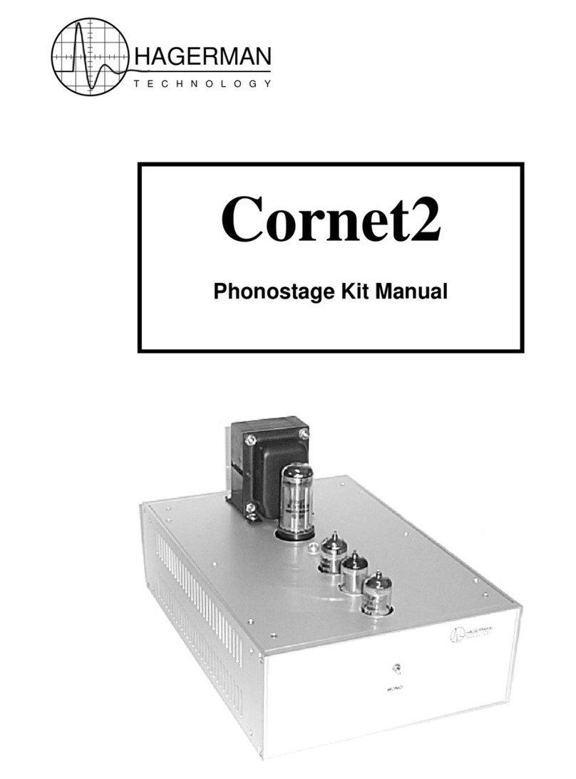
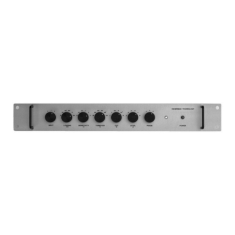
Hagerman Technology Clarinet User manual

HAGERMAN
T E C H N O L O G Y
Clarinet
Linestage Kit Manual

Clarinet Linestage Kit Manual
2
Warnings
This product uses dangerous and potentially lethal voltages. Extreme care must be taken
while assembling this amplifier and should only be attempted by a skilled technician.
The instructions in this manual are a suggested guide only and no liability is assumed by
Hagerman Technology LLC.
Copyrights & Trademarks
©Copyright Hagerman Technology LLC 2004. All rights reserved. No part of this
document may be photocopied, reproduced, or translated to another language without the
prior written consent of Hagerman Technology LLC.
Disclaimer
The information contained in this document is subject to change without notice.
Hagerman Technology LLC shall not be liable for errors contained herein or for
consequential damages in connection with the furnishing, performance, or use of this
material. See Chapter 6 for warranty information.

Clarinet Linestage Kit Manual
3
1 Before You Begin
Description
Congratulations! You have just purchased one of the highest performance-per-dollar
audiophile products available. The Clarinet linestage is intended to bring high-end audio
and construction quality into the hands of do-it-yourselfers. It is part of a line of vacuum
tube products based on a common chassis and circuit board architecture. The design is
optimized for both ease of assembly and sonic excellence.
Circuit topology is the classic SRPP (sometimes referred to as a mu-follower), which
combines the desirable features of constant current plate loading and low output
impedance. This circuit uses no feedback and runs in a class-A single-ended mode.
Vacuum tube rectification provides a gentle turn-on without the need for muting circuits.
A dc heater supply insures quiet, hum-free operation.
The Clarinet half-kit consists of these instructions, a blank circuit board, and a 1:1 drill
guide. You must purchase the remaining components from a few other sources.
Electronics are available from DigiKey and Antique Electronic Supply; the chassis from
Lansing Instruments. You may also substitute parts from your own stock.
Features
• All vacuum-tube signal path
• Pure class-A amplifier stages
• No feedback
• SRPP circuit for linearity and low output impedance
• Vacuum tube B+ rectification
Tools
This is a kit product and construction should only be attempted by skilled electronic
technicians. Chassis metalworking is also required. You will need an array of shop tools
and a good soldering iron. If you are at all unsure of this, send it back!

Clarinet Linestage Kit Manual
4
2 Parts to Buy
Kit
If you purchased a factory assembled Clarinet, skip to Chapter 5. The kit does not need
to be built as specified, part substitutions or upgrades can be made at your discretion. It
is recommended you read this entire manual before starting.
Modifications
Here are a few simple modifications and upgrades possible to customize your unit.
Upgrade signal capacitors to “auricap” brand: Change C302 to AES #CAUD1-450.
Change C301 and C303 to AES #CAU1-450.
Upgrade to gold plated RCA jacks: Buy RCJ-45 and RCJ-36 from
www.allelectronics.com. Even better, use AES #S-H267W (white) and #S-H267R
(red).
Customize knob color: Change knobs to AES #P-K300R (red) or P-K300W (white)
or P-K300BU (blue) or P-K300Y (yellow) or P-K300C (cream).
Change chassis anodize color from clear to black: Use Lansing #B2H12-V01B.
Parts List
Parts should be ordered directly from www.digikey.com and www.tubesandmore.com
(AES), and www.lansing-enclosures.com. See lists on following pages.

Clarinet Linestage Kit Manual
5
Component Qty DigiKey References
47uF 450V 3 493-1461-ND C103, C300
10,000uF 10V 3 493-1275-ND C106, C304, C305
0.1uF 50V 2 EF1104-ND C102, C306
1uF 400V 4 PF4105-ND C301, C303
0.1uF 400V 2 PF4104-ND C302
0.01uF 2kV 2 490.4217 C100, C101
LED R/G 1 754-1235 D100
1N5821 4 1N5821DICT-ND D101, D102, D103, D104
Grommet 10* RP456-ND
Power Cord 1 Q120-ND
Heat Sink 6 HS372
Feet 4 SJ5523-0-ND
Standoff #4x1” 10* 4806K-ND
Fuse 2 F2419 F100
Dome, LED 1 L30032-ND
Grounding Post 1 J587-ND
RCA-4 1 CP-1438 J304-5
RCA-6 1 CP-1441 J300-2
AC Input 1 CCM1647-ND
Fuse Holder 1 WK0011-ND
Terminal 30 1285K-ND
Crimp 30 A27804-ND
Switch, Select 1 GH7106 S300
2N3906 2 2N3906FS-ND Q100, Q101
Pot, Volume 1 P2T3503 R301
Pot, Balance 1 P2R1503 R300
220 1W 15 220W-1-ND R101, R102, R103, R303, R306,
R307, R309, R311
680 1W 5 680W-1-ND R104, R308, R310
6.8k 1W 5 6.8KW-1-ND R100, R106, R108,
10k 1W 5 10KW-1-ND R105, R304, R314
330k 1W 5 330KW-1-ND R107, R302, R312
3.0 5W 1 3.0W-5-ND R313
* Minimum purchased quantity.

Clarinet Linestage Kit Manual
6
Component Qty AES References
Knob 3 P-K300
Socket, 8-pin 1 P-ST8-193G
Socket, 9-pin 2 P-ST9-214G
Transformer 1 P-T370BX T100
12AU7 2 12AU7 V300, V301
5Y3GT 1 5Y3GT V100
Screw #10 1* P-H245
Nut #10 1* S-HHN1032
Washer #10 1* S-HLW10
Screw #4 3* S-HS440-14
Nut #4 2* S-HHN440
Lug 1* S-H112
Component Qty Lansing References
Chassis 1 B2H12-V01A

Clarinet Linestage Kit Manual
7
3 Assembly
Chassis
The instructions below refer specifically to the Lansing Instruments’ enclosure.
Nevertheless, you can still use a low-cost classic “Hammond” style chassis. Follow these
step-by-step instructions to machine the chassis pieces. If you plan to use upgraded RCA
jacks or other controls, some mounting holes will not be the same as those specified on
the drill guides; they need to be lowered to prevent interference with the circuit board.
Use a scissor to notch out the four alignment holes in the printed drill guide.
Place the drill guide on top of a blank top cover; align so the mounting holes are
centered in the crosshairs. Use a metal punch (sharp nail) to mark the center of
each hole.
Drill guide placed on top cover.
Cut out the front and rear panel drill guides using a straight edge and razor blade.

Clarinet Linestage Kit Manual
8
Guide cut to fit rear panel.
Carefully drill holes on top cover, front and rear panels. Large holes are best
done using punches, but a step-drill also works fine. A file may be needed to get
a clean rectangular cutout on the rear panel.
Wash the top cover with dishsoap to remove fingerprints and grime.
Finished chassis pieces.
Circuit Board
Assemble in the following order, solder and clip leads before continuing.
Solder sockets onto the backside of circuit board. Insure rotation of octal socket
is correct (see dimple).
Add six standoffs to bottom of circuit board using #4 nuts.
Add two grommets.

Clarinet Linestage Kit Manual
9
Install quick release terminals (for transformer wiring).
Install all resistors.
Install diodes and transistors.
Install all capacitors.
Install fuse holder.
Install RCA jacks.
Clip the front metal feet off the volume & balance potentiometers. This is to
prevent a short to a circuit trace below them. Install both.
Install select switch. Set rotation so flat on shaft points to 7:30 o’clock. Insert
miniature limit pins to locations at 12:00 and 3:00 o’clock. Add retaining sticker.
Install heat sink shields near RCA connectors and transformer wiring.
Install LED onto backside of circuit board. Keep leads as long as possible (about
one inch). Tab on side labeled “LED*”.
Soak and brush assembly in 99% isopropyl alcohol to remove solder flux residue.
Blow dry.
Completed circuit board.
Integration
If built properly, everything should fit together like a glove.
Install rubber grommets to top cover.
Install LED window to top cover.

Clarinet Linestage Kit Manual
10
Mount transformer to top cover using the #10 hardware with primary wires
towards outside.
Mount circuit board assembly to top cover, routing transformer wires through
grommets.
Cut length of transformer wires to 5 inches above circuit board. Save the scraps!
Add crimp terminals to all of the transformer wires.
Plug in the transformer wires to the terminals on the circuit board. Use the
silkscreened chart for proper voltage selection.
Add crimp terminals to both ends of scrap wires colored brown, blue, and
brown/yellow.
Add crimp terminals to one end of scrap wires colored green and green/yellow.
Solder both open ends of the green and green/yellow wires to the eyelet lug.
Install the ground jack to rear panel with above eyelet lug secured under the nut.
Install ac input connector.
Connect the brown/yellow wire from the L terminal to a switch terminal. Connect
the brown wire to the other switch terminal. Connect the blue wire to the N
terminal, and the green/yellow wire to the E terminal.
Rear panel showing wiring.
Connect L (brown), N (blue), and E (green) wires from rear panel to terminals on
circuit board.
Secure rear panel to assembly using #4 screws on the RCA jacks.
Install front panel. Secure in place with switch and potentiometer nuts.
Add chassis side panels.
Add fuse.
Turn select switch to center position. Apply knob pointing straight up.
Set volume and balance controls with detent flat at center position. Add knobs
pointing straight up.
Install vacuum tubes
Add feet to bottom cover. Do not install until after testing.

Clarinet Linestage Kit Manual
11
Completed assembly.

Clarinet Linestage Kit Manual
12
4 Testing & Installation
Testing
Double-check all of your work before applying power. Wear safety glasses, turn on the
power and check for smoke. The LED should be red, and then switch to green after
about 20 seconds. This indicates both heater and high voltage circuits are working.
Measure power supply and plate voltages using a DVM. Voltages are marked on
circuit board and schematic. Due to tube variations, these voltages will range as
much as +/-10V.
Connect a 1kHz sinewave signal and observe output on oscilloscope. Insure all
controls are functional.
Turn off, remove power cord and install bottom cover.
Square wave performance at 10kHz and 1kHz residual distortion.
Connections
The Clarinet connects to your audio system just like any other linestage. Top RCA jacks
are left channel, bottom are right. Please note, the Clarinet inverts signal polarity. You
can compensate for this by swapping speaker terminals.
Listen. Roll tubes. Enjoy.

Clarinet Linestage Kit Manual
13
5 Specifications
The following specifications are subject to change without notice.
Item Specification
Gain 15dB
Input Impedance 100k ohm
Output Impedance 3k ohm
Bandwidth 10Hz to 100kHz
Balance Control +/-3dB
Distortion 0.08% @1kHz @1Vrms
SNR 83dB A-weighted
Phase Inverted
Size (PCB) 7.25 x 11.65 inches
Size (Chassis) 8 x 12 x 3 inches
Input Power 25W
Input Voltage 100V, 110V, 120V, 200V, 220V, 240V
Tube Compliment 12AU7 (ECC82) x 2, 5Y3GT x 1

Clarinet Linestage Kit Manual
14
6 Warranty & Service
Warranty
Hagerman Technology LLC warrants this product free of defects in materials and
workmanship for 10 years (90 days for tubes). If you discover a defect, Hagerman
Technology LLC will, at its option, repair or replace the product at no charge to you
provided you return it during the warranty period, transportation charges prepaid to
Hagerman Technology LLC. This warranty does not apply if the product has been
damaged by negligence, accident, abuse or misuse or misapplication, has been damaged
because it has been improperly connected to other equipment or has been modified
without the express written permission of Hagerman Technology LLC. This warranty is
limited to the replacement or repair of this product and not to damage to equipment of
other manufacturers.
Any applicable implied warranties, including warranty of merchantability, are limited in
duration to a period of the express warranty as provided herein beginning with the
original date of purchase and no warranties, whether express or implied shall apply to the
product thereafter.
Under no circumstances shall Hagerman Technology LLC be liable for any loss, direct,
indirect, incidental, special, or consequential damage arising out of or in connection with
the use of this product.
Service
Refer to Chapter 4 for troubleshooting information. If the problem persists, contact
Hagerman Technology for service at www.hagtech.com.
Hagerman Technology LLC
PO Box 61911
Honolulu, HI 96839 USA
808-383-2704 (voice)

Clarinet Linestage Kit Manual
15

1.500in
1.500in
2.000in
3.125in
1.750in
5.000in
5.000in
1.500in
1.500in
3.500in
1.000in
Ø1.125in
(2places)
Ø1.375in
Ø0.688in
(2places)
Ø0.187in
(4places)
Ø0.125in
(#4countersink)
(10places)
Ø0.359in

0.275in2.501in2.500in
1.000in
0.270in
1.270in
0.354in
0.530in
0.530in
0.048in
0.212in
2.500in
2.500in
Ø0.375inØ0.375inØ0.375in
Ø0.250in
Ø0.438in
(10places)
Ø0.125in
(#4countersink)
(3places)


A
A
B
B
C
C
D
D
E
E
F
F
G
G
5 5
4 4
3 3
2 2
1 1
4
6
red
red
red/yel
yel
yel
yel/blk
grn
grn
grn/yel
L
E
N
vio
8
2
Blu/Yel
Brn/Yel
Blu
Brn
Blk
Blk/Red
Wht/Blk
Wht
100V 110V 120V 200V 220V 240V
NC
NC
NC
NC
NC
NC
NC
NC
NC
NC
NC
NC
NC
NC NC
NC NC
NC
NC
NC NC
NC NC
NC
SSS
SSS
LLL
LLL
LLL
NNNNNN
NNN
This document contains proprietary information and except with written permission
of Hagerman Technology LLC such information shall not be published, or disclosed to
others, or used for any purpose, and the document shall not be copied in whole or in
part. Copyright Hagerman Technology LLC 2004. All rights reserved.
blu/yel
blu
wht
wht/blk
blk/red
blk
brn
brn/yel
L
N
S
SLO-BLO
RG
n/a A
Constructor: Powersupply
Hagerman Technology LLC
P.O. Box 26437
Honolulu, HI 96825
01Thursday, April 08, 2004
Title
Size Document Number Rev
Date: Sheet of
C103
47uF
450V
C106
10mF
10V
R100
6k8
1W
C101
10nF
AC
C102
100nF
50V
D101-D104
1N5821
1
2
3
4
F100
1A
R103
220
C100
10nF
AC
T100
370BX
V100
5Y3
R101
220
R102
220
Q100
PNP Q101
PNP
R104
680
1W
R105
10k
R107
330k
1W
D100
LED
R108
6k8
R106
6k8
H+
B+

A
A
B
B
C
C
D
D
E
E
F
F
G
G
5 5
4 4
3 3
2 2
1 1
1,6
2,7
3,8
This document contains proprietary information and except with written permission
of Hagerman Technology LLC such information shall not be published, or disclosed to
others, or used for any purpose, and the document shall not be copied in whole or in
part. Copyright Hagerman Technology LLC 2004. All rights reserved.
ONE CHANNEL SHOWN
SELECT
BALANCE
VOLUME
280V
140V
145V
6mA
4.0V
4,5
9
+15dB
6.2V
n/a A
Constructor: Clarinet Linestage
Hagerman Technology LLC
P.O. Box 26437
Honolulu, HI 96825
03Thursday, April 08, 2004
Title
Size Document Number Rev
Date: Sheet of
H+
B+
R302
330k
V300A
12AU7
R303
220
R310
680
V301A
12AU7 C303
1uF
400V
R312
330k
R304
10k
1W
C300
47uF
450V
C301
1uF
400V
C302
100nF
400V
R301
50k
Log
S300
R309
220
R308
680
R306
220
R307
220
J304
Out
R311
220
R300
50k
Lin
J301
In
J300
In
J302
In
C304
10mF
10V
H300
12AU7
C305
10mF
10V
H301
12AU7
C306
100nF
50V
R313
3R0
5W
R314
10k
1W
J305
Out
Table of contents
Other Hagerman Technology Amplifier manuals

Hagerman Technology
Hagerman Technology Cymbal User manual

Hagerman Technology
Hagerman Technology Archiver User manual

Hagerman Technology
Hagerman Technology Bugle Pro User manual

Hagerman Technology
Hagerman Technology Bugle User manual

Hagerman Technology
Hagerman Technology Cornet2 User manual

Hagerman Technology
Hagerman Technology The Ripper User manual