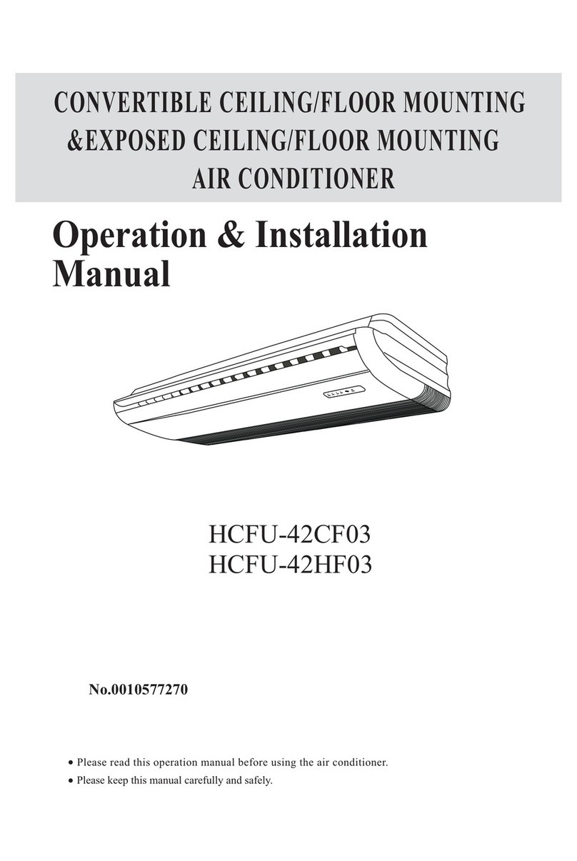
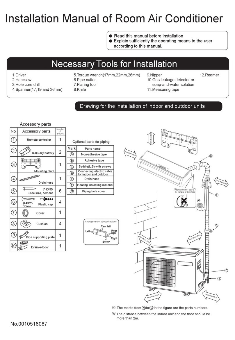
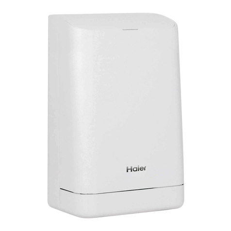
Haier AP71DFCHRA Installation and operating instructions

Please read this manual before using the air conditioner.
Keep this manual for future reference.
PACKAGED TYPE ROOM AIR CONDITION
OPERATION MANUAL AND INSTALLATION MANUAL
ER
h
s
i
l
g
n
E
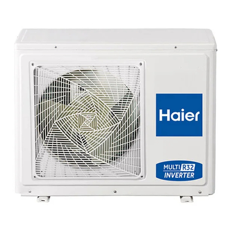
This appliance is filled with R32.
AP71DFCHRA/1U71RECFRA
AP24DFCHRA/1U24RECFRA
●
0011509384

Contents
11
12
21
PARTS AND FUNCTIONS
OPERATION............................................................................................................................
INDOOR AND OUTDOOR UNIT INSTALLATION..................................................................
MAINTENANCE 25
19
CAUTIONS.............................................................................................................................
.......................................................................................................
TROUBLE SHOOTING........................................................................................................... 20
................................................................................
WARNING:
·If the supply cord is damaged, it must be replaced by the manufacturer,its service agent or
similarly qualified persons in order to avoid a hazard.
·
·All the cables shall have got the European authentication certificate. During installation, when the
·connecting cables break off, it must be assured that the grouding wire is the last one to be broken off.
The explosion-proof breaker of the air conditioner should be all-pole switch. Distance between its two
contacts should be not less than 3mm. Such means fordisconnection must be incorporated in the
·Make sure installation is done according to local wiring regulation by professional persons.
·
·A leakage explosion-proof breaker must be installed.
Make sure ground connection is correct and reliable.
Read the precautions in this manual
carefully before operating the unit. This appliance is filled with R32.
Do not use means to accelerate the defrosting process or to clean, other than those
recommended by the manufacturer.
·
Keep this manual where the user can easily find it.
The appliance must be stored in a room without continuously operating ignition sources (for
example: open flames, an operating gas appliance or an operating electric heater).
Do not pierce or burn.
·
·Be aware that refrigerants may not contain an odour.
·The appliance must be installed, operated and stored in a room with a floor area larger than
3m.
·
·Do not use a refrigerant other than the one indicated on the outdoor unit(R32) when installing,
moving or repairing. Using other refrigerants may cause trouble or damage to the unit, and
personal injury.
wiring.
2
1
This appliance can be used by children aged 8 years and above and persons with reduced
physical, sensory or mental capabilities or lack of experience and
knowledge if they have been given superivision or instruction concering use of the
appliance in a safe way and understand the hazards involved. Children shall not play with
the appliance.
The appliance shall be installed in accordance with national wiring regulations
h
s
i
l
g
n
E
AND WIFI FUNCTION

Loading and Unloading/Transporting Management/Storage Requirements
1) The products shall be carefully handled during loading and unloading.
2) Rude and barbarous handling such as kicking, throwing, dropping, bumping, pulling and rolling is not
allowed.
3) The workers engaged in loading and unloading must be subject to necessary trainings on the potential
hazards caused by barbarous handling.
4) Dry powder extinguishers or other suitable fire extinguishing apparatus within the period of validity shall be
equipped at the loading and unloading site.
5) The untrained personnel cannot be engaged in loading and unloading of flammable refrigerants air
conditioner.
6) Before loading and unloading, anti-static measures shall be taken, and phones cannot be answered during
loading and unloading.
7) Smoking and open fire are not allowed around the air conditioner.
Transporting Management Requirements
1) The maximum transporting volume of finished products shall be determined as per local regulations.
2) The vehicles used for transporting shall be operated as per local laws and regulations.
3) Dedicated after-sales vehicles shall be used for maintenance, and exposed transporting of refrigerant
cylinders and the products to be maintained is not allowed.
4) The rain cover or similar shielding material of transporting vehicles shall be provided with certain flame
retardancy.
5) Leakage warning device of flammable refrigerant shall be installed inside the closed-type compartment.
6) Anti-static device shall be equipped inside the compartment of transporting vehicles.
7) Dry powder extinguishers or other suitable fire extinguishing apparatus within the period of validity shall be
equipped inside the driver's cab.
8) Orange-white or red-white reflective stripes shall be pasted on the sides and tail of the transporting vehicles,
to remind the vehicles behind of keeping distance.
9) The transporting vehicles shall run at a constant speed, and heavy acceleration/deceleration shall be avoided.
10) Combustibles or the static articles cannot be transported simultaneously.
11) High-temperature area shall be avoided during transporting, and necessary radiating measures shall be taken
in case the temperature inside the compartment is too high.
Storage Requirements
1) The storage package of equipment used shall be such that no leakage of refrigerant will be caused due to
mechanical damage of the equipment inside.
2) The maximum quantity of the equipment allowed to be stored together shall be determined as per local
regulations.
Installation Instructions
WARNING!
The area of the room in which R32 refrigerant air conditioner is installed cannot be less than the minimum
area specified in the table below, to avoid potential safety problems due to out-of-limit of refrigerant
concentration inside the room caused by leakage of refrigerant from refrigeration system of the indoor unit.
Once the horn mouth of connecting lines is fastened, it may not be used again (the air tightness may be
affected).
A whole connector wire shall be used for indoor/outdoor unit as required in the operation specification of
installation process and operation instructions.
Minimum Room Area
Type LFL
kg/m3
Total Mass Charged/kg
Minimum Room Area/m2
R32 0.306
1.224 1.836 2.448 3.672 4.896 6.12 7.956
3 6 13 23 36 60
2
The maximum refrigerant charge amount (M)
Unit model M kg Unit model M kg Unit model M kg Unit model M kg
1U20YEEFRA 0.62 1U25S2SM1FA 0.85 1U35MEEFRA 0.82 1U50JEFFRA-TCS 1.35
1U25BEEFRA 0.74 1U25YEMFRA 0.67 1U35S2PJ1FA 1.15 1U50MEE/MFRA 1.30
1U25BEFFRA 0.90 1U35BEEFRA 0.82 1U35S2SM1FA 1.14 1U50S2SJ2FA 1.35
1U25BEFFRA-TCS 0.90 1U35BEEFRA-TCS 0.82 1U35YEMFRA 0.70 1U68REE/F/MFRA 1.60
1U25S2PJ1FA 1.15 1U35BEFFRA 0.92 1U50JEFFRA 1.35 1U71S2SR1FA 1.60
1U42S2SM1FA 1.14 1U50S2PR1FA 1.60 1U25JEJFRA 1U35JEJFRA
1U50REJFRA 1.60
0.94 0.94
1U71REAFRA
1.60
h
s
il
g
nE
1U71RECFRA
1.60

1. Procedures: operation shall be made as per controlled procedures to minimize the probability of risks.
2. Area: area shall be divided and isolated appropriately, and operation in an enclosed space shall be avoided.
Before the refrigeration system is started or before hot working, ventilation or opening of the area shall be
guaranteed.
3. Site inspection: the refrigerant shall be checked.
4. Fire control: the fire extinguisher shall be placed nearby, and fire source or high temperature is not allowed;
the sign of “No smoking” shall be arranged.
1. Indoor unit: nitrogen is sealed during the delivery of indoor units (inside the evaporator), and the red sign at
the top of the green plastic seal cap on the evaporator air pipes of the indoor unit shall be checked first after
unpacking. In case the sign is raised, the nitrogen sealed still exists. Afterwards, the black plastic seal cap at the
joint of evaporator liquid pipes of the indoor unit shall be pressed, to check whether nitrogen still exists. In case
no nitrogen is sprayed out, the indoor unit is subject to leakage, and installation is not allowed.
2. Outdoor unit: the leak detection equipment shall be extended into the packing box of the outdoor unit, to
check whether the refrigerant is leaking. If the refrigerant leakage is identified, installation is not allowed, and the
outdoor unit shall be delivered to the maintenance department.
1. The room area checked cannot be less than the area specified on the warning sign of the indoor unit.
2. Inspection on the surrounding environment of place of installation: the outdoor unit of flammable
refrigerants air conditioner cannot be installed inside an enclosed room reserved.
3. Power supply, switches or other high-temperature articles such as the fire source and oil heater shall be
avoided below the indoor unit.
4. The power supply shall be provided with earthing wire and be reliably earthed.
5. While punching the wall with an electric drill, whether embedded water/electricity/gas pipelines are
designed at the hole preset by the user shall be verified in advance. It is recommended that the through-wall holes
reserved shall be used as much as possible.
1. Favorable ventilation shall be maintained at the place of installation (doors and windows are opened).
2. Open fire or high-temperature heat source (including welding, smoking and oven) higher than 548 is not
allowed within the scope of flammable refrigerant.
3. Anti-static measures shall be taken, such as the wearing of cotton clothes and cotton gloves.
4. The place of installation shall be convenient for installation or maintenance, and cannot be adjacent to heat
source and flammable and combustible environment.
5. In case of refrigerant leakage of the indoor unit during installation, the valve of the outdoor unit shall be
closed immediately, and windows shall be opened, and all the personnel shall be evacuated. After the leakage of
refrigerant is handled, the indoor environment shall be subject to concentration detection. Further handling is not
allowed until the safety level is reached.
6. In case the product is damaged, it must be delivered to the maintenance point. Welding of refrigerant
pipelines at the user’s site is not allowed.
7. The installation position of air conditioner shall be convenient for installation or maintenance. Barriers shall
be avoided around the air inlet/outlet of the indoor/outdoor unit, and the electrical appliance, power switches,
sockets, valuables and high-temperature products within the scope of both sidelines of the indoor unit shall be
avoided.
3
No fire source around the
place of installation
Read operator’ manual Read technical manual Operator’ manual;operating instructions
Cotton clothes Anti-static gloves BEWARE
ELECTROSTATICS Goggles
h
s
i
l
g
n
E

•Electrical Safety Requirements
Note:
1. The surrounding conditions (ambient temperature, direct sunlight and rainwater) shall be noticed during
electrical wiring,with effective protective measures being taken.
2. Copper wire cable in line with local standards shall be used asthe power line and connector wire.
3. Both the indoor unit and outdoor unit shall bereliably earthed.
4. Wiring for the outdoor unit shall be made first and then the indoor unit. The air conditioner can only be
powered on after wiring and pipe connection.
5. The dedicated branch circuit must be used, and leakage protector with sufficient capacity must be installed.
•Qualification Requirements of Installer
Relevant qualification certificate must be obtained as per national laws and regulations.
•Indoor Unit Installation
1. Fixation of wall panel and piping layout
In case of left/right water pipe connection for the indoor unit, or in case the evaporator interface of the indoor
unit and the horn mouth of the connecting piping cannot be extended to the outdoor side for installation, the
connector pipes shall be connected to the evaporator piping interface of the indoor unit in the process of horn
mouth.
2. Piping layout
During layout of connecting pipes, drain hose and connector wires, the drain hose and connecting wire shall
be placed at the bottom and top respectively. The power line cannot be twined with the connector wire. The drain
pipes (especially inside the roomand machine) must be winded with thermal insulation materials.
3. Nitrogen charging for pressure maintaining and leak detection
After the evaporator of the indoor unit is connected to the connector pipe (after welding), nitrogen more than
4.0MPa shall be charged inside the evaporator and the piping connected to evaporator with a nitrogen cylinder
(adjusted by a reducing valve). Afterwards, the valve of the nitrogen cylinder shall be closed, for leak detection
with soapy water or leak detecting solution. The pressure shall be maintained for more than 5 minutes, and then
whether the system pressure is reduced or not shall be observed. In case the pressure is reduced, leakage can be
identified. After theleak point ishandled, the steps above shall be repeated.
After the evaporator of the indoor unit is connected to connecting piping, nitrogen shall be charged for
pressure maintaining and leak detection. Afterwards, the evaporator shall be connected to the two-way stop valve
and three-way stop valve of the outdoor unit. After the copper cap of the connecting piping is fastened, nitrogen
more than 4.0MPa shall be charged at the access hole of the three-way stop valve with a charging hose. The valve
of the nitrogen cylinder shall be closed, for leak detection with soapy water or leak detecting solution. The
pressure shallbe maintained for more than 5 minutes, and then whether the system pressure is reduced or not shall
be observed. In case the pressure is reduced, leakage can be identified. After the leak point is handled, the steps
above shall be repeated.
The operation above can also be completed after the indoor unit is connected to the connecting pipelines and
the two-way stop valve and three-way stop valve of the outdoor unit, after the access hole of the outdoor unit is
connected to the nitrogen cylinder and pressure gauge and after more than 4.0MPa nitrogen is charged. No leak
points are identified in the leak detection at the joint/welding junction of the indoor unit and at the joint of
connecting pipelines of the two-way stop valve and three-way stop valve of the outdoor unit. It must be
guaranteed that each joint isavailable for leak detection during installation.
The next step (vacuumizing with a vacuum pump) can only be continued after the installation steps (nitrogen
charging for pressure maintaining and leak detection normal) are completed.
•Outdoor Unit Installation
1. Fixation and connection
Note:
a) Fire source shall be avoided within 3m around theplaceof installation.
b) The leak detection equipment of refrigerant shall be placed at a low position in the
outdoor, and shall be opened.
4
h
s
i
l
gn
E

1) Fixation
The support of the outdoor unit shall be fixed onto the wall surface, and then the outdoor unit shall be fixed onto
the support horizontally. In case the outdoor unit is wall-mounted or roof-mounted, the support shall be firmly
fixed, to avoid the damage of strong wind.
2) Installation of connecting pipes
The cone of the connecting pipes shall be aligned with the conical surface of corresponding valve connector.
The nut of connecting pipes shall be installed at a proper position and then be tightened with a spanner. Excessive
tightening torqueshall be avoided, or otherwise the nut may be damaged.
•Vacuumizing
A digital vacuum gauge shall be connected for vacuumizing. The duration of vacuumizing shall be at least 15
minutes, and the pressure of the vacuum gauge shall be below 60Pa.Afterwards, the vacuumizing equipment shall
be closed, and whether the reading of the digital vacuum gauge is increased or not shall be observed after the
pressure is maintained for 5 minutes. In case no leakage is identified, the two-way stop valve and three-way stop
valve of the outdoor unit may be opened. Finally, the vacuumizing hose connected to the outdoor unit can be
disassembled.
•Leak Detection
The joint of connecting pipes for the outdoor unit shall be subject to leak detection with soap bubble or
dedicated leak detection equipment.
•Post-installation Inspection Items and Test Run
Post-installation Inspection Items
qesnoCdekcehCeBotsmetI uence of Improper Installation
Whether the installation is firmor not The unit may fall, vibrateor make a noise
Whether the inspection on air leakage is completed The refrigerating capacity (heating capacity) may be
insufficient
Whether the unit is fully insulated Condensation or drip may occur
Whether the drainage is smooth or not Condensation or drip may occur
Whether the power voltage is identical to that
marked on the nameplate
Failure may occur or the parts may be burned
Whether the circuit and pipeline are installed
correctly
Failure may occur or the parts may be burned
Whether the unit is safely earthed Electric leakage may occur
Whether the type of wire is in line with relevant
regulations
Failure may occur or the parts may be burned
Whether barriers are identified at the air inlet/outlet
of the indoor/outdoor unit
The refrigerating capacity (heating capacity) may be
insufficient
Whether the length of refrigerant pipes and the
refrigerant amount charged are recorded
The refrigerant amount charged cannot be confirmed
Test Run
1. Preparations
(1) Power on is not allowed before all the installation operations are completed and before the leak
detection is proven qualified.
(2) The control circuit shall be connected correctly and all the wires shall be firmly connected.
(3) The two-way stop valve and three-way stop valve shall be opened.
(4) All the scattered articles (especially the metal filing and thread residue) shall be removed from the unit
body.
2. Methods
(1) Switch on the power supply and press the “ON/OFF” on the remote controller, after which the air
conditioner will start operating.
(2) Press “Mode” to select refrigeration, heating and sweeping wind, and observe whether the air
conditioner is under normal operation.
5
h
s
i
l
g
n
E

Relocation Procedures
Note: in case relocation is required, the joint of evaporator gas/liquid pipes of the indoor unit shall be cut off with
a cutting knife. Connection is only allowed after re-flaring (the same to the outdoor unit).
Maintenance Instructions
Maintenance Precautions
Precautions
•For all the faults requiring welding the refrigeration pipelines or components inside the refrigeration system
of R32 refrigerant air conditioners, maintenance at the user’s site is never allowed.
•For the faults requiring radical disassembly and bending operation of the heat exchanger, such as the
replacement of the outdoor unit chassis and integral disassembly of the condenser, inspection and maintenance at
the user’s site are never allowed.
•For the faults requiring replacement of the compressor or parts & components of refrigeration system,
maintenance at the user’s site is not allowed.
•For other faults not involved in the refrigerant container, internal refrigeration pipelines and refrigeration
elements, the maintenance at the user’s site is allowed, including the cleaning and dredging of the refrigeration
systemrequiring no disassembly of refrigeration elements and no welding.
•In case replacement of gas/liquid pipes is required during maintenance, the joint of evaporator gas/liquid
pipes of the indoor unit shall be cut off with a cutting knife. Connection is only allowed after re-flaring (the same
to the outdoorunit).
Qualification Requirements of Maintenance Personnel
1. All the operators or the maintenance personnel involved in refrigerating circuits shall be provided with the
effective certificate issued by an industry-accepted assessment institute, to ensure that they are qualified for safety
disposal of refrigerant asrequired in the assessment regulations.
2. The equipment can only be maintained and repaired as per the method recommended by the manufacturer.
In case the assistance from personnel of other disciplines is required, the assistance shall be supervised by the
personnel with qualification certificate involved in flammable refrigerant.
6
h
s
il
g
nE

Inspection on Maintenance Environment
•Before operation, the refrigerant leaked in the room is not allowed.
•The area of the roomin which maintenance is made shall bein linewith the nameplate.
•Continuous ventilation shall be maintained during maintenance.
•Open fire or high-temperature heat source higher than 548 degree which can easily give birth to open fire is
not allowed inside the room within the maintenance area.
•During maintenance, the phones and the radioactive electronics of all the operators inside the room must be
powered off.
•One dry powder or carbon dioxide extinguisher shall be equipped inside the maintenance area, and the
extinguisher must be under available state.
Maintenance Site Requirements
•The maintenance site shall be provided with favorable ventilation and must be flat. Arrangement of the
maintenance site inside the basement is not allowed.
•Welding zone and non-welding zone shall be divided at the maintenance site, and shall be clearly marked. A
certain safety distance must be guaranteed between the two zones.
•Ventilators shall be installed at the maintenance site, and exhaust fans, fans, ceiling fans, floor fans and
dedicated exhaust duct can be arranged, to meet the requirements of ventilation volume and uniform exhaust, and
to avoid accumulation of refrigerant gas.
•Leak detection equipment for flammable refrigerant shall be equipped, with relevant management system
being established. Whether the leak detection equipment is under available state shall be confirmed before
maintenance.
•Sufficient dedicated vacuum pumps of flammable refrigerant and refrigerant charging equipment shall be
equipped, with relevant management system for maintenance equipment being established. It shall be guaranteed
that the maintenance equipment can only be used for vacuumizing and charging of one type of flammable
refrigerant, and mixed usage is not allowed.
•The master power switch shall be arranged outside the maintenance site, with protective (anti-explosive)
devicebeing equipped.
•Nitrogen cylinders, acetylene cylinders and oxygen cylinders shall be placed separately. The distance
between the gas cylinders above and the working area involved in open fire shall be at least 6m. The anti-backfire
valve shall be installed for the acetylene cylinders. The color of the acetylene cylinders and oxygen cylinders
installed shall meet the international requirements.
•The warning sign of “No Fire” shall be arranged inside the maintenance area.
•Fire control device suitable for electric appliance such as the dry powder extinguisher or carbon dioxide
extinguisher shall be equipped, and shall always be under the availablestate.
•The ventilator and other electrical equipment at the maintenance site shall be relatively fixed, with
standardized pipe routing. Temporary wires and socketsat the maintenance site are not allowed.
Leak Detection Methods
•The environment in which the refrigerant leakage is checked shall be free from potential ignition source.
Leak detection with halogen probes (or any other detector with open fire) shall be avoided.
•For the system containing flammable refrigerant, leak detection may be realized with electronic leak
detection equipment. During leak detection, the environment in which the leak detection equipment is calibrated
shall be free from refrigerant. It shall be guaranteed that the leak detection equipment will not become potential
ignition source, and is applicable to the refrigerant to be detected. Leak detection equipment shall be set at a
percentage of the LFL of the refrigerant and shall be calibrated to the refrigerant employed, and the appropriate
percentage of gas (25 % maximum) is confirmed.
•The fluid used for leak detection shall be applicable to most of the refrigerant. The use of chlorine-
containing solvent shall be avoided, to avoid chemical reaction between chlorine and refrigerant and corrosion to
copper pipelines.
•In case leakage is suspected, the open fire at the site shall be evacuated or be put out.
•In case welding is required at the leakage position, all the refrigerants shall be recovered, or be isolated at a
position far from the leak point with a stop valve. Before and during welding, the whole system shall be purified
with OFN.
7
h
s
i
l
g
n
E

Safety Principles
•During product maintenance, favorable ventilation shall be guaranteed at the maintenance site, and the close
of all the doors/windows is not allowed.
•Operation with open fire is not allowed, including welding and smoking. The use of phones is also not
allowed. The user shall be informed that cooking with open fire is not allowed.
•During maintenance in a dry season, when the relative humidity is less than 40%, anti-static measures shall
be taken,including the wearing of cotton clothesand cotton gloves.
•In case the leakage of flammable refrigerant is identified during maintenance, forced ventilation measures
shallbe taken immediately, and the sourceof leak shall be plugged.
•In case the product damaged must be maintained by disassembling the refrigeration system, the product
must be delivered to the maintenance point. Welding of refrigerant pipelines at the user’s site is not allowed.
•During maintenance, in case re-treatment is required due to lack of fittings, the air conditioner shall be reset.
•The refrigeration system must be safely earthed in the whole course of maintenance.
•For the door-to-door service with refrigerant cylinders, the refrigerant charged inside the cylinder cannot
exceed the specified value. The cylinder placed in vehicles or at the installation/maintenance site shall be fixed
perpendicularly and be kept away from heat sources, ignition source, source of radiation and electric appliance.
Maintenance Items
Maintenance Requirements
•Before the refrigeration system is operated, the circulating systemshall be cleaned with nitrogen. Afterwards,
the outdoor unit shall be vacuumized, the duration of which cannot be less than 30 minutes. Finally, 1.5~2.0MPa
OFN shall be used for nitrogen flushing (30 seconds~1 minute), to confirm the position requiring treatment.
Maintenance of the refrigeration system is only allowed after the residual gas of flammable refrigerant is removed.
•During the use of refrigerant charging tools, cross contamination of different refrigerants shall be avoided.
The total length (including the refrigerant pipelines) shall be shortened as much as possible, to reduce the residual
of refrigerant inside.
•The cylinders of refrigerant shall be kept upright, and be fixed.
•Before refrigerant charging, the refrigeration system shall be earthed.
•The refrigerant charged shall be of the type and volume specified on the nameplate. Excessive charging is
notallowed.
•After maintenance of the refrigeration system, the system shall be sealed with a safe manner.
•The maintenance in progress shall not damage or lower the original class of safety protection of the system.
Maintenance of Electrical Components
•Partial of the electrical component under maintenance shall be subject to inspection on refrigerant leakage
with dedicated leak detection equipment.
•After the maintenance, the components with safety protection functions cannot be disassembled or removed.
•During the maintenance of sealing elements, before opening the seal cover, the air conditioner shall be
powered off first. When power supply is required, continuous leak detection shall be carried out at the most
dangerous position,toavoid potential risks.
•During maintenance of electrical components, the replacement of enclosures shall not affect the level of
protection.
•After maintenance, it shall be guaranteed that the sealing functions will not be damaged or the sealing
materials will not lose the function of preventing the entry of flammable gas due to aging. The substitute
componentsshall meet the recommended requirements of the air conditioner manufacturer.
Maintenance of Intrinsically Safe Elements
The intrinsically safe element refers to the components working continuously inside flammable gas without any
risks.
•Before any maintenance, leak detection and inspection on earthing reliability of the air conditioner must be
carried out, to ensure no leakage and reliable earthing.
•In case the allowable voltage and current limit may be surpassed during the service of the air conditioner,
any inductance or capacitance cannot be added in the circuit.
•Only the elements appointed by the air conditioner manufacturer can be used as the parts and components
replaced, or otherwise a fire may be triggered in case of refrigerant leakage.
•For the maintenance not involved in system pipelines, the system pipelines shall be well protected, to ensure
that no leakage willbecaused dueto maintenance.
•After maintenance and before test run, the air conditioner must be subject to leak detection and inspection on
earthing reliability with leak detection equipment or leak detecting solution. It shall be guaranteed that the startup
inspection is carried out without leakage and under reliable earthing.
8
h
s
il
g
nE

Removal and Vacuumizing
The maintenance or other operations of the refrigeration circuit shall be made as per conventional procedures.
Moreover, the flammability of refrigerant shall also be mainly considered. The following procedures shall be
followed:
•Refrigerant clearing;
•Pipeline purification with inert gas;
•Vacuumizing;
•Pipeline purification again with inert gas;
•Pipeline cutting or welding. The refrigerant shall be recovered to a proper cylinder. The system shall be
purged with OFN, to ensure safety. The step above may need to be repeated for several times. Compressed air or
oxygen cannot beused for purging.
In the course of purging, OFN shall be charged inside the refrigeration system under vacuum state, to reach
the operating pressure. Afterwards, the OFN shall be discharged to the atmosphere. Finally, the system shall be
vacuumized. The step above shall be repeated until all the refrigerants in the system are cleared. The OFN charged
for the last time shall be discharged to the atmosphere. Afterwards, the system can be welded. The operation
above is necessary in case of pipeline welding.
It shall be guaranteed that no alight fire source is around the outlet of the vacuum pump and the ventilation is
favorable.
Welding
•Favorable ventilation must be guaranteed in the maintenance area. After the maintenance machine is subject
to the vacuumizing above, the system refrigerant can be discharged on the outdoor unit side.
•Before the outdoor unit is welded, it must be guaranteed that no refrigerant is inside the outdoor unit and the
systemrefrigerant has been discharged and cleared.
•The refrigeration pipelines cannot be cut with a welding gun under any circumstance. The refrigeration
pipelines must be disassembled with a pipe cutter, and the disassembly must be carried out around a ventilation
opening.
Refrigerant Charging Procedures
The following requirements are added as the supplementation of conventional procedures:
•During the use of refrigerant charging tools, cross contamination of different refrigerants shall be avoided.
The total length (including the refrigerant pipelines) shall be shortened as much as possible, to reduce the residual
of refrigerant inside;
•The cylinders of refrigerant shall be kept upright;
•Before refrigerant charging, the refrigeration system shall be earthed;
•A label must be pasted on the refrigeration system after refrigerant charging;
•Excessive charging is not allowed; the refrigerant shall be charged slowly;
•In case system leakage is identified, refrigerant charging is not allowed unless the leak point is plugged;
•During refrigerant charging, the charging amount shall be measured with an electronic scale or a spring
scale. The connecting hose between the refrigerant cylinder and the charging equipment shall be relaxed
appropriately, to avoid impact on the measuring accuracydue to stress.
Requirements on storage site of refrigerant
•The cylinder of refrigerant shall be placed in a -10~50°C environment with favorable ventilation, and
warning labels shall be pasted;
•The maintenance tool in contact with the refrigerant shall be stored and used separately, and the
maintenance tool of different refrigerants cannot be mixed.
Scrapping and Recovery
Scrapping
Before scrapping, the technician shall be completely familiar with the equipment and all its features. The safe
recovery of refrigerant is recommended. In case the refrigerant recovered needs to be reused, before which the
sample of refrigerant and oil shall be analyzed. The power supply required shall be guaranteed before tests.
(1) The equipment and operation shall be wellknown;
(2) Power supply shall be switched off;
(3) The followings shall be guaranteed before scrapping:
•The mechanical equipment shall be convenient for operation on the cylinder of refrigerant (if necessary);
•All personal protective equipment is available and being used correctly;
•The whole course of recovery shall be guided by qualified personnel;
•The recovery equipment and cylinders shall be in line with corresponding standards.
(4) The refrigeration system shall be vacuumized if possible;
9
h
s
i
l
g
n
E

(5) In case the vacuum state cannot be reached, vacuumizing shall be carried out from numerous positions, to
pump the refrigerant ineachpart of the systemout;
(6) It shall be guaranteed that the capacity of cylinders is sufficient before recovery;
(7) The recovery equipment shall be started and operated as per the operation instructions of the manufacturer;
(8) The cylinder cannot be charged too full. (The refrigerant charged cannot exceed 80% of the capacity of
cylinders)
(9) The maximum operating pressure of cylinders cannot be surpassed even only lasting for a short term;
(10) After refrigerant charging is completed, the cylinder and equipment must be evacuated rapidly, and all the
stop valves on theequipment must beclosed;
(11) Before purification and tests, the refrigerant recovered cannot be charged into another refrigeration system.
Note:
The air conditioner shall be marked (with dates and signature) after being scrapped and the refrigerant is
discharged. It shall be guaranteed that the sign on the air conditioner can reflect the flammable refrigerant
charged inside.
Recovery
During maintenance or scrapping, the refrigerant inside the refrigeration system needs to be cleared. It is
recommended that the refrigerant be cleared thoroughly.
The refrigerant can only be charged into a dedicated cylinder, the capacity of which shall match with the
refrigerant amount charged in the whole refrigeration system. All cylinders to be used are designated for the
recovered refrigerant and labeled for that refrigerant (Dedicated Cylinder for Refrigerant Recovery). The cylinders
shall be equipped with pressure relief valves and stop valves under favorable state. The empty cylinder shall be
vacuumized before usageand be kept under normal temperature if possible.
The recovery equipment shall always be under favorable working state, and be equipped with operation
instructions, to facilitate information search. The recovery equipment shall be applicable to the recovery of
flammable refrigerant. Moreover, weighing apparatus under available state with measurement certificates shall be
equipped. In addition, removable attachment joints free from leakage shall be used as the hose, and shall always
be under favorable state. Whether the recovery equipment is under favorable state and is properly maintained and
whether all the electrical components are sealed shall be checked before usage, to avoid fire in case of refrigerant
leakage. If you have any question, please consult the manufacturer.
The refrigerant recovered shall be delivered back to the manufacturer in appropriate cylinders, with
transporting instructions being attached. Mixing of refrigerant in recovery equipment (especially the cylinders) is
notallowed.
During transporting, the space in which the flammable refrigerant air conditioners are loaded cannot be
sealed. Anti-static measures shall be taken for the transporting vehicles if necessary. Meanwhile, during the
transporting, loading and unloading of air conditioners, necessary protective measures shall be taken, to protect
the air conditioner from being damaged.
During removal of the compressor or clearing of the compressor oil, it shall be guaranteed that the
compressor is vacuumized to a proper level, to ensure no residual flammable refrigerant is left inside the
lubricating oil. The vacuumizing shall be completed before the compressor is delivered back to the manufacturer.
The vacuumizing can only be accelerated by heating the compressor housing through electrical heating. Safety
shall be guaranteed when the oil is discharged from the system.
10
h
s
il
g
nE

Parts and Functions
Remote controller
Outer side of the controller
1. SELF CLEAN button
2. DRY button
3. COOL button
Used to set COOL operation.
4.
5.
n6. status
8. CLOCK display
7. Operation mode display
9. TEMP display
10.Humidity display
11. FAN SPEED display
12. SWING display
Swing up/down display
swing left/right display
14. TURBO button
15. QUIET button
16. HEAT button
17. FAN button
Used to set DRY operation.
13. TIMER ON display
TIMER OFF display
CLOCK display
TEMP button
used to change setting
temperature
ON / OFF button
Indoor Unit
11
NOTICE:
Humidity display is unavailable on this model.
TIMER
1
2
3
4
5
6
7
89
10
11
12
13
15
16
17
14
TURBO
SELF CLEAN
h
s
i
l
g
n
E
Display of each functio
AIR FILTER (INSIDE)

Operation
Clock set
The distance between the signal transmission head and
the receiver hole should be within 7m without any obstacle
change-over wireless telephone is installed in the type
in receiving the signals, so the distance to the indoor unit
should be shorter.
Full display or unclear display during operation indicates the
batteries have been used up. Please change batteries.
If the remote controller can’t run normally during operation,
please remove the batteries and reload several minutes later
.
Hint:
1. Use the new battery with the same two models.
2. When the remote control is abnormal during use,
please remove the battery and put the battery iback
after a few minutes.
3. If the remote control appears dimmed (sometimes
abnormal state), it means that the power has run out,
please replace the battery.
4. Please dispose of waste batteries properly.
5. Remove the batteries in case unit won’t be in usage
for a long period.
20. SMART button
18. buttonTIMER
19. buttonCLOCK
Press CLOCK button,
Press “+” or “-” to set
correct time.
Each press will increase or
decrease 1min. If the button is
kept pressed, time will change
quickly.
press APPLY, “
1
2
3
Press “HEALTH”+“HEALTH AIRFLOW” simultaneously can
set and cancel the “LOCK” function ( )
Used to set SMART
operation.
Loading of the battery
Remove the battery cover;
Load the batteries as illustrated. 2 R-03 batteries,
resetting key (cylinder); Be sure that the loading is
in line with the “+”/“-”;
Load the battery, then put on the cover again.
3
12
NOTICE:
1. The signal transmitting head is aligned with the
signal receiving window on the indoor machine.
2. The transmitting head and the receiving window
are within seven meters and there should be no
obstructions in the middle.
3. Do not throw and drop the remote control.
4.
When the room has an electronic start-up fluorescent
lamp or a converted fluorescent lamp or a
wireless telephone, the signal will be disturbed,
and the distance between the remote control and
the indoor unit will be kept close to the use.
English
23. SWING up/down button
24. SWING left/right button
26. HEALTH AIRFLOW button
21. HEALTH button
(Press the HEALTH button in the
shutdown state to enter Fan mode)
28. CODE button
A-b yard(Only A yard is available)
29. APPLY button
30. 10°C button
25. SLEEP button
22. BNT button
(BNT function is not available)
27. LIGHT button
Control the lightening and
extinguishing of the indoor
LED display board.
special heating set
function: 10 degree
heating maintaining
This function is unavailable on this model)
19
20
21
22
23 24
25
26
27
28
29
30
18
BNT
SMART
BNT
SMART

COOL,HEAT and DRY Operation
Operation
COOL,HEAT and DRY Operation
Operation
1. In DRY mode, when room temperature becomes
lower than temp. setting +2 ºC, unit will run
intermittently at LOW speed regardless of FAN
setting.
2. Remote controller can memorize each operation
status. When starting it next time, just press ON/
OFF button and unit will run in previous status.
QUIET Operation
You can use this function when silence is needed for rest or
reading.
For each press, is displayed, Air conditioner starts
QUIET function operation. In QUIET operation mode, fan
speed automatically takes low speed of AUTO fan mode.
Press QUIET button again, disappears, the operation
stops.
Unit start.
Select operation mode.
Press the COOL button on
the remote controller.
Press the HEAT button on the remote controller.
Press the DRY button on the remote controller.
1
2
TURBO/QUIET Operation
TURBO TURBO Operation
QUIET Operation:
TURBO Operation:
Note
During TURBO operation, in rapid COOL mode , the room
will show inhomogeneous temperature distribution.
When you need rapid cooling, you can use this function.
Press TURBO button, the remote controller will show ,
and then achieve to the turbo function. Press again this
TURBO button , the turbo function will be cancelled.
13
Hint:
TURBO
SELF CLEAN
TURBO
SELF CLEAN
h
s
i
l
g
n
E

Operation
Before going to bed, you can simply press the SLEEP
button and unit will operate in SLEEP mode and bring you
a sound sleep.
Press SLEEP
button.
Operation Mode
Comfortable SLEEP
1.When the sleeping signal is received, the air conditioner
runs according to the system's preset sleep temperature
curve.
2.After setting the SLEEP mode, if the setting temperature
is adjusted manually, the temperature will be operated
according to the manual setting.
3.In SMART mode
4. In FAN mode
It has no SLEEP function.
The unit operates in corresponding sleep mode
adapted to the automatically selected operation mode
5. Set the SLEEP mode, the air conditioner will
automatically shut down after 8 hours.
14
English
Unit will start running to reach the
temp. setting on LCD.
AN Operation
changes as follows:
Unit will run at selected fan speed.
button.
pressed, temp. setting
increases 1ºC.
pressed, temp. setting
decreases 1ºC.
1
2
Hint:
You can control the unit temp. by the
panel "<"">" independently . Every
time the button is pressed, temp.
setting increases/ decreases 0.5ºC.
The range of setting temperature is
16℃-30℃.
TURBO
SELF CLEAN BNT
SMART

Hint:
the outlet grills of the air conditioner are opened, and
the unit goes on working under the condition before the
grille will close automatically.
Cannot pull direct the outlet grille by hand. Otherwise, the
grille will run incorrectly. If the grille is not run correctly,
stop for a minute and then start, adjusting by remote
controller.
Remote controller can memorize each operation status.
when starting it next time, just press ON/OFF button and
unit will run in previous status.
The setting of
function
The cancel of
function
Operation
HEALTH AIRFLOW OperationSELF CLEAN Operation
appears on the display. Avoid
the body.
again, appears on the display.
direct to the body.
NOTICE:
2. In heating, it is better to select the mode.
3. In cooling, it is better to select the mode.
4. In cooling and dry, using the air conditioner for a
long time under the high air humidity, a phenomenon
falling drips of water occurs at the outlet grille.
5. Select the appropriate fan direction according to the
actual conditions.
SELF CLEAN Operation
Functional description: the purpose of this function is to
clean the evaporator and the condenser.
Entry and exit Press self clean button to enter this
function, then it will display "CL" on the panel of the indoor
unit and also on the remote controller. After running 20-30
minutes, this function will exit automatically with the " Pi "
sound is heard twice, then the unit return to original state.
Under operation process of self clean, press the button
repeatedly has no effect and cannot exit, but the power off
button and other mode button can make it exit.
1.It has no effect under the mode of timer/sleep.
2.After this mode starts, the air volume may reduce or
even have no airflow.
3.It is normal if the unit make some sound like expand with
heat and contract with cold
4. The “CL” display time may last differently on the remote
controller and panel.
15
5. During the self clean process of the outdoor unit, in order to
dry the evaporator, it’s normal the air conditioner would blow
out hot air occasionally.
6. The self clean effect would be affected by the using environ-
ment. If the cleaning effect is not achieved, please restart the
function after the interval of time.
7. When exit the self clean mode the water vapor would
accoured occasionally.
8. If the temperature is below 5 outside, the unit would only
do the indoor self clean.
Hint:
Fan mode, the default wind speed is low, and
temperature setting value does not display. You can
switch to other mode in order to quit this mode.
TURBO
SELF CLEAN
TIMER
BNT
SMART
h
s
i
l
g
n
E

SWING Operation
To cancel TIMER mode
Just press TIMER button several times until TIMER
dispiay disappear.
Operation
Set Clock correctly before starting Timer operation. You can
let unit start or stop automatically a following times: Before
you wake up in the morning, or get back from outside or
after you fall asleep at night.
mode.
Time setting.
Remote controller: “
TIMER ON
”
Remote controller: “
TIMER OFF
”
“
ON
” or “
OFF
”
Every time the button is pressed,
time setting increases or decreases
Select your desired
TIMER ON.
Select your desired
TIMER OFF.
TIMER Operation
1
1
2
1 min, if kept depressed, it will increase rapidly. It can be
adjusted within 24 hours.
APPLY
Select your desired operation
3
COOL/DRY:
For each press of “ ” button, air
displays as follows according to
different operation modes:
When humidity is high, condensate water might occur
at air outlet if all vertical louvers are adjusted to left or
right.
position for a long time in COOL or DRY mode,
otherwise, condensate water might occur.
1
2
HEAT:
SMART:
Initial state
Initial state
For each press of “ ” button, remote controller
displays as follows:
remote controller:
better air circulation
16
Hint:
1.
2.
3.
Hint:
English
Put leaf:
BNT
SMART
TIMER
BNT
SMART

One key can give you a
comfortable room!
The air conditioning unit can
judge the indoor temperature and
humidity, and make the adjustment
accordingly.
SMART start
or SMART stops
Press ON/OFF button, unit starts.
Press SMART button “ ” is
displayed on the remote controller.
Under the COOL, HEAT and DRY mode,
press the smart key to enter the smart function. Under
the smart running mode, when the air conditioning is
running, it will automatically select COOL, HEAT,
DRYor FAN mode as When the smart
function is running, press the “COOL” “HEAT” or
“DRY” key to switch to the other mode, you
will exit from the smart function.
SMART Defrost
SMART FAN SPEED
SMART FAN HEALTH
SMART SOFT
SMART Control temperature
SMART Operation HEALTH Operation
SMART
Operation
Press HEALTH
button
For each press, is displayed
Air conditioner starts health anion
function operation.
The generator in the
air conditionercan generate a lot
of anion effectively balance the
quantity of position and anion in
the air and also to kill bacteria
and speed up the dust sediment
air in the room.
anion
Press HEALTH button
disappears, the operation stops.
Healthy Negative ions
HEALTH
When indoor fan motor is running, it has healthy
process function. (It’ s available under any mode)
When the fan in the indoor unit does not work, the
health lamp lights up, but the anion generator does
not release anion.
17
Hint:
Hint:
- Press the HEALTH button in the
shutdown state to enter Fan mode.
- Press the HEALTH button in the
poweron state to turn on Health
BNT
SMART
BNT
SMART
function.
h
s
i
l
g
n
E

18
For Smart Use of the Air Conditioner
Operation
Air Filter cleaning
1.Close the unit and turn off the power.
2.Remove the filter as shown in the below picture
3.Clean the filter
Use a vacuum cleaner to remove dust,
or wash the filter with water. after washing,
the shade.dry the filter completely in
Caution
1. If the filter is not cleaned in time, it will not only
cause the air conditioner to degrade, but also
cause the fault.
2.
Recommended: Clean the filter once per two weeks.
3. There are four filters in this indoor unit.
4. Do not use hot water above 40° to clean the filter,
otherwise it will damage. Carefully wipe the filter
screen.
hsilgnE
1
1+2= kg
R32
2kg
2=
1=
B
C
D
F E
kg
A
This product contains fluorinated greenhouse gases covered by
the Kyoto Protocol. Do not vent into the atmosphere.
Refrigerant type:R32
GWP* value:675
GWP=global warming potential
Please fill in with indelible ink,
and
on the refrigerant charge label supplied with the product.
The filled out label must be adhered in the proximity of the product
charging port (e.g. onto the inside of the stop value cover).
A contains fluorinated greenhouse gases covered by the Kyoto
Protocol
B factory refrigerant charge of the product: see unit name plate
C additional refrigerant amount charged in the field
D total refrigerant charge
E outdoor unit
F refrigerant cylinder and manifold for charging
Contains fluorinated greenhouse gases
covered by the Kyoto Protocol

hsilgnE
19
This manual suits for next models
3
Other Haier Air Conditioner manuals

Haier
Haier ESAQ406T User manual

Haier
Haier HBU-28CF03 User manual

Haier
Haier HWR12XC8 User manual

Haier
Haier HTWR12VCK User manual

Haier
Haier HWR05XCJ User manual

Haier
Haier ESA406J User manual

Haier
Haier HWF05XCPT User manual

Haier
Haier ESA3069 - annexe 1 User manual

Haier
Haier HW-05C03 User manual

Haier
Haier HSU12XCK User manual

Haier
Haier HSU-09HG13-B User manual

Haier
Haier H4SM-25CG03 Guide

Haier
Haier HSU-040C01 User manual

Haier
Haier HWR05XC3 User manual

Haier
Haier InoSens MRV SI AU032FSEUA User manual

Haier
Haier Unitary smart series Service User manual

Haier
Haier HSU-09HEK03 User manual

Haier
Haier AU96NFTAHA User manual

Haier
Haier D Series User manual

Haier
Haier HSU-09C03 User manual