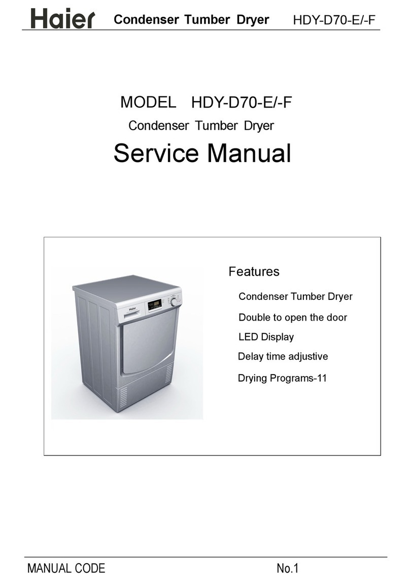
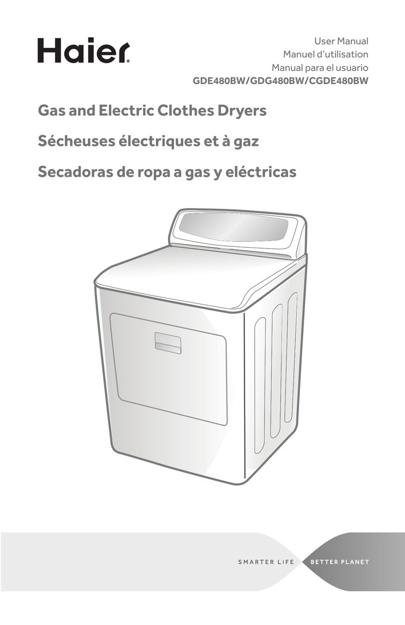
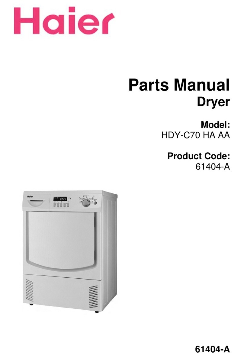
Haier GE GFD14ESSNWW How to use

31-9309
24 Inch Vented Dryer
GFD14ESSNWW
Technical Service Guide
August 2019
Rev. 1 ~ 6/24/20

– 2 –
Safety Information
IMPORTANT SAFETY NOTICE
The information in this service guide is intended for use by
individuals possessing adequate backgrounds of electrical,
electronic, and mechanical experience. Any attempt to repair a
major appliance may result in personal injury and property
damage. The manufacturer or seller cannot be responsible for the
interpretation of this information, nor can it assume any liability in
connection with its use.
WARNING
To avoid personal injury, disconnect power before servicing
this product. If electrical power is required for diagnosis or test
purposes, disconnect the power immediately after performing the
necessary checks.
RECONNECT ALL GROUNDING DEVICES
If grounding wires, screws, straps, clips, nuts, or washers used to
complete a path to ground are removed for service, they must be
returned to their original position and properly fastened.
GE Appliances, a Haier Company
Copyright © 2019
All rights reserved. This service guide may not be
reproduced in whole or in part in any form without written
permission from GE Appliances, a Haier Company.
For Warranty Information:
1. Go to http://products.geappliances.com
2. Search the model number.
3. Click on the Literature tab.
4. Click on Use and Care Manual.
5. Locate the Warranty page.
Warranty

– 3 – (Continued next page)
Table of Contents
Safety Information ........................................................................................................................2
Warranty .......................................................................................................................................2
Table of Contents..........................................................................................................................3
Safety Requirements....................................................................................................................5
Nomenclature ...............................................................................................................................6
Specications ...............................................................................................................................7
Control Features...........................................................................................................................8
Quick Start............................................................................................................................8
Dryer Features......................................................................................................................8
Loading.........................................................................................................................................14
Fabric Care Labels ...............................................................................................................14
Sorting and Loading Hints ....................................................................................................14
Drying Rack ..........................................................................................................................14
Care and Cleaning .......................................................................................................................15
Interior ..................................................................................................................................15
Exterior .................................................................................................................................15
Lint Filler ...............................................................................................................................15
Stainless Steel......................................................................................................................15
Drum Lamp...........................................................................................................................16
Stacking Instructions ....................................................................................................................17
Tools Needed........................................................................................................................17
Installation Preparation.........................................................................................................17
Install Bracket to Washer......................................................................................................18
Install Dryer and Bracket on Dryer .......................................................................................18
Finalize the Installation .........................................................................................................19
Airow...........................................................................................................................................20
Drum and Drive Motor ..................................................................................................................21
Component Locator Views ...........................................................................................................22
Front View Top and Front Panel Removed...........................................................................22

– 4 –
Top View ...............................................................................................................................23
Rear View .............................................................................................................................24
Main Board Connections ..............................................................................................................25
User Interface Board Connections ...............................................................................................26
Capacitive Touch Board Connections...........................................................................................27
Dryer Components .......................................................................................................................28
Control Panel and Front RJ45 Access..................................................................................28
Top Cover .............................................................................................................................28
User Interface Board ............................................................................................................29
Front Panel ...........................................................................................................................30
Door Switch ..........................................................................................................................31
Door Latch ............................................................................................................................32
Drum Lamp...........................................................................................................................32
Outlet Thermistor (NTC1) .....................................................................................................33
Sensor Rods.........................................................................................................................34
Heater Access Panel ............................................................................................................35
Heater Assembly ..................................................................................................................36
Inlet Thermistor (NTC2) ........................................................................................................37
Inlet Thermostat....................................................................................................................37
High Limit Thermostat...........................................................................................................37
Rear Power Outlet ................................................................................................................38
Front Drum Support..............................................................................................................39
Drum Belt..............................................................................................................................40
Motor Drive Belt....................................................................................................................41
Drum and Rear Drum Bearing..............................................................................................41
Motor Assembly ....................................................................................................................42
Main Harness .......................................................................................................................43
Diagnostics and Service Information............................................................................................44
Service Mode Test ................................................................................................................45
Fault Codes ..........................................................................................................................46
Wiring Diagram.............................................................................................................................48
Index.............................................................................................................................................49
– 5 –
Prior to disassembly of the dryer to access components, GE
Factory Service technicians are REQUIRED to follow the Lockout /
Tagout (LOTO) 6 Step Process:
Safety Requirements
Step 1
Plan and Prepare
Step 4
Apply LOTO device and lock
Step 2
Shut down the appliance
Step 5
Control (discharge) stored
energy
Step 3
Isolate the appliance
Step 6
“Try It” verify that the appliance
is locked out
GE Factory Service Employees are required to use safety glasses with side shields, safety gloves and
steel toe shoes for all repairs.
Steel Toed Work Boot
Electrically Rated Glove and
Dyneema® Cut Resistant Glove
Keeper
Dyneema®Cut Resistant
Glove
Cut Resistant Sleeve(s)
Plano Type Safety Glasses
Brazing Glasses Prescription Safety Glasses
Safety Glasses must be
ANSI Z87.1-2003 compliant

– 6 –
Nomenclature
The nomenclature breaks down and explains what the letters and numbers mean in the model number.
Serial Number
The rst two characters of the serial number identify the month and year of manufacture. The letter
designating the year repeats every 12 years.
Example: LA123456S = June, 2013
The Model Serial ID tag is
located behind the door on
the upper left side.
The Mini Manual is located
behind the control access
panel. Remove the screw
cover to access the Phillips-
head screw. Remove the
screw and slide the access
panel to the left.
Model Serial ID
Model Number
Platform
D: Dryer - Standard
G F D 1 4 E S S N 0 W W
Brand
G: GE
Conguration
F: Front Load
Engineering Revision
Alpha or Numeric
Color
WW: White
Model Year
N: 2019
Fuel/Voltage
E: Electric
G: Gas
P: Propane
Series
Product Type
S: Standard/Stationary
Partner Type
S: Standard
A – JAN
D – FEB
F – MAR
G – APR
H – MAY
L – JUN
M – JUL
R – AUG
S – SEP
T – OCT
V – NOV
Z – DEC
2024 – Z
2023 – V
2022 – T
2021 – S
2020 – R
2019 – M
2018 – L
2017 – H
2016 – G
2015 – F
2014 – D
2013 – A
Mini Manual

– 7 –
Specications
Component Approx. Resistance
Motor (CW) 25.3 ± 7%
Motor (CCW) 25.1 ± 7%
Heater 1 (1600W) 34.3 ± 3%
Heater 2 (700W) 75.8 ± 3%
Thermostat TEMP. °F TEMP. °C
Open Close Open Close
Limit 347 ±
16.2%
N/A 175
± 9%
NA
Auto Reset 284 ±
6.3%
257 ±
9%
140 ±
3.5%
125 ±
5%
Inlet Thermistor Resistance
K OHMS TEMP. °F TEMP. °C
11.66 - 12.58 140 60
24.78 - 27.15 104 40
57.30 - 63.85 68 20
Outlet Thermistor Resistance
K OHMS TEMP. °F TEMP. °C
2.41 - 2.57 140 60
5.22 - 5.43 104 40
12.32 - 12.66 68 20

– 8 –
Quick Start
1. Loosely add items, and close the door.
NOTE: The dryer will not start with the door open.
2. If the screen is dark, press the Power button to “wake up”
the display.
3. Select a dry cycle. (Defaults are set for each dry cycle.
These default settings can be changed. See the Control
Settings section in the Use and Care book for more
information.) Or, press the Timed Dry button, rotate the
knob to adjust the time, then press the Temp button to set
a specic temperature.
4. Press the Start/Pause button.
Control Features
Dryer Features
Power
OR
Temp
Timed
Dry
Start
Pause

– 9 –
Dryer Features - Continued
Power
Press Power to “wake up” the display. If the display is active, press Power again to turn the
dryer o. NOTE: Pressing Power does not disconnect the appliance from the power supply.
A
Dry Cycles
The dry cycle controls the cycle time for the drying process. The chart below will help match
the dry setting with the loads.
Mixed Loads
or Normal
(Depending on
model)
For loads consisting of cottons and poly blends.
Cottons For cottons and most linens.
Heavy Duty For large coats, bed spreads, mattress covers, sleeping bags, blankets,
comforters, jackets, small rugs, and similar large and bulky items.
Towels Use for towels OR sheets. It is not recommended to mix towels and
sheets in the same load.
Casuals For wrinkle-free, permanent press and delicate items, and knits.
Active Wear Clothing worn for active sports exercise and some casual wear. Fabrics
include new technology nishes and stretch bers such as Spandex.
Also for clothing labeled Easy Care or Perma Press: For wrinkle-free and
permanent press items.
Sanitize Reduces certain types of bacteria by 99.8%, including: Staphylococcus
aureus, Pseudomonas aeruginosa, and Klebsiella pneumoniae. The
antibacterial process occurs when high heat is used during a portion of
this drying cycle.
Quick Dry For small loads that are needed in a hurry, such as sports or school
uniforms. Can also be used if the previous cycle left some items damp,
such as collars or waistbands.
Delicates For lingerie and special-care fabrics.
Dewrinkle For removing wrinkles from items that are dry or slightly damp. This
cycle is not recommended for delicate fabrics.
Warm Up Provides 25 minutes of warming time to warm up clothes.
Air Flu Provides 30 minutes of tumbling time without heat.
Rack Dry For drying delicate items without tumbling, use a drying rack accessory.
Place items at on the drying rack such as wool sweaters and delicate
fabrics. Dry with low heat.
B

– 10 –
Dryer Features - Continued
Temp
The temperature of the dry cycle can be changed to the following:
High For regular to heavy cottons.
Medium For synthetics, blends and items labeled Permanent Press.
Low For delicates, synthetics and items labeled Tumble Dry Low.
No Heat This option may only be used with Air Flu and Timed Dry, in which items are
tumbled without heat.
C
Level
The sensor continuously monitors the amount of moisture in the load. When the moisture in
the clothes reaches the selected dry level, the dryer will stop.
NOTE: The Sensor Dry Level can be used with all cycles except: Timed Dry, Air Flu, Rack
Dry, Warm Up and Dewrinkle.
Ex Dry Use for heavy-duty fabrics or items that should be very dry, such as towels.
Dry Use for normal dryness level suitable for most loads. This is the preferred
cycle for energy saving.
Damp For leaving items partially damp.
D
Damp Alert
This option causes the dryer to beep when clothes have dried to a damp level. Remove any
items that should be hung to dry. The Damp Alert will only beep when this option is selected,
and the dryer will continue to dry.
Removing clothes and hanging them when they are damp can reduce the need to iron some
items.
E
Timed Dry
1. Select the drying time by pressing the Timed Dry button. Rotate the knob to increase or
decrease the time in 10 minute increments for up to 2 hours and 30 minutes.
2. Select the dry Temp (°C).
3. Close the door.
4. Press Start/Pause.
F

– 11 –
Dryer Features - Continued
My Cycle
Set up a favorite combination of settings and save them in My Cycle for one touch recall.
These custom settings can be set while a cycle is in progress.
To store a My Cycle combination of settings:
1. Select a preferred drying cycle.
2. Change Temp and Level settings to t the needs of the cycle.
3. Select any drying options desired.
4. Press and hold the My Cycle button for 3 seconds to store the selection. A beep will
sound and the button will light up.
To recall the stored My Cycle combination:
Press the My Cycle button before drying a load.
To change the stored My Cycle combination:
Repeat steps 1 through 4.
G
Extended Tumble
• Minimizes wrinkles by adding approximately 2 hours of no-heat tumbling after clothes are
dry.
• The estimated time remaining display will show END.
• The extended tumble time does not get added to the cycle time on the display.
H
eDry (on some models)
Reduces total energy consumption of specic dryer cycles by adjusting certain heat settings.
NOTE: Cycle times will change when eDry is selected.
Energy Star models are tested on Cottons cycle with default settings to determine energy
use of this dryer. The eDry option will default to on for Cottons. Temperature settings on
High and dryness level setting on Dry are specically designed for this cycle to reduce energy
consumption. For optimal energy savings, turn eDry on. For optimal drying times, turn eDry
o. Energy savings will vary across loads and cycles.
®

– 12 –
Dryer Features - Continued
Delay Dry
Use Delay Dry to delay the start of the dryer.
1. Choose a dry cycle and any options.
2. Press Delay Dry. Time can be delayed in 1 hour increments, using the Delay Dry
button.
3. Press the Start/Pause button to start the countdown.
NOTE: If the door is opened while the dryer is in Delay Dry, the countdown time will not
restart unless the door is closed and Start/Pause button has been pressed again.
Start/Pause
Press Start/Pause to start a cycle. If the dryer is running, pressing Start/Pause once will
pause the dryer and unlock the door. This function can be used to add garments during a
cycle. Press Start/Pause again to restart the cycle.
NOTE: If the dryer is paused and the cycle is not restarted within 15 minutes, the current
cycle will be cancelled.
J
Lock
The controls can be locked to prevent any other selections from being made. The controls
can be locked or unlocked after a cycle has been started. Children cannot accidentally start
the dryer by touching pads with this option selected.
To lock the dryer, press and hold the Temp and Level buttons together for 3 seconds.
To unlock the dryer controls, press and hold the Temp and Level buttons together for 3
seconds. A sound is made to indicate the lock/unlock status.
The control lock icon on the display will light up when it is on. NOTE: The Power button can
still be used when the machine is locked.
K
Signal
When the Signal light is on, the dryer will beep at the end of the cycle and every time a
button is pressed on the control panel.
To turn the signal o, press and hold the Damp Alert and Timed Dry buttons together for 3
seconds. A sound is made to indicate the lock/unlock status.
L
M

– 13 –
Display and Status Lights
The display shows the approximate time remaining until the end of the cycle. In addition,
this display will show the dryer status:
Status
Controls locked on.
End of cycle signal on.
Clean Filter Time to clean the lter. See the Care and Cleaning section of this service
guide.
Low Air Indicates decrease in performance of the dryer and increase risk of lint
accumulation in the ducts and dryer.
eDry Shows eDry setting selected.
Temp Shows High, Medium, Low or No Heat temperature setting is selected.
Level Shows Extra Dry, Dry or Damp dryness setting is selected.
Damp Alert Indicates Damp Alert is set and will sound when the clothes have dried to a
damp dryness level.
Dryer Features - Continued
Timed Indicates that a Timed Dry cycle is set. Will turn o after cycle is nished.
Est Time
Remaining
Display shows the estimated time remaining until set cycle is completed.
My Cycle Indicates the My Cycle feature is set.
Ext Tumble Indicates the Extended Tumble feature is set.
Indicates Delay Dry is set time is selected.
DRY DAMP COOL
N

– 14 –
Loading
As a general rule, if clothes are sorted properly for the washer, they are sorted properly for the dryer.
Try also to sort items according to size. For example, do not dry a sheet with socks or other small
items.
Do not add fabric softener sheets once the load has become warm. They may cause fabric softener
stains. Bounce® Fabric Conditioner Dryer Sheets have been approved for use in this dryer when used
in accordance with the manufacturer’s instructions. Do not overload. This wastes energy and causes
wrinkling.
A handy drying rack may be used for drying delicate items such
as washable sweaters. Place items at on the drying rack and
block such items as wool sweaters and delicate fabrics. Dry
with low heat.
To install the drying rack, extend the drying rack into the dryer
drum. Rest the front two legs on the front angled ledge and then
rest the rear two legs on the rear angled edge.
NOTES:
• The drying rack is designed for use with the Timed Dry
cycle. Use with sensor cycles may result in damp items or
extended cycle times.
• Do not use this drying rack when there are other clothes in
the dryer that are not placed on the rack.
• The drying rack (Part #: WE01X26416), is available as an
accessory. Order on-line at GEApplianceParts.com, 24
hours a day or by phone at 877.959.8688 during normal
business hours.
Always follow the fabric manufacturer’s care label when laundering.
Tumble
dry
Dry Normal Permanent Press/
wrinkle resistant
Gentle/
delicate Do not tumble dry Do not dry
(used with
do not wash)
Heat
setting
High Medium Low No heat/air
Special
instructions Line dry/
hang to dry
Drip dry Dry flat In the shade
Tumble
Dry
Heat
Setting
Special
Instructions
Gentle/
Delicate
Dry Do not dry
(Used with do-
not-wash)
Do not tumble dry
Permanent Press/
Wrinkle Resistant
Normal
No heat/airLowMediumHigh
In the shadeLine dry/
hang to dry
Drip dry Dry at
Fabric care label “symbols” that aect the clothing to be laundered:
Fabric Care Labels
Sorting and Loading Hints
Drying Rack

– 15 –
Care and Cleaning
The interior of the appliance and exhaust duct should be cleaned once a year by qualied service
personnel.
• The Exhaust Duct: Inspect and clean the exhaust ducting at least once a year to prevent clogging.
A partially clogged exhaust can lengthen the drying time.
• The Exhaust Hood: Check with a mirror that the inside aps of the hood move freely when
operating. Make sure that there is no wildlife (birds, insects, etc.) nesting inside the duct or hood.
Wipe or dust any spills or washing compounds with a damp cloth. The dryer control panel and nishes
may be damaged by some laundry pretreatment soil and stain remover products. Apply these products
away from the dryer. The fabric may then be washed and dried normally. Damage to the dryer caused
by these products is not covered by the warranty.
To clean stainless steel surfaces, use a damp cloth with a mild, non-abrasive cleaner suitable for
stainless steel surfaces. Remove the cleaner residue and then dry with a clean cloth.
The stainless steel used to make the dryer drum provides the highest reliability available in a GE
Appliances dryer. If the dryer drum should be scratched or dented during normal use, the drum will not
rust or corrode. These surface blemishes will not aect the function or durability of the drum.
Clean the lint lter before each use.
Pull out the lint lter. Moisten ngers and remove the captured
lint. Once clean, slide the lter back into position. Have a qualied
technician vacuum the lint from the dryer once a year.
NEVER OPERATE THE DRYER WITHOUT ITS FILTER IN PLACE.
Interior
Exterior
Lint Filler
Stainless Steel

– 16 –
NOTE: The drum lamp is not consumer replaceable on models where there is a domed cover over an
LED bulb. If this light should ever stop working, call for service.
For models that have a at cover over the bulb secured by a screw:
• Before replacing the light bulb, be sure to unplug
the dryer power cord or disconnect the dryer at the
household distribution panel by removing the fuse or
switching o the circuit breaker. Reach above dryer
opening from inside the drum to locate the light.
• Remove the screw and the plastic cover to access the
bulb. Replace with the appropriate bulb and then reax
the cover and screw.
Order replacement bulb (Part #: WE11X26351) on-line at
GEApplianceParts.com, by phone at 877.959.8688 during
normal business hours, or purchase appliance Bulb 7C7
from a local retailer.
When the door is opened, the drum lamp automatically turns on and remains on for 2 minutes. When
the door is closed, the drum lamp will remain on for 30 seconds.
Drum Lamp

– 17 –
Stacking Instructions
The GE Appliances 24-Inch Dryer is designed
to be placed on top (stacking) of certain 24-Inch
washers. Washer models that currently qualify
for stacking are:
• GFW148
NOTE: If planning to stack the washer and dryer,
order Stacking Kit (Part #: GFA24KITL) to be
used on this dryer. The kit is sold separately.
WARNING!
• Make sure that the dryer is unplugged.
• Two people are recommended to safely lift the
dryer into and out of position.
• Avoid damage to the existing utility services.
Location Requirements
When installed in a location other than an alcove
or closet, the minimal clearances to combustible
surfaces and for air opening are:
• 1-inch on both sides
• 3-inches' front and rear
• 1-inch on top
Consideration must be given to provide adequate
clearance for installation and service.
NOTE: If the dryer is approved for installation in
an alcove or a closet, it will be stated on a label
on the back.
When installed in an alcove or closet:
• The dryer MUST be vented to the outdoors.
• Minimum clearance between the dryer
cabinet and the adjacent walls or other
surfaces is 0 inches' either side, and 3 inches'
front and rear.
• Minimum vertical space from oor to
overhead shelves, cabinets, ceilings, etc., is
67.7 inches.
• Closet doors must be louvered or otherwise
ventilated and have at least 60 square inches
of open area equally distributed. If the closet
contains both a washer and a dryer, the
doors must contain a minimum of 120 square
inches of open area equally distributed.
KIT CONTENTS
(GE APPLIANCES KIT #: GFA24KITL)
• Remove the packaging.
• Flatten the product carton to use as a pad
to lay the dryer down on its side. Continue
using the carton to protect the nished oor in
front of the installation location.
Tools Needed
Installation Preparation
Bracket-
stack (R)
Bracket-
stack (L)
Screws (6) Short
For washer attachment
Screws (2) Long
For dryer
attachment
• Phillips-head Screw-driver
• Level
• Gloves

– 18 –
Install Bracket to Washer Install Dryer and Bracket on Dryer
WARNING:
Disconnect power before installing. Failure to do
so could result in serious injury or death.
WARNING
Excessive Weight Hazard. Failure to do the
following may result in back injury, other injury, or
property damage.
• Use two or more people to install the dryer.
• Avoid tipping and rupture of utility services.
• Dryer must be securely attached to the
washer.
• DO NOT place the washer on top of the dryer.
1. Lift the dryer on top of the washer. Protect
the washer control panel with cardboard or
other protection. Be sure to lift the dryer high
enough to clear the washer control panel.
2. Align the holes in the bracket with the holes in
the back of the dryer. Using a Phillips screw-
driver, attach the two #8 x 1/2-inch tapping
screws.
3. Tighten the dryer bracket screws, then tighten
all stacking kit screws.
1. Remove the washer top cap screw from the
rear left. Align the left bracket holes with the
top cap screw hole on the rear left of the unit
and replace the screw. NOTE: Leave the
screws loose so that the dryer hole alignment
will be easier.
2. Drive the next screw through the bracket into
the rear of the washer.
3. Repeat the above steps with the right side.
Washer
Top
Short screws into
brackets and washer
Long screws into
brackets and dryer

– 19 –
Finalize the Installation
CAUTION
Do not push on the dryer once installed to the top
of the washer. Pushing on the dryer may result in
pinched ngers.
1. Refer to the washer Installation Instructions to
complete the washer installation.
2. Refer to the dryer Installation Instructions to
complete the dryer installation.
3. Carefully slide or walk the stacked washer
and dryer into place. Use felt pads or another
sliding device to assist moving and to protect
the ooring.
Dryer
Washer
Place
hands
here
Place
hands
here

– 20 –
Airow
Airow and Seals
Proper air ow through the dryer is essential for normal operation of the temperature control and safety
systems. Air is PULLED into the cabinet from rear, (1) and drawn across the heaters located behind
the drum (2, 3). This hot air is PULLED through the drum rear (4), across the clothes load (5), through
the lint trap (6), and down the trap duct into the blower (7). From the blower, the air is PUSHED out of
the exhaust system (8, 9).
Any air leaks between the air inlet and the blower, such as lower drum front left or trap duct to cabinet
front sealing, will result in improper temperatures. The air being pulled down the trap duct to the drum
outlet thermostat will be cooler than normal, giving this thermostat a false indication (delayed or no-trip).
Leaks ahead of the blower will also reduce the volume of air across the heaters causing hot spots and
possible premature failure.
Table of contents
Other Haier Dryer manuals

Haier
Haier HD70-01 ME User manual

Haier
Haier HDHP80AN1 User manual

Haier
Haier HD80-79 User manual

Haier
Haier HLP141E User manual

Haier
Haier HLF11PC User manual

Haier
Haier ProSoft User manual

Haier
Haier CG700AW User manual

Haier
Haier HD80-01-U User manual

Haier
Haier HDHP80AW1 User manual

Haier
Haier HLTD500ACW User manual

Haier
Haier HDY-C70 WH HA AA User manual

Haier
Haier GDE480BW User manual

Haier
Haier HDV50E1 Wiring diagram

Haier
Haier HD90-A636-F User manual

Haier
Haier HDM8.0-61 User manual

Haier
Haier HD80-256A User manual

Haier
Haier GDZ5.0-1 User manual

Haier
Haier HLF11PC - 06-04 User manual

Haier
Haier RDE350AW - 6.5 Cu. Ft. Electric Dryer User manual

Haier
Haier HLTD500AGW User manual