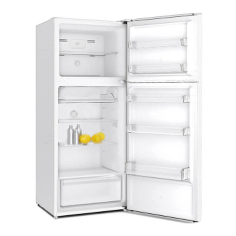
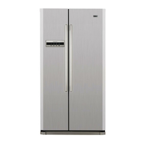
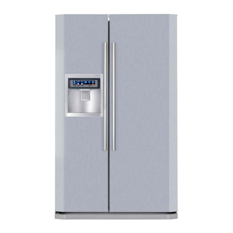
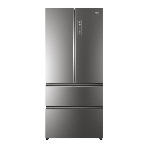
Haier HSM518HMNSS0 User manual

1
Order No. Ref1505S017V0
Refrigerator
WARNING
This service information is designed for experienced repair technicians only and is not designed for use by the general public. It
does not contain warnings and cautions to advice non-technical individuals of potential dangers in attempting to service a product.
Product powered by electricity should by serviced or repaired only by experienced professional technicians. Any attempt to service
or repair the product or products dealt with in this service information by anyone else could result in serious injury or death.
SERVICE MANUAL
MODEL:HSM518HMNSS0
©2015(HAIER ELECTRICAL APPLIANCES COR. LTD)
All right reserved. Unauthorized copying and distribution is a violation of law.
H
●
aier Group
Version: V2
●
●

2
2
●
●
●
Model: HSM518HMNSS0
SERVICE MANUAL
Issue
20200930
REF.
Ref1505S017V0
contents
Chapter 1 General Information.................................................................................................................................... 3
1-1. General Guidelines...............................................................................................................................3
1-2. Insurance test........................................................................................................................................ 3
Chapter 2 Product Feature........................................................................................................................................4
2-1. Specifications........................................................................................................................................ 4
2-2. External view..........................................................................................................................................5
2-3 Space requirement................................................................................................................................ 6
2-4. Main features..........................................................................................................................................6
2-5. Meaning of model number..................................................................................................................6
Chapter 3 Disassembly and Installation................................................................................................................7
3-1 Disassembly of the assembly.............................................................................................................7
Chapter 5 system flow principle............................................................................................................................15
4-1 Refrigerating cycle plan.....................................................................................................................15
4-2 Refrigerating cycle perspective.......................................................................................................15
Chapter 5 Circuit diagram....................................................................................................................................... 16
5-1. Main control Chart.............................................................................................................................. 16
Chapter 6 Main Function Operating principle....................................................................................................19
6-1 Defrost system.................................................................................................................................. 19
6-2 Ice-making control...............................................................................................................................20
6-3 Water Line principle............................................................................................................................ 21
6-4 Adjust the level of the refrigerator.................................................................................................. 21
Chapter 7 Control and display system................................................................................................................ 23
7-1 Control and display panel................................................................................................................. 23
7-2 Function adjustment...........................................................................................................................24
Chapter 8 Quick check and Self-test model....................................................................................................... 31
8-1 Checking method of fault code..................................................................................................... 31
8-2 Test mode.............................................................................................................................................. 33
8-3 Demo mode........................................................................................................................................... 34
8-4 Sensor layout plan.............................................................................................................................. 35
8-5 Water inlet quantity setting............................................................................................................... 37
Chapter 9 Electrical Parts specifications............................................................................................................38
Chapter 10 Trouble shooting..................................................................................................................................39
●
●

3
●
●
●
●
Model: HSM518HMNSS0
SERVICE MANUAL
Issue
20200930
REF.
Ref1505S017V0
Chapter 1 General Information
1-1. General Guidelines
When servicing, observe the original lead dress. If a short circuit is found, replace all parts which have been
overheated or damaged by the short circuit. After servicing, see to it that all the protective devices such as
insulation barriers, insulation papers shields are properly installed. After servicing, make the following leakage
current checks to prevent the customer from being exposed to shock hazards.
1) Leakage Current Cold Check
2) Leakage Current Hot Check
3) Prevention of Electro Static Discharge (ESD) to Electrostatic Sensitive
1-2. Insurance test
1. Check if there is any leak of current.
2. Cut out the power supply before the repair to avoid an electrical shock hazard.
3. In the case of a live-line test, insulating gloves should be worn to avoid potential electrical shock.
4. Confirm the rated current, voltage and capacity before testing with any kinds of instruments.
5. Watch if the upper door is open when you check something at a lower position.
6. Take out every part in the cabinet before moving the machine, especially things like panels (e.g. glass shelf).
7. Please wear intact cotton gloves when repair any parts of the evaporator, so that scratches by the sharp fins
can be avoided.
8. If there is a breakdown with the refrigeration system, please surrender the machine to the service center, else
the leaked refrigerant may pollute the atmosphere.
9. The refrigerator use AC of 115V with a frequency of 60Hz.
10. A big fluctuation of voltage (exceed the range 187~242V) may cause a start failure of the refrigerator, a burn-
out of the control panel and compressor, or an abnormal sound from the compressor in operation. In this
condition an automatic voltage regulator over 60W should be added.
11. Take care not to damage the supply line. Don’t yank at the line; pull the plug out gently from the receptacle.
Don’t press the line under the cabinet or step on it. Take care not to roll on or damage the supply line when
moves the machine from the wall.
12. In the case of leakage of inflammable gases like carbon monoxide, open the door and windows. Don’t pull out
or insert the plugs of the appliance.
13. Don’t touch the refrigeration surface of the freezing compartment when the refrigerator is in operation,
especially when your hand is wet, else you may be glued to the surface.
14. Pull out the plug of power supply during clearance or power outage. Wait at least five minutes to resume the
power supply in order to prevent damage to the compressor caused by continuous restart.
●

4
4
Model: HSM518HMNSS0
SERVICE MANUAL
Issue
20200930
REF.
Ref1505S017V0
Chapter 2 Product Feature
2-1. Specifications
Model
HSM518HMNSS0
1.
Product identification
Description of appliance
Side By Side
Type of appliance(FS = free standing, BI = built-in)
FS
Supplier own brand
Haier
2.
Basic features
●
Climate class
SN.N.ST.T
Gross capacity
l
557
capacity refrigerator compartment
l
331
et capacity freezer compartment (total)
l
169
Freezing capacity
kg/24 h
12
Max storage time by power failure(Freezer)
h
5
Refrigerant
R600a/80g
3.
Control panel
External control display
LED
Temperature range (from>to)
°C
(Fridge)1~9°C/(freezer)-24~-14°C
Power Cool (Fridge)
YES
Power Freeze (Freezer)
YES
Stand-by function (Holiday/Smart)
●
YES
4.
Basics dates
Voltage / frequency
●
115V/60Hz
Input power / mains fuse (intensity)
W /A
200/1.8
Length of cable/incl. plug
cm
349
5.
Packing dimensions
Unit dimensions without handle ( H / W / D)
●
mm
1790*908*655
Net weight
●
kg
100
Packing dimensions (H / W / D)
mm
1890*980*730
Gross weight
kg
114

5
5
Model: HSM518HMNSS0
SERVICE MANUAL
Issue
20200930
REF.
Ref1505S017V0
2-2. External view

6
6
●
●
Model: HSM518HMNSS0
SERVICE MANUAL
Issue
20200930
REF.
Ref1505S017V0
2-3 Space requirement
2-4. Main features
1. Single cooling system with air-cooled computer control, there is a freezer evaporator in freezing room,
fridge room temperature is controlled by ON/OFF of electronic air damper.
2. Super bright LED& energy-saving, brighter& better reliability.
3. Fault code automatically hiding function.
2-5. Meaning of model number
Detailed meaning of all letters and figures of the model number:
H S M 518 H M N SS 0
1st Generation
SS Look
115V/60Hz
Water Dispenser
Ice Maker
Capacity Lt
Mexico + CEAM
Side by side
Haier Brand
●
●

7
7
The fridge
●
sensor
●
Connect the heater
of the damper
③then pull the air duct out.
pull the air duct down
screwdriver
●
②
①Take out the screw (in the
●
red zone) by using cross
Control the
damper
open and
close
Air damper
Connect fridge
sensor
①
②
③
Model: HSM518HMNSS0
SERVICE MANUAL
Issue
20200930
REF.
Ref1505S017V0
Chapter 3 Disassembly and Installation
3-1
Disassembly of the assembly
3-1-1
Disassembly of refrigerator duct

8
8
Model: HSM518HMNSS0
SERVICE MANUAL
Issue
20200930
REF.
Ref1505S017V0
3-1-2
door display panel
Use a screwdriver to tilted the bottom of
the display panel,then remove the whole
display panel.
Bottom of the
display panel

9
9
Model: HSM518HMNSS0
SERVICE MANUAL
Issue
20200930
REF.
Ref1505S017V0
3-1-3
freezer air duct
①First remove the screw cap on the
●
freezer air duct cover (in the red zone),
then take out screw by using cross
screwdriver
●
②Pry the top freezer air duct cover plate
●
with a screw driver then take off the top
of the air duct cover
④seize the both sides of the freezer
fan

10
10
●
●
Model: HSM518HMNSS0
SERVICE MANUAL
Issue
20200930
REF.
Ref1505S017V0
pull out the freezer fan
Take off the connecter of the freezer
fan
Freezer
sensor
④Seize the top of the bottom freezer air
duct cover and pull it then take it off

11
11
Model: HSM518HMNSS0
SERVICE MANUAL
Issue
20200930
REF.
Ref1505S017V0
Defrost heater
connector
Defrost
sensor
connector
When you install the defrost heater,
●
the bottom should be 2 cm far away from
the cabinet, if it is too near, it will
roast the cabinet badly, if it is too
far, the drain hole will be iced up.
Freezer
evaporator
Defrost
heater
Defrost
sensor
fuse
There are 2 fuse on the both sides of
●
the evaporator, they are in series with
the defrost heater

12
12
Model: HSM518HMNSS0
SERVICE MANUAL
Issue
20200930
REF.
Ref1505S017V0
3-1-4
the ambient sensor
Open the right hinge cover, you will find
●
the ambient sensor
●
3-1-5
the cabin
Compressor Cooling fan condenser
The connector of
the cooling fan
①Open the cover of
●
the cabin, you will find
the compressor and
●
the cooling fan
②use a flat
●
screwdriver pry the
Compressor
accessories cover, we
can take off the
accessories

13
Model: HSM518HMNSS0
SERVICE MANUAL
Issue
20200930
REF.
Ref1505S017V0
3-1-6
Disassembly of the ice maker
①Take out ice storage box and shelf;
②Remove the 2 screws at the top of the
●
front, pull slightly, after the ice maker
assembly separate with the top of
refrigerator, the connector terminal
●
appears at the left side of the back,
●
separate the connector terminal then
take out the ice maker assembly.
●
Note: the movement range can not be
too large, in case damage the cable
jumper.
3-1-7
Disassembly of water tank cover and water tank
①Put your fingers into the
disassembly mouth of the water
tank cover as shown in the
●
picture, pulling slightly ramp
above is able to loosen the snap
joint of the water tank cover.
②Grasp the loosened water tank
cover, pulling slightly towards the
left as shown in the picture is
able to take down the water tank
cover from the door.

14
14
③Hold down the fixed card towards
the water tank, pull out the two
pipes.
Note: before pulling out the pipes,
please empty water in all pipes of
the refrigerator, in case the water
●
saptters.
●
④Remove two fixed screws under
the water tank, pull towards the
right is able to take down the water
tank from the door.
Model: HSM518HMNSS0
SERVICE MANUAL
Issue
20200930
REF.
Ref1505S017V0
3-1-9 Assembly of water tank and water tank cover
1.Install the water tank on the door, fix the water tank with two screws 0060600097 at the bottom, do not pin the
two pipes.
2.Connect the white pipe to the left faucet of the water tank, and connect the blue pipe to the right faucet of the
water tank, please make the color code cling the fixed card, make it water-tight.
3. Fix the water tank cover: ①Incline the water tank cover towards the operator, firstly install the right to the boss
on the door; ②Push the left side of the water tank cover towards the door to make the jack catch get stuck in
the columnar side of the water tank; ③Pat upside of the water tank cover until the jack catch get stuck in the
upper snap joint, mean that the upside of the water tank cover is not loose; ④Pat downside of the water tank
cover until the jack catch get stuck in the lower snap joint, mean that the downside of the water tank cover is not
loose, there is no gap between the door and water tank cover.

15
15
●
Model: HSM518HMNSS0
SERVICE MANUAL
Issue
20200930
REF.
Ref1505S017V0
Chapter 5 system flow principle
4-1
Refrigerating cycle plan
4-2
Refrigerating cycle perspective

16
16
Model: HSM518HMNSS0
SERVICE MANUAL
Issue
20200930
REF.
Ref1505S017V0
Chapter 5 Circuit diagram
5-1. Main control Chart

17
17
CN19
●
CN18
CN13
CN12
CN11
CN10
CN21
CN1
CN2
CN3
CN6
CN8
Model: HSM518HMNSS0
SERVICE MANUAL
Issue
20200930
REF.
Ref1505S017V0
Connectors ‘ location on PCB
CN20
●

18
18
Model: HSM518HMNSS0
SERVICE MANUAL
Issue
20200930
REF.
Ref1505S017V0

19
19
●
●
●
●
Model: HSM518HMNSS0
SERVICE MANUAL
Issue
20200930
REF.
Ref1505S017V0
Chapter 6 Main Function Operating principle
6-1
Defrost system
6-1-1
defrost control :
According to the times of opening and closing the door and the time of the compressor cumulative
working, the refrigerator has different frost timing . When the temperature of the defrost sensor reaches
7℃,the defrost stops, in defrosting the compressor and freezer fan are off, the refrigeration damper
closes.
If the defrost time reaches 70 minutes, but the temperature of the defrost sensor does not reach 7℃,
then the defrost heater is off, Ed displays.
6-1-2. the easily broken part in the defrost system :
1)Defrost fuse, it is on the middle of the evaporator, outer is plastic bushing, normally, it is conducting.
If it is open, it is broken.
2)The connection between the defrost fuse or defrost heater and cabinet, if the connection terminal
falls off or decline, poor contact will happen.
3)Defrost sensor, which locates at the top right
6-1-3. defrost rule
RT(℃)
Time
Defrost condition
RT<23
Compressor accumulative
running time:7H<T≤12H
R.door open accumulative time ≥9min ,Defrost Immediately
Compressor accumulative
running time:T>12H
●
R.door open accumulative time ≥3min ,Defrost Immediately;
Refrigerator accumulative
running time =50H
Defrost Immediately
23≤RT≤28
Compressor accumulative
running time:7H<T≤12H
R.door open accumulative time ≥9min ,Defrost Immediately
Compressor accumulative
running time:T>12H
R.door open accumulative time ≥3min ,Defrost Immediately;
Refrigerator accumulative
running time =72H
Defrost Immediately
28<RT<
35
Compressor accumulative
running time:7H<T≤12H
R.door open accumulative time ≥9min ,Defrost Immediately

20
20
●
Model: HSM518HMNSS0
SERVICE MANUAL
Issue
20200930
REF.
Ref1505S017V0
Compressor accumulative
running time:T>12H
R.door open accumulative time ≥3min ,Defrost Immediately;
Refrigerator accumulative
●
running time=50H
Defrost
Immediately
35≤RT<41
Compressor accumulative
running time:7H<T≤12H
R.door open accumulative time ≥9min ,Defrost Immediately
Compressor accumulative
running time T>12H
●
R.door open accumulative time ≥3min ,Defrost Immediately;
Refrigerator accumulative
running time =21 小时
Defrost
Immediately
RT≥41
Compressor accumulative
running time:7H<T≤12H
R.door open accumulative time ≥9min ,Defrost Immediately
Compressor accumulative
running time:T>12H
R.door open accumulative time ≥3min ,Defrost Immediately;
Refrigerator accumulative
running time =21 小时
Defrost
Immediately
6-2
Ice-making control
2.Ice maker testing: Under locked state,press”Ice”+”Lock” for 3 sec.,when the beep sound,open FRZ
door,within 20 sec.ice maker turns out automatically.
Table of contents
Languages:
Other Haier Refrigerator manuals

Haier
Haier HBM450WH1 User manual

Haier
Haier BCD-259DVC User manual

Haier
Haier A3FE737CPJM User manual

Haier
Haier HRF-285 User manual

Haier
Haier HRF-663ISB2 Series User manual

Haier
Haier HT18TS45SW User manual

Haier
Haier HE7195BCMW User manual

Haier
Haier BC-117A Series User manual

Haier
Haier HRF328W2 User manual

Haier
Haier NRF135N2 User manual

Haier
Haier HDE03WNA User manual

Haier
Haier HTF-540DGG7 User manual

Haier
Haier HTF-452WM7 User manual

Haier
Haier HR-170T/A User manual

Haier
Haier HXC-158B User manual

Haier
Haier LSA02W User manual

Haier
Haier HRFN-250DAA User manual

Haier
Haier HRF12WNDWW User manual

Haier
Haier HB21TNN User manual

Haier
Haier HTF-452D 7 Series User manual