manuals.online logo
Brands
  1. Home
  2. •
  3. Brands
  4. •
  5. Haier
  6. •
  7. TV
  8. •
  9. Haier L32A7A-A1 User manual

Haier L32A7A-A1 User manual

Other Haier TV manuals

Haier 21F99 User manual

Haier

Haier 21F99 User manual

Haier HTR20-A User manual

Haier

Haier HTR20-A User manual

Haier HL15T Building instructions

Haier

Haier HL15T Building instructions

Haier HTX25S31, HTX29S31S, HTX34S31 User manual

Haier

Haier HTX25S31, HTX29S31S, HTX34S31 User manual

Haier LE24P610 User manual

Haier

Haier LE24P610 User manual

Haier SA21XT User manual

Haier

Haier SA21XT User manual

Haier 29FA10 User manual

Haier

Haier 29FA10 User manual

Haier L40F1180 Assembly instructions

Haier

Haier L40F1180 Assembly instructions

Haier HTN13R12 User manual

Haier

Haier HTN13R12 User manual

Haier TV-8888-09 User manual

Haier

Haier TV-8888-09 User manual

Haier HL22R3 User manual

Haier

Haier HL22R3 User manual

Haier L37K30B User manual

Haier

Haier L37K30B User manual

Haier 29FV5H User manual

Haier

Haier 29FV5H User manual

Haier L32D1120 Assembly instructions

Haier

Haier L32D1120 Assembly instructions

Haier 43B3Y-N Quick start guide

Haier

Haier 43B3Y-N Quick start guide

Haier L26A9A User manual

Haier

Haier L26A9A User manual

Haier LT22R3COW User manual

Haier

Haier LT22R3COW User manual

Haier L1527 User manual

Haier

Haier L1527 User manual

Haier L42A9 User manual

Haier

Haier L42A9 User manual

Haier HLC22R User manual

Haier

Haier HLC22R User manual

Haier HTX20S32 User manual

Haier

Haier HTX20S32 User manual

Haier HL42K User manual

Haier

Haier HL42K User manual

Haier HS-2190

Haier

Haier HS-2190

Haier 21FA11 User manual

Haier

Haier 21FA11 User manual

Popular TV manuals by other brands

IKEA UPPLEVA user manual

IKEA

IKEA UPPLEVA user manual

Toshiba 19A20 Service manual

Toshiba

Toshiba 19A20 Service manual

Sony XBR-100Z9D reference guide

Sony

Sony XBR-100Z9D reference guide

Sony Trinitron KV-HR36M90 Service manual

Sony

Sony Trinitron KV-HR36M90 Service manual

JVC AV-14AG16 instructions

JVC

JVC AV-14AG16 instructions

Loewe Table Stand Reference 55 user guide

Loewe

Loewe Table Stand Reference 55 user guide

Panasonic Genus TX-G10 operating instructions

Panasonic

Panasonic Genus TX-G10 operating instructions

Samsung LN26C350D1D Service manual

Samsung

Samsung LN26C350D1D Service manual

BBK LT1516D Service manual

BBK

BBK LT1516D Service manual

Samsung 55S9 B Series Quick setup guide

Samsung

Samsung 55S9 B Series Quick setup guide

Sharp LC-40FI5012E user manual

Sharp

Sharp LC-40FI5012E user manual

Evervue BN185 Operation manual

Evervue

Evervue BN185 Operation manual

North State TV2GO user guide

North State

North State TV2GO user guide

Toshiba CX35F70 owner's manual

Toshiba

Toshiba CX35F70 owner's manual

Magnavox PS1980 owner's manual

Magnavox

Magnavox PS1980 owner's manual

Philips 20HF5335D manual

Philips

Philips 20HF5335D manual

Panasonic QuintrixF TX-29AS1D operating instructions

Panasonic

Panasonic QuintrixF TX-29AS1D operating instructions

Samsung 4 Series Quick setup guide

Samsung

Samsung 4 Series Quick setup guide

manuals.online logo
manuals.online logoBrands
  • About & Mission
  • Contact us
  • Privacy Policy
  • Terms and Conditions

Copyright 2025 Manuals.Online. All Rights Reserved.

L32A7A-A1
Contents
1. Summarize
2. Main features
3. Appearance picture of complete set
4. Chassis appearance picture
5. Interface definition and interface electric requirements
6. Factory mode instructions
7. Structure size
8. The requirements of transportation, storage and usage
9. Appendix
1. Summarize
this chassis is used to match and connect the big screen LCD TV, it supports multi-system TV input signal ,
it can stored 256 TV programs at most, at the same time the highest resolution of this chassis can be up to
SXGA or appear R, G, B input signal of WXGA of 16:9 again, color appear again can support 24 bit, and it
can realize synchronous automatic check. It can support 1080P HD signal input at most, and includes two
rows CVBS signal, one row S terminal signal input, one row HDMI signal one row CVBS signal output.
Inbuilt 2x10W medium sound + 2x3W treble sound output, four rows two channels external audio signal
input, one row sound output. Support left and right sound balance, equalizer adjustment function.
Meanwhile, this chassis can support TV signal and PIP display in HD signal at the same time, and there are
3A picture optimise, 3A demo.
2. Main Features
LCD TV control panel support specifications:
The sound box part and the structure of complete set is separable,so it need install solely.
4. Appearance picture of chassis
5. Interface definition (see appendix 2) and interface electric requirements
1. Power interface: supply the working power to chassis from power board..
2. Background light control panel interface: control the switch and brightness of screen background light
S-VIDEO input
PC audio input
VGA input
Power input
socket
Key control
socket
Screen connecting
Wire socket
Background light
control interface
Up grading
socket
CVBS input
AV1video input
AV video output
Speakeroutput
Remote control
socket
(down)HD signal input
AVaudio output
AV1audio input
HD signal audio input
Earphone socket
The speaker power socket
HDMI input
Side AVsocket
3. Remote control interface: support Toshiba receiving negotiation.
4. Control panel interface: 7 button control.
5. Sound output interface: sound signal output.
6. Program upgrading interface: upgrading program. Only for factory use.
6. Factory mode instructions
This chassis use new HYF-35R remote controller (grey, 41 button, can not share with the original blue 35
button HYF-35R ), the method to enter the factory mode is: Screen-----P.STD------S.STD------Sleep Time.
The following is the instructions of the factory menu of V2.1 version program.
WHITE BLA White, dark balance adjustment
Name Description
R OFF
G OFF
B OFF
Whitebalanceadjustment
R GAIN
G GAIN
B GAIN
Darkbalanceadjustment
AUTOTUNE Automaticadjustment
FACTORY SET
Name Description
POWER STB ON: power standby OFF: standby memory
NOSYNC LOGO Screen saver without signal ON: open OFF: close
BACK LIGHT Background light brightness adjustment of screen: 0-255
DLC TEST Automatic brightness control switch 1:open 2:close
TV BACK SCREEN Background without signal BLUE: blue screen BLANK: blank screen
MCLK SDRAM : clock impulse 120-166 we recommend not
adjusting.
PIP SIZE PIP dimension MIDDLE: medium dimension LARGE: large dimension
INITEEPROM InitializeEEROM
INITTV Initialisedfactorysignal donotuse
PICTURE MODE Parameter of picture mode adjustment
COLOR TEMP Parameter of color temperature adjustment
SOUND MODE Parameter of sound mode adjustment
Never adjust the following other items
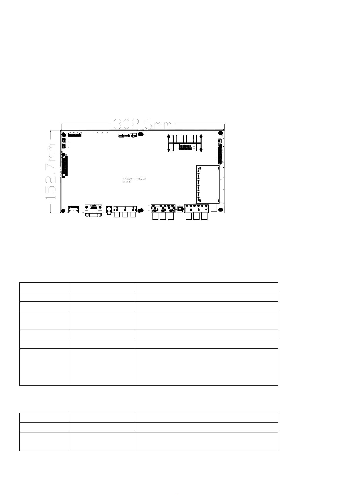
7. Structure dimension (see appendix 1)
Relevant dimension specifications of control panel PCB,The specification of screw hole: diameter 3.3mm
screw hole , the structure diagram of hole position
8. Transportation, storage and usage requirements
1. Never press heavily and bend
2. Eliminated static
3. Relative humidity: below 80%
4. Storage temperature: -10¬+40℃
5. Usage temperature: 0¬+40℃
9. Appendix
Appendix 1: the dimension diagram of structure
Appendix 2: interface definition table
XP600 (9PIN/2.5): Power interface
NO. Definition Description
1 STN Power-on signal(high-level is available)
2 GND Ground
3 5V CPU working voltage(standby but not power
off)
4 GND Ground
5 GND Ground
6
7
8
9
GND
12V
12V
12V
Ground
Chassis working power (standby but power off)
XP601 XP601A (3PIN/2.0):Background light control interface
NO. Definition Description
1 ADJ Background light brightness control
2 ON/OFF INVERTER ON/OFF (high level is
available )
3 GND Ground
XP501(4PIN/2.0): Remote control button interface
NO. Definition Description
1 IR Remotecontrolreceiving
2 +5V 5VPower
3 GND Ground
4 LED Powerindicatorcontrol
XP502(4PIN/2.0):
NO. Definition Description
1 KEY1 Control panel signal 1
2 GND Ground
3 KEY0 Controlpanelsignal2
4 GND Ground (air connect)
XP301 (Right sound), XP302 (left sound) (2PIN/2.5): Sound output interface
NO Definition Description
1 SPK+ Sound output signal +
2 SPK- Sound output signal -
XP503 (4PIN/2.5):
NO. Definition Description
1 5V CPU Power
2 GND Ground
3 RXD Signal interface
4 TXD Signal interface
L32A7A-A1
Drafted by:Chen Long Checked by:Peng You Approved by:Hu Xijia
User’s Manual
①
NO Power
Check power board 24V supply See background light is not on partCheck power board 12V supply
CPU is damaged replace
Check power board 5V supply
Check CPU Power-on signal
Check power boardAC input
Power boad is damaged,replace
Check and repair Power input part
with
with
with
with
with
without
without
without
without
without
②
Video Without Signal
TV Without
Check tuner 5V supple
Check if the bus control is normol
Check if the tuner is output
Check if the signal is input the
picture decode chip
Check if the chip supple,crystal
osciuator or bus control is normal
Chip is damaged,replace
Check and repair 5V supple part
Deck and repair bus control part
Tuner is damaged,replace
Check and repair if the signal
circuit is erroneous
Check an repair the chip relevant
circuit
with
without
Yes
Yes
Yes
Yes
Yes
No
No
No
No