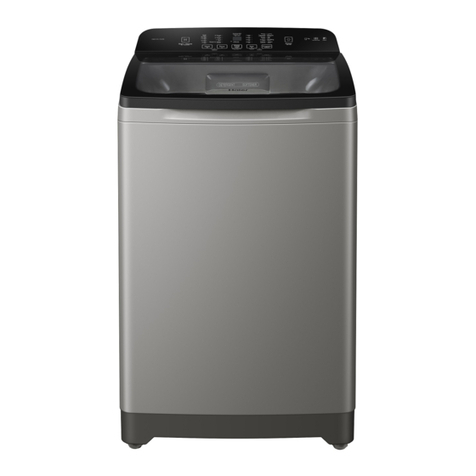
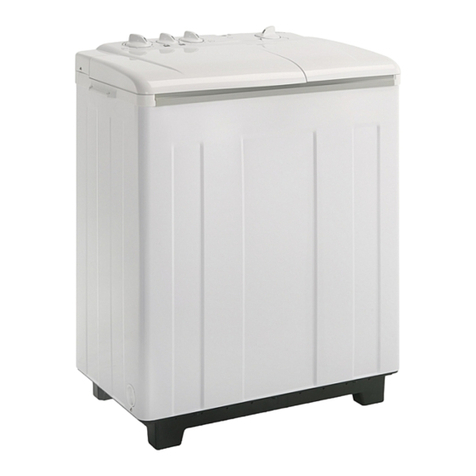
Haier XPB10-LAP User manual

SERVICE MANUAL
XPB10-LAP
TWIN TUB WASHING MACHINE
WD-8888-89
HAIER AMERICA TRADING, LLC
www.Haieramerica.com
WD-8888-89

1.Contents 1
2.
3. Specifications 3
4.
5. 5
6. Net dimension 6
7. 6
8. Parts 10
9. Maintenance service and trouble shooting 11
10. Wiring diagram 14
11. Exploded view 15
12. List of parts 17
Features 2
Safety precautions 4
Warning and cautions
Installation and accessory parts
1
CONTENTS
Model:XPB10-LAP

Features
2
FEATURES
Model:XPB10-LAP
Super large capacity, washing more clothes;
Dish-pattern big wave wheel, stronger water flow;
The drain and overflow adopt straight tube structure against the blocking;
Separate water injection structure, more convenient switch between the
water injections for washing, rinsing and spin.

SPECIFICATIONS
Model:XPB10-LAP
3
Model XPB10-LAP
Free standing
Built under ×
EAN c ode
Energy efficienc y c lass —
Features for use
Was h capacity Kg 10
Spin c apacit y Kg 7
Level/Volume LHigh/about99L m edium/about 77L low/about65L
Preset H×
Residual dam pness %115
Control model Tim er
controller ×
Normal com puterized ×
Fuzz y c omputeriz ed ×
Frequency conversion ×
Service features
Programs 2
Short cycle ×
Inlet heating select
Heating selection ×
Spinning c yc le (selec tor) ×
Spinning c yc le (variable) ×
Start/Pause ×
Autom atic balancing ×
Aesthetic s High head
Cabinet mat erial P=Plastic/Z=Zincking/C=Cold ) Z
Rolled stainless steel
Inner drum(stainles s s teel=s /plas tic=p) P
Drain type Down
Door (glass= g / plas tic=p) ×
Adjus table feet ×
Technical dat a
Voltage/ frequency V/Hz 120/50
Energy c onsumpt ion kWh
Wat er consum ption L
Was h power W280
Spin power W170
Special function
Air-Bubble ×
Feet wheel ×
Wat er fall current ×
Dimens ions (meas urements )
Height / built under mm 986
Width mm 876
Depth / with open door mm 500
Dimensions pac ked ( meas urements packed)
Height cm 1040
Width cm 940
Depth cm 578
Net weight kg 35.5
Gross weight kg 40
20'Container load Sets 44
40’Container load Sets 88
40H’Container load Sets 124
NOTE: " " FOR AVAILABLE, "×" FOR NOT AVAILABLE “-”FOR NOT APPLICABLE

SAFETY PRECAUTIONS
If the power cord is bad, to avoid risk it is required to replace it by the technicians of
our special shop or the after-sale service department. Keep the pin of the power
plug clean.
Please insert the power cord into special
receptacle with rated voltage. Be sure to
use single-phase two pins receptacle.
The earthing terminal must be earthed
reliably. If possible, please adopt electric
leakage protector.
When the machine is normally using, please
put the power plug at the location easily to
be inserted and extracted by hand. Be sure
to pull the plug off when the power failure,
or the machine is being moved, cleaned or
when it is idle.
In case the washing machine is installed
on ground with carpet , do not block the
ventilation hole with carpet.
Ventilation hole at
the bottom of the
washing machine
Do not use water hotter than 50 C .
Do not share one receptacle with other
electric appliances. Do not use it in
case that the power plug is damaged
or the inserting into the receptacle is
loose.
Do not wash water-proof laundries such
as the raincoat, bicycle shelter etc. To
avoid abnormal vibration during spinning.
Do not put the machine at damp place
like the bathroom . Never wash it with
water. Do not place wet laundries on the
control panel.
4
Model:XPB10-LAP

Do not stretch hands into the working
machine. It is dangerous even if the
rotation is slow. Take special care of
the children.
Handicapped or children without care
shall not use the machine.
Do not put any hot or heavy items
( such as the kettle with hot water )
on the washing machine.
Do not decompose, repair or alter the
machine by yourself.
Keep the machine away from direct
sunlight and heat source like the
heater.
Do not wash laundries with volatile
materials (such as thinner, petrol etc.).
Petrol
Thinner
WARNING AND CAUTIONS
5
Model:XPB10-LAP

Figure 1
NET DIMENSION
INSTALLATION AND ACCESSORY PARTS
Unit mm
6
Model:XPB10-LAP
The drainage shall be smooth with the drain hose.
1.The height of the drain hose shall be
less than 10cm , or the drainage will
not be smooth enough and cause
incomplete drainage.
2.Do not step on or press the drain hose.
3 If the drain hose is too long, cut it at mid
point. To make smooth drainage, cut the
front end of the hose slantingly.
The drainage shall be smooth with the drain hose.
<10cm
m
<1.5m
1.The height of the drain hose shall be
less than 10cm , or the drainage will
not be smooth enough and cause
incomplete drainage.
2.Do not step on or press the drain hose.
3 If the drain hose is too long, cut it at mid
point. To make smooth drainage, cut the
front end of the hose slantingly.
The drainage shall be smooth with the drain hose.
1.The height of the drain hose shall
be less than 10cm. or the drainage
will not be smooth enough and cause
incomplete drainage.
3.If the drain hose is too long, cut
it at mid point. To make smooth
drainage, cut the front end of
the hose slantingly.
2.Do not step on or press the drain hose.
4.IF extra drain hose is needed,
please make separate purchase.
The inner diameter of the extra
hose shall be not less than
30mm, and the length shall
be not exceed 1.5m.

How to change the direction of the drain hoses
INSTALLATION AND ACCESSORY PARTS
7
Model:XPB10-LAP
Extend the drain hose from the rear side
Figure 1 indicates the ex factory installation
position of the drain hose.
Put soft items on the ground. Lean the machine
down gently with the front surface facing the
ground. Take off the drain hose from the cabinet.
Dismantle the drain hose fixing clamp and take
the hose out of the fixing groove.
(See to Figure 2).
Embed the drain hose into the groove along the side
of the spin tub in the order of (1)~(3), heading for the
side of the spin tub. (See to Figure 3).
Embed the drain hose into the groove with
hands. Take care not to damage the drain
hose in fastening the fixing clamp.
Figure 1
Figure 2
Figure 3
Figure 4
Embed into the
groove in turn
Back
Extend the drain hose from the side of spin tub
Soft item
Soft item
Extend to the
spin tub side
Dismantle the drain hose fixing clamp.
Take out the drain hose from the fixing groove.
Extend it from the rear side as per the direction
of the arrow. (When the drain hose is extended
from the rear side, it can be hung on the point
for drain hose at the two sides of the cabinet.)
(See to Figure 4).
Front
Drain hose fixing clamp

Spin tub shaft
Bearing seat
Figure 8
Oilite bearing
Inner lining of
the bearing seat
Fastening screw
Fastening screw of
the brake wheel
Inner lining of the
brake wheel
Brake wheel
Spin motor shaft
Points of Attention in After-sales Service
Be sure to switch off the power during dismantling or repair.
Be sure to use insulated wiring terminals and insulation box in connection of the wires, and
crimp and fix to proper position with suitable tools.
In welding connections with electric iron, be sure to twist the wires before welding, and insulate
with insulation tapes.
In welding the wires with electric iron, be sure not to touch the resin part and insulation part of
each switch.
The inlay connection wires and terminals shall not be loose or drop.
Do not make the wires touch the moving parts like the belt, pulley of the motor, brake bar etc.
Do not make the wires touch the sharp edges and high-temperature area.
In case that there are metal parts with the wires, do not make the wires touch the metal parts.
Insulation materials are needed between them.
After assembly, the washing machine shall act normally. Check if it leaks and if the sound and
vibration are normal.
Dismantling and installation of the control panel component
Loosen the fastening screws. Pull towards the direction
indicated in the figure to dismantle the control panel. In
installation the beard shall lock into the installation hole
of the major frame. (Figure 6)
Dismantling and installation of the spin tub
frame component
Push the points marked with " " as indicated in
the figure and pull the spin tub frame towards
upper left direction to dismantle the spin tub frame
components. In installation, after set the rear side
of the spin tub frame to proper position, push the
four points marked with " " downwards by force
to resume its original position. (Figure 7)
Dismantling and installation of
the spin tub
Dismantle the spin tub frame component.
Loosen the fastening screw of the spin tub
shaft. The spin tub then can be taken out.
In installation, be sure to inlay the bulge of
the inner lining of the brake wheel into the
groove of the spin tub shaft. (Figure 8
Figure 6
Spin tub frame
Dismantle Installation
Figure 7
INSTALLATION AND ACCESSORY PARTS
8
Model:XPB10-LAP
Adjust the tension of the belt
Loosen the fastening screw at the back of the
base frame. Move the shift fixing gasket along
the direction indicated in the figure to adjust
the tension of the belt. After adjusting, fasten
the screw. (Figure9)
Dismantling and installation of the base frame
Dismantle the back cover. Loosen the wires. Loosen the
fastening screw of the spin tub shaft. Separate the shaft
from the brake wheel. Loosen the brake hook. Take off
the brake cable frame from the installation groove of the
twin-tub. Take off the V-belt. Take out the drain hose from
the groove of the base frame. Loosen the fastening screw
between the base frame and the cabinet to dismantle the
base frame component.
Dismantling and installation of the bearing seat
Once the bearing seat is taken off, it can not be utilized again. Therefore do not dismantle
it as far as possible. In case that it has to be replaced, please dismantle it as per following
sequence, then install a new bearing seat.
Dismantle the spin tub as per Clause 9.4. Then pull out the bearing seat.
Cut off the inner lining claw inside the bearing seat with cutting pliers and take it out.
Install the new bearing seat and inner lining.
The bearing seat is an inlay component. Be sure to aim the claw of the inner lining at the
hole of the tub then push it in. Please use suitable tools and add even pressure around
the tub.
After inlay the bearing seat, check if the claw is installed to proper position from the outside
of the twin-tub (Figure 10).
Figure 9
Figure 10
Right Wrong
INSTALLATION AND ACCESSORY PARTS
9
Model:XPB10-LAP

PARTS AND FUNTIONS
10
Model:XPB10-LAP
Outer cover of the spin tub
Inner cover of the spin tub
Spin timer
Spin tub frame
Spin tub
Cabinet
Power cord
Water-filling entrance
Water inlet selector handle
Buzzer
Wash selector
Wash timer
Control panel
Filter frame
Lint filter
Wash tub
Pulsator
Drain hose
Base frame
Wash tub cover

8. Analysis Of The Common Breakdown
MAINTENANCE SERVICE AND TROUBLE SHOOTING
11
Model:XPB10-LAP
YES
YES
YES
YES
YES
YES
YES
Insert the power plug , but the machine does not work
Switch on the power.
Replace the plug
or receptacle.
Replace with new power
supply cord.
Replace the fuse.
Inlay the connecting
wire again.
Check if the motor is good?
Replace the motor
Replace the wash timer
Replace the capacitor
Check if the capacitor
is good?
Poor contact or inferior
inside of the wash timer
Open the wash timer.
Check if the power source is available?
Check if the contact between
the plug and receptacle is good?
Check if the power supply
cord is good
Check if the fuse is good?
Check if the wash timer is opened ?
NO
NO
NO
No
NO
NO
NO
NO
NO NO
Check if the inlay of
the connecting wire
terminal is good?
Wash part

MAINTENANCE SERVICE AND TROUBLE SHOOTING
Spin part
Check if the brake system
is detached?
Repair the brake system.
Check if the spin timer
is opened ?
NO
YES
NO
YES
NO
YES
NO
YES
NO
YES
NO
YES
NO
YES
NO
NO YES
YES
NO
Switch on the power.
Open the spin timer.
Check if the power source
is available?
Replace the plug
or receptacle.
Replace with new
power supply cord.
Check if the contact between
the plug and receptacle is good?
Check if the power supply
cord is good?
Replace the fuse.
Inlay the connecting
wire again.
Check if the fuse is good?
Check if the micro-switch is closed?
Check if the inlay of
the connecting wire
terminal is good?
Replace the capacitor.
Check if the capacitor
is good?
Replace the motor.
Repair the micro-switch,
make it closed.
Check if the motor is good
Model:XPB10-LAP
12

MAINTENANCE SERVICE AND TROUBLE SHOOTING
If the brake arm
has brake block ?
Is the motor noise large?
Is the motor fastened tightly?
Is the belt too loose
or too tight?
Replace the wash timer
Is the wiring of
the wash timer proper?
Is the radiating pulley loose?
Is the pulsator rubbing the
bottom of the twin-tub?
There is metal rubbing noise in braking
The washing noise is too large
The pulsator only rotates towards one direction
NO
YES
NO
YES
YES
YES
NO
YES
NO
NO
Add the brake or replace
the brake arm.
Replace the motor.
Fasten the motor tightly.
Adjust the tension of the belt.
Fasten the radiating pulley.
Adjust the gap between the
pulsator and the twin-tub.
Adjust the wiring to
proper position.
YES
NO
13
Model:XPB10-LAP

Actual Circuit Diagram
There is overload protector installed in the motor. In case that the motor is overload or meets
breakdown in working, the protector will act and stop the motor. When the breakdown is
removed, the motor will resume normal working.
Figure14
WIRING DIAGRAM
Figure 13
14
Model:XPB10-LAP
spin timer
safety switch
orange
purple
purple
grey
grey
spin
motor
blue
blue
blue
wash
motor
red
yellow
wash timer
C1
C2
S2
S1
a
b
fuse
brown
buzzer
M
M
spin timer
microswitch
buzzer
wash timer
wash
motor
capacitor
fuse
red
red
red
yellow
yellow
gray
gray
gray
gray
brown
brown
brown
blue
Yellow/green
orange
orange
purple
purple purple
blue
yellow
blue
Cabinet
Control
Panel
spin
motor
Other manuals for XPB10-LAP
1
Table of contents
Other Haier Washer manuals

Haier
Haier HWMSP60 User manual

Haier
Haier HWF5000AW Assembly instructions

Haier
Haier HWM80-0528 User manual

Haier
Haier HW-D1470TVE ME User manual

Haier
Haier WMS656 User manual

Haier
Haier HWM60-0523S User manual

Haier
Haier HWM75TL User manual

Haier
Haier HVS1200ME User manual

Haier
Haier HW80-B14979 User manual

Haier
Haier XQG50-800TXB User manual

Haier
Haier HWM55-7288P User manual
Haier
Haier HWM55-0528 User manual

Haier
Haier HWM45-187S User manual

Haier
Haier HWM130-9188DD User manual

Haier
Haier XQSB60-JN User manual

Haier
Haier LMD3123PBEB0 User manual

Haier
Haier HWM180-M1990DD User manual

Haier
Haier HWM75-276S User manual

Haier
Haier SSW 800E User manual

Haier
Haier HW100-B14266A User manual