Hakko Electronics FN-1201 User manual

Connection Box
Instruction Manual
Thank you very much for purchasing
the HAKKO FN-1201 (Connection Box).
Be sure to read this manual before operating
the HAKKO FN-1201.
Keep this manual readily accessible for reference.
FN-1201

ii
Table of Contents
1. PACKING LIST .....................................................................................................................1
2. SPECIFICATIONS ................................................................................................................1
3. WARNINGS, CAUTIONS AND NOTES................................................................................2
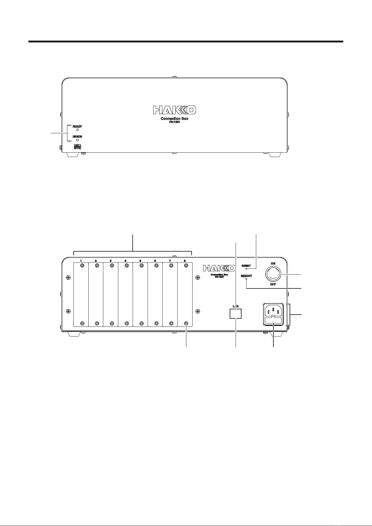
4. PART NAMES.......................................................................................................................3
4-1 Front View................................................................................................................................................. 3
4-2 Rear View .................................................................................................................................................. 3
5. INITIAL SETUP .....................................................................................................................4
5-1 Installing interface cards........................................................................................................................ 4
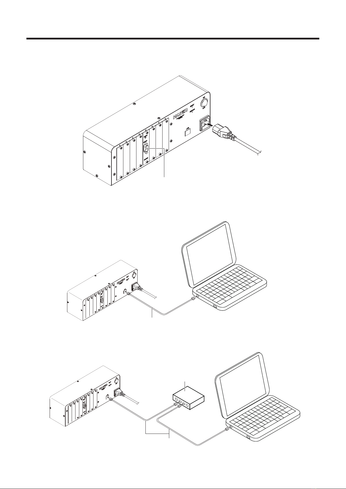
5-2 Connecting the power cord..................................................................................................................... 5
5-3 Connecting the LAN cable ...................................................................................................................... 5
6. INSTALLATION ....................................................................................................................6
6-1 IP Address Setting Application settings................................................................................................ 6
6-1-1 Initially installing the software ........................................................................................................ 6
6-1-2 Updating the software .................................................................................................................... 6
6-1-3 Uninstalling the software................................................................................................................ 6
6-2 Sample Application settings ................................................................................................................... 6
6-2-1 Initially installing the software ........................................................................................................ 6
6-2-2 Updating the software .................................................................................................................... 6
6-2-3 Uninstalling the software................................................................................................................ 6
7. OPERATION .........................................................................................................................7
7-1 Network settings ...................................................................................................................................... 7
7-2 Basic operation ........................................................................................................................................ 8
7-2-1 Startup ........................................................................................................................................... 8
7-2-2 Starting the application .................................................................................................................. 8
7-3 Controllingtheconnectionbox(leoperationsbyHTTPmethods) .................................................. 8
7-4 Support for new models .......................................................................................................................... 9
7-5 LED status ................................................................................................................................................ 9

1
1. PACKING LIST
HAKKOFN-1201(ConnectionBox) ........................... 1
Power cord................................................................... 1
Instruction manual ...................................................... 1
HAKKOFN-1201
(ConnectionBox)
Power cord Instruction manual
SOLDERING STATION
FX-961
Please check to make sure that all items
listed below are included in the package..
2. SPECIFICATIONS
●FN-1201
Powersupply AC100 to 240V 50/60Hz
Power consumption 5W
Outside dimensions 340 (W) x 118 (H) x 102 (D) mm
Weight 2.1kg
*1 This product is protected against electrostatic discharge.
*2 Specications and design are subject to change without notice.
Cautions regarding handling of products with electrostatic protection
Since this product incorporates electrostatic measures such as making plastic parts conductive, grounding
of handpiece and station parts, etc., attention should be given to the following points :
1. Plastic parts such as grips, etc. are conductive, not insulated. When performing repairs, be sure
to take sufcient care during parts replacement and repair so that electrically live parts are not
exposed and that there is no damage to insulation.
2. Be sure to ground the product during use.

2
Inthismanual,itemsrequiringcautionareclassiedinto2categories,“WARNINGS”
and“CAUTIONS”,asdenedbelow.Pleasemakesuretounderstandtheseitemsbefore
reading the main text.
WARNING: Failure to comply with a WARNING may result in serious injury or death.
CAUTION: Failure to comply with a CAUTION may result in injury to the operator, or
damage to the objects involved.
Note: Indicates important steps or items in the procedure being explained.
For safety, be sure to comply with the following cautions.
WARNING
ThisproductisaClassAdeviceandmaycauseelectromagneticinterferenceina
residentialenvironment.Takeappropriateactionsifdifcultiesoccurforauser.
●Donotallowthisproducttobeusedbypersons(includingchildren)without
knowledge or experience without the approval of the administrator.
●Donotallowchildrentoplaywiththisproduct.
●Donotallowchildrentoperformcleaningorusermaintenancewithoutsupervision.
●BeforecheckingtheinsideoftheHAKKOFN-1201orreplacingparts,besureto
disconnectthepowerplug.Failuretodosomayresultinelectricshock.
Failure to comply with the following cautions may result in the risk of electric shock, injury, etc.
CAUTION
●Donotallowthisproducttogetwetoroperatethisproductwithwethands.
●Donotsubjecttheproducttostrongimpact.
●Useonlygenuinereplacementparts.
●Donotmodifythisproduct.
●Alwaysholdthepowerplugwhenpluggingitinorunpluggingit.
●Donotperformanyotheractionswhichseemdangerous.
3. WARNINGS, CAUTIONS AND NOTES

3
4. PART NAMES
4-1 Front View
LED
4-2 Rear View
Connector(LAN)Cover bolts Fuse
Blank panels
Inlet
POWER switch
SELV,non-HazardousEnergyLevel
REBOOT button
RESET button

4
5. INITIAL SETUP
5-1 Installing interface cards
WARNING
Donotallowthisproducttobeusedbypersons(includingchildren)withoutknowledgeor
experience without the approval of the administrator.
1. Remove a blank panel from the back side.
2. Slide the interface card in so that the card edge connector is inserted as far as it will go.
CAUTION
• Turn the power off when changing the interface card.
• If the card is upside-down, the cover bolt cannot be tightened. Also, if the interface card
circuit board is not aligned with the guide rails, the edge connector cannot be inserted.
• When installing an interface card, be sure it is in the correct orientation and be sure to align
the circuit board with the guide rails.

5
5-2 Connecting the power cord
Plug the power cord into the inlet on the back of the connection box.
5-3 Connecting the LAN cable
Connect the connection box and PC with a LAN cable.
LAN cable
LAN cable
・Connecting directly
・Connecting via a router
Router
SELV,non-HazardousEnergyLevel

6
6. INSTALLATION
You must be logged into the computer with Administrator user rights in order to install the software.
6-1 IP Address Setting Application settings
6-1-1 Initiallyinstallingthesoftware
1. Download “FN1201 connection setting utility .zip” le from Document Portal.
2. Choose the folder to install, and decompress the downloaded le at that folder.
6-1-2 Updating the software
1. Download “FN1201 connection setting utility .zip” le from Document Portal.
2. Save the downloaded le in a folder different from the folder where the current software is saved.
Decompress the le, and conrm the version of the software.
3. Overwrite the current software by moving all of the decompressed le to the folder where the
current software is saved.
6-1-3 Uninstalling the software
Delete the folder where the software is installed.
6-2 Sample Application settings
6-2-1 Initiallyinstallingthesoftware
1. Download “FN1201 control application (for FN1010) .zip” le from Document Portal.
2. Choose the folder to install, and decompress the downloaded le at that folder.
6-2-2 Updating the software
1. Download “FN1201 control application (for FN1010) .zip” le from Document Portal.
2. Save the downloaded le in a folder different from the folder where the current software is saved.
Decompress the le, and conrm the version of the software.
3. Overwrite the current software by moving all of the decompressed le to the folder where the
current software is saved.
6-2-3 Uninstalling the software
Delete the folder where the software is installed.

7
7. OPERATION
7-1 Network settings
1. Check that all connections in "5. INITIAL SETUP" have been performed and then switch on the
POWER switch of the connection box and switch on the PC.
2. On the PC, start the IP Address Setting Application.
3. In the IP Address Setting Application, set the internet protocol setting (IPv4 or IPv6) and input the
IP address, subnet mask, default gateway, and NTP server address, and then click [Send].
Initial network settings
Internet protocol IPv4
Network mode Static address
IP address 192.168.1.10
Subnet mask 255.255.255.0
Defaultgateway 0.0.0.0
NTP server address Not set
CAUTION
When the POWER switch is turned on while the reset button pressed, the network setting
isinitialized.
4. Press the Reboot button of the connection box more than three seconds.
CAUTION
Changes to the network settings will not be applied until the Reboot button is pressed
for three seconds.
The settings in Step 3 can also be performed during normal operation. In such case as
well, the changes will be applied when the Reboot button is pressed.
Whenthepowersupplyisturnedoffwithoutpushingtherebootbutton,theconnection
boxmaynotworknormally.
5. Press the Enter key according to instructions of the application, and conrm that the display of the
application becomes " writing completion".

8
7.OPERATION(continued)
7-2 Basic operation
7-2-1 Startup
1. Check that all connections in "5. INITIAL SETUP" have been performed and then switch on the
POWER switch of the connection box and switch on the PC.
2. Check that the blinking interval of the green LED on the connection box has changed from 0.3
seconds to 2 seconds.
7-2-2 Starting the application
1. Start the application.
2. Input the IP address set in "7-1 Network settings", click [Connect], and after checking that the
display has changed to "Connected", click [Start].
3. For information on using the application, refer to the instruction manual included with the
application.
7-3 Controllingtheconnectionbox(leoperationsbyHTTPmethods)
The connection box operates as a le server, and le operations can be used to obtain information and
settings from connected equipment, change equipment settings, and control equipment operations.
Use the HTTP "GET" method to obtain les and the "POST" method to send les.
●Theleswhichcanbehandledbytheconnectionboxareasfollows:
system_inf.txt
(GET only)
Connection box software version number, list of interface cards connected
to the connection box, list of equipment that can be connected to
net_cong.txt Network settings
ifx_stat.txt Status of equipment connected to interface card x
ifx_setting.txt List of settings (set temperature, offsets, etc.) of equipment connected to
interface card x
ifx_sysparam.txt List of system settings (sleep, shutoff, etc.) of equipment connected to
interface card x
ifx_log.txt List of time-linked measurement results (sensor temperature, heater drive
time, etc.) of equipment connected to interface card x
ifx_value.txt
(GET only)
List of measurement results not linked to time (automatic calibration results,
temperature measurement results, etc.) of equipment connected to interface
card x
ifx_prole.txt Prole data of equipment connected to interface card x
ifx_program.txt Program data of equipment connected to interface card x
mac_addr.txt
(GET only)
MAC address and status
time_date.txt Time/date information of connection box
For information on the connection box control commands and each le, refer to the "FN1201 Command
Reference".

9
7-4 Support for new models
In order to add support for a new model to the connection box, it is necessary to install the command
support le for that model.
1. With the connection box connected to the PC, start the Command Support File Installation
Application.
2. Select the le to be installed and click [Send].
3. Press the Reboot button of the connection box more than three seconds.
4. Check that the Command Support File Installation Application shows the installed model and shut
down the application.
CAUTION
Depending on the operating status of the connected equipment, the contents of each
kindoflesenttotheconnectionboxwillnotbeappliedtotheequipmentinsome
cases.
Whether or not the contents have been applied should be checked each time.
Whenthepowersupplyisturnedoffwithoutpushingtherebootbutton,theconnection
boxmaynotworknormally.
7-5 LED status
initializing Green LED blinking at 0.3 seconds interval
Normal operation Green LED blinking at 2 seconds interval
Starting while pressing
the reset button
Red LED lights for 1 second, and changes to LED status of normal
operation (Green LED blinking at 2 seconds interval).
abnormal status Red LED blinking at 0.3 seconds interval
When the LED showed abnormal status, please contact the sales ofce or distributor.

OVERSEAS AFFILIATES
U.S.A.: AMERICAN HAKKO PRODUCTS, INC.
TEL: (661) 294-0090 FAX: (661) 294-0096
Toll Free (800)88-HAKKO
4 2 5 5 6
http://www.hakkousa.com
HONG KONG: HAKKO DEVELOPMENT CO., LTD.
TEL: 2811-5588 FAX: 2590-0217
http://www.hakko.com.hk
E-mail:[email protected]
SINGAPORE: HAKKO PRODUCTS PTE., LTD.
TEL: 6748-2277 FAX: 6744-0033
http://www.hakko.com.sg
E-mail:[email protected]
Please access to the following address for the other Sales affiliates.
http://www.hakko.com
HEAD OFFICE
4-5, Shiokusa 2-chome, Naniwa-ku, Osaka 556-0024 JAPAN
TEL:+81-6-6561-3225 FAX:+81-6-6561-8466
2019.2
MA03033XZ190227
© 2019 HAKKO Corporation. All Rights Reserved.
Company and product names are trademarks or registered trademarks of their respective companies.
Table of contents
Popular Cables And Connectors manuals by other brands

Phanteks
Phanteks REVOLT PH-CBKT-CO BK01 quick start guide

RFS
RFS SPINNER CELLFLEX LCF78-50 installation instructions

Heitronic
Heitronic 21402 Installation and operating instructions

Satson
Satson HDMI-SPL-2201C user manual

INTERTECHNO
INTERTECHNO ITI-10 operating instructions

IDEAL
IDEAL 52 installation instructions

National Instruments
National Instruments NI SHC68 user guide

knapp
knapp DUO 35 ml instruction manual

LEONI
LEONI MegaLine Connect100 Installation instruction

Eagle
Eagle E201CAA product manual

Festo
Festo NEBC-U3G5-ES N-S-U1G4 Series Assembly instructions

Definitive Technology
Definitive Technology SCW-100 owner's manual