6. OPERATION
8. PARTS LIST
7. TROUBLE SHOOTING GUIDE
6. OPERATION
6. OPERATION
●When PASS LED is lit
●When FAIL LED is lit
CAUTION
Moving your feet while on the test plate or not making full contact with your fingers on the pad
can result in an incorrect evaluation. During measurement, remain still on the test plate and
press the pad firmly with 3 fingers.
It indicates that the resistance of the anti-static shoes and the person wearing them is inside
the set range. The resistance range of the shoes at that time is indicated by the LED lamps,
therefore the characteristics of the anti-static shoes can be checked.
It indicates that the resistance of the anti-static shoes and the person wearing them is outside the
set range. Determine the cause and take actions including replacing the anti-static shoes, etc.
※If the measured value is below the lower limit
Example) Soles are worn down.
A piece of metal is stuck in the sole.
※If the measured value is above the upper limit
Example) Thick socks are worn.
Defective shoes, dirty soles, etc.
5. The evaluation result will be displayed.
6. After checking the evaluation result, remove your hand from the pad and step off of the test plate.
* Although the HAKKO FG-460 can be used without being connected to ground, depending
on conditions the ground terminal on the left side of the HAKKO FG-460 (refer to the
"4. PART NAMES" for the terminal location) can be connected to ground.
CAUTION
If you remove your hand from the pad before measurement is completed, a buzzer will sound
3 times and the evaluation result will not be shown. Perform measurement again.
CAUTION
During measurement, the HAKKO FG-460 passes a very small amount of electric current
through a person's body. People who have weak hearts or are using a pacemaker should
not use the HAKKO FG-460.
CAUTION
Measurement of the left foot will start from the center of the pass range or one step below the
center (if the LED range is even).
CAUTION
Measurement of the right foot will start from the range used for measurement of the left foot.
Doing this reduces measurement time because if there are no problems with the shoes the shift
in range will be minimal.
1. Set power switch to ON. The indicator LEDs for the set pass range will light.
2. Put on the anti-static shoes and step on the test plate, being careful not to mix up left
and right shoes.
3. Gently press on the pad of the Hakko FG-460 main unit with three fingers.
4. The left foot will be measured first, followed by the right foot.
● Measurement
Example)If the pass range is 0.1MΩ ≦R ≦ 1000MΩ, measurement will start from
10 MΩ ≦R ≦ 100 MΩ.
CAUTION
Atthetimeofshipmentfromthefactory,
allswitchesaresettoOFF.
(Passrangeis0.1MΩ≤R≤100MΩ.)
Settings such as upper and lower evaluation limits, evaluation buzzer, etc. can be made by setting
the DIP switches on the back of the Hakko FG-460 main unit ON or OFF.
●Setting various settings using DIP switches
DIPswitches
● About evaluation external output
There is an external output terminal on the left side of the HAKKO FG-460 main unit.
The evaluation result can be output from this terminal.
The output circuit is as shown below. The DIP switches can be set to perform output
when evaluation result is PASS or FAIL.
Single wire
Twisted wire
Bar terminal (Without sleeve)
(With sleeve)
AWG
Model
Wire stripped length
Suitable wire
XW4C-03E1-H1
(Omron product)
10 mm
0.2 mm2〜4.0 mm2
0.2 mm2〜2.5 mm2
0.25 mm2〜2.5 mm2
0.25 mm2〜1.5 mm2
24 -12
CAUTION
BesuretosetthepowerswitchtoOFFbeforechangingDIPswitchsettings.
DIP switch number
Setting content
Conductivity evaluation*
Lower evaluation
limit
Upper evaluation
limit
Evaluation
buzzer
Evaluation
external output
Function disabled**
R <0.1 MΩ
R <0.1 MΩ
0.1 MΩ (1×10⁵ Ω)
1 MΩ (1×10⁶ Ω)
10 MΩ (1×10⁷ Ω)
100 MΩ (1×10⁸ Ω)
1000 MΩ (1×10⁹ Ω)
Buzzer ON when PASS
Buzzer ON when FAIL
External output when PASS
External output when FAIL
1
ON
ON
OFF
OFF
2
ON
OFF
OFF
ON
3
ON
OFF
OFF
ON
4
OFF
OFF
ON
ON
7
ON
8
ON
5
OFF
ON
6
OFF
ON
*
If both switch 1 and 2 are set to ON, it is not possible to set the upper evaluation limit.
**If both switch 3 and 4 are set to ON, or if switch 7 or 8 is set to ON, the main unit cannot be used.
DIP switch settings table
1
2
3
HAKKO FG-460
display side
+terminal
− terminal
Photocoupler output
Absolute maximum rating: DC 80V 50mA
DIP switch 6
OFF: External output when evaluation is PASS
ON
: External output when evaluation is FAIL
Evaluation external output terminal block (usage conditions)
※ JIS T 8103 defines different standard values for conductive shoes, general-purpose
anti-static shoes, and special anti-static shoes. The pass range setting corresponding to
each type of shoe can be set by changing the DIP switch settings.
※Use terminals 1 and 2 for external
output.
(Refer to the“4. PART NAMES”
regarding terminal 3.)
・About connecting to terminal block
Example) When connecting wire directly
①Use a wire size corresponding to the suitable wire.
②Strip off 10mm of the insulation from the end of the
wire and twist the wire end together.
③The terminal block has a release hole and a terminal
insertion hole. (See figure at right.) Insert a tool such
as a screwdriver, etc. into the release hole. (a)
④Insert the stripped end of the wire into the terminal
insertion hole. (b)
10mm
CAUTION
If the wire end is pre-soldered, proper connection
will not be possible.
Release hole
Terminal insertion hole
(a)
(b)
※Whenremovingthewire,insertatoolsuchasa
screwdriver,etc.intothereleaseholeandpullout
thewire.
●Product does not operate even
when power is switched on.
●The pass range LEDs do not light.
●The buzzer just sounds 3 times
and no evaluation result is shown.
CHECK
ACTION
CHECK
ACTION
CHECK
ACTION
:
Is the AC adapter and/or connecting cable disconnected?
: Connect it.
: Is the DIP switch settings are correct?
: Refer to the DIP switch settings table and set the
DIP switches ON and OFF.
: Do not release quickly the hand from the pad?
: Keep your fingers on the pad until the evaluation
result of PASS or FAIL is finalized.
※If a problem other than those listed above occurs or if the problem continues even after
performing the solution, contact the dealer from which you purchased the product.
WARNING
Disconnect the AC adapter before service/maintenance procedures. Failure to do so may result in
electric shock.
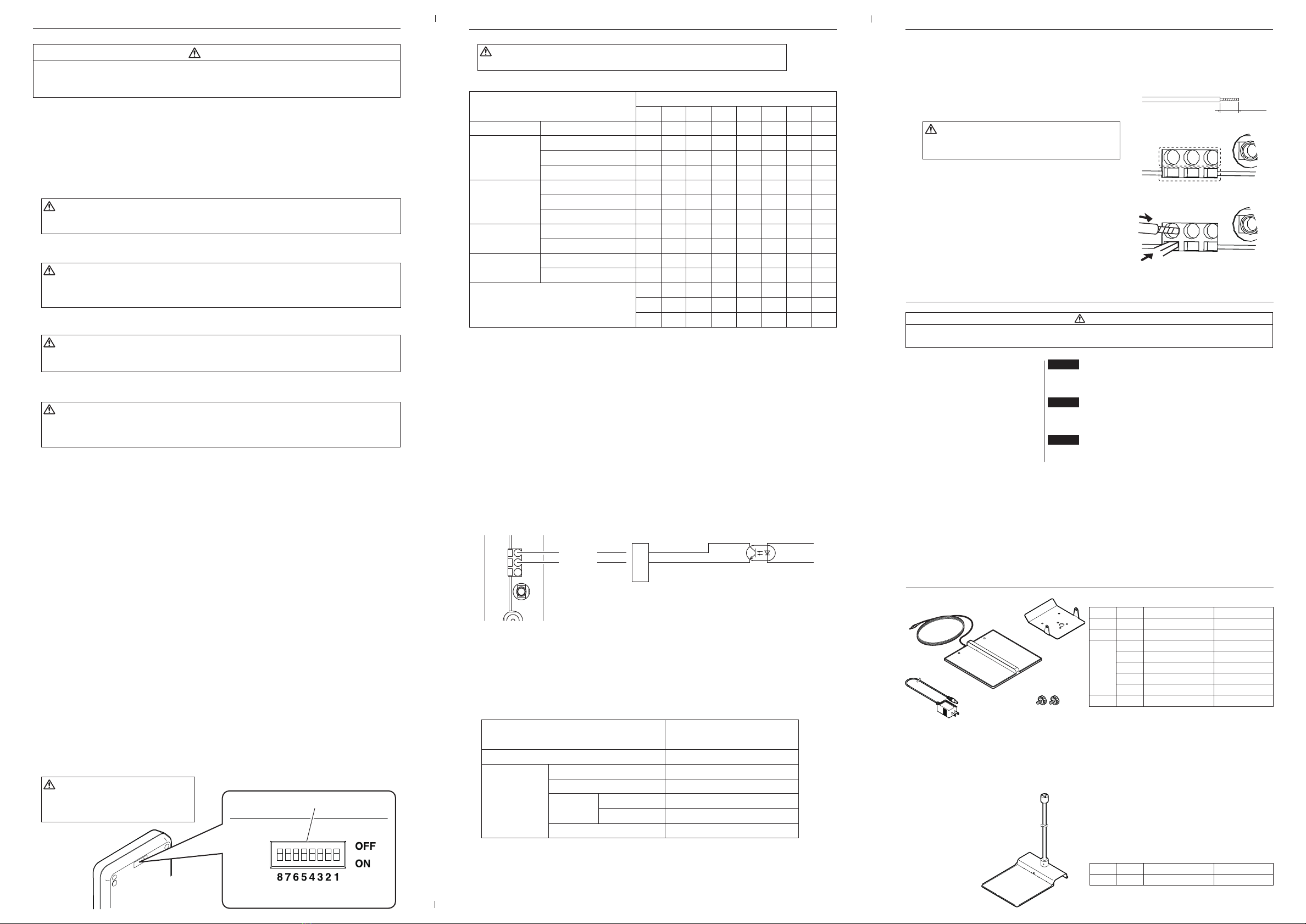
●Optional Parts
Item No.
①
Part No.
C5032
Part Name
Stand
Specifications
Item No.
①
②
③
④
Part No.
B5116
B5117
B5118
B5119
B5120
B5121
B3528
B1991
Part Name
Mounting base
Test plate
AC adapter
AC adapter
AC adapter
AC adapter
AC adapter
Mounting screw
Specifications
with screws
Chinese plug
BS plug CE
European plug CE
Australian plug
2 pcs.
● HAKKO FG-460
①
①
②
③④
Output time: ON for 1 second after evaluation


