Halcro SSP220 User manual

All manuals and user guides at all-guides.com
all-guides.com

1
Contents
ContentsContents
Contents
Introduction
IntroductionIntroduction
Introduction................................
................................................................
...............................................
..............................
............... 3
33
3
Important Safety Information
Important Safety InformationImportant Safety Information
Important Safety Information ..................
....................................
.................. 4
44
4
Symbols ......................................................... 4
Electrical safety............................................. 4
Protection from fluids .................................. 5
Service warnings.......................................... 5
attery disposal............................................ 5
Protection from overheating ...................... 6
Interference warning — US FCC regulations
........................................................................ 6
Additional important safety instructions for
the US ............................................................ 6
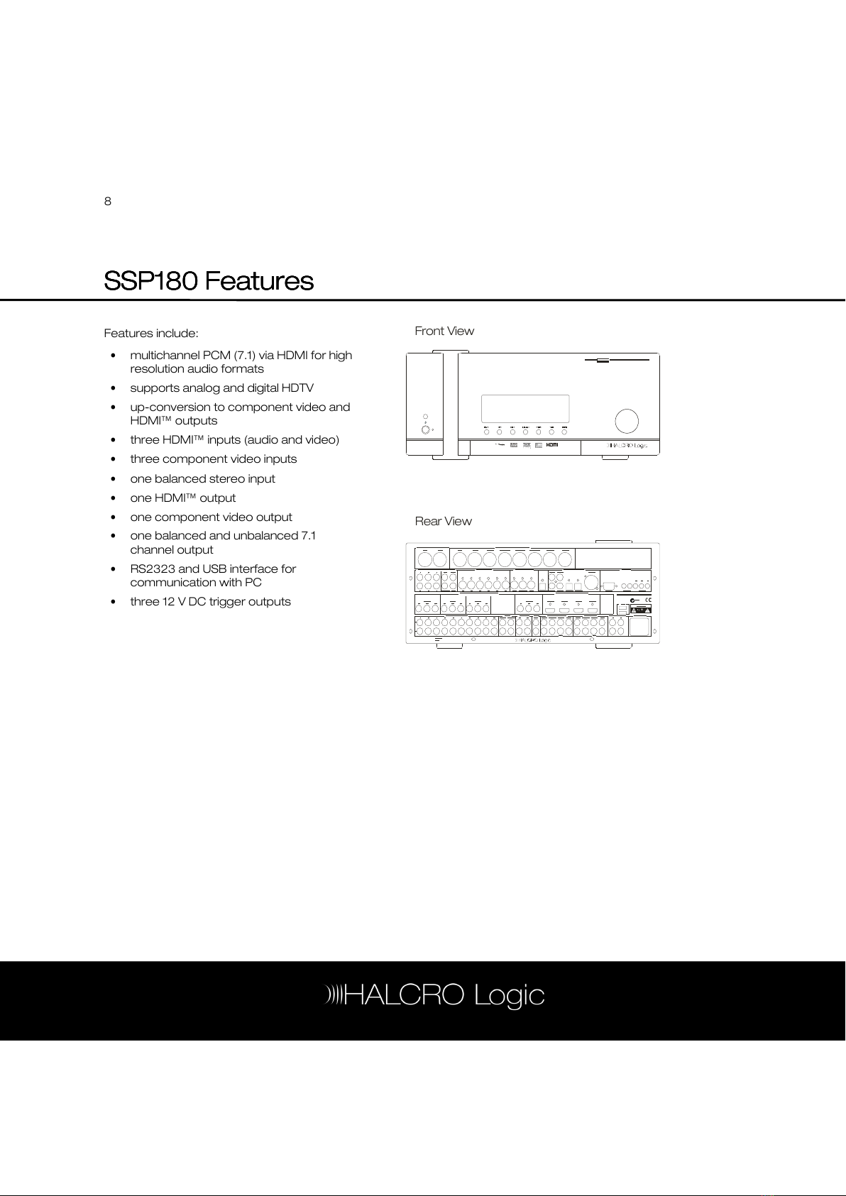
SSP180 Features
SSP180 FeaturesSSP180 Features
SSP180 Features................................
................................................................
......................................
............
...... 8
88
8
SSP220 Features
SSP220 FeaturesSSP220 Features
SSP220 Features ................................
................................................................
.....................................
..........
..... 9
99
9
THX Features
THX FeaturesTHX Features
THX Features................................
................................................................
..........................................
....................
.......... 10
1010
10
Re-equalization............................................10
Timbre matching .........................................10
Adaptive decorrelation................................11
THX Ultra2 .....................................................11
THX Surround EX..........................................11
ASA (Advanced Speaker Array)................12
Installation
InstallationInstallation
Installation ................................
................................................................
...............................................
..............................
............... 13
1313
13
Unpacking ....................................................13
Storing packaging .......................................13
Positioning ....................................................13
Controls and Connections
Controls and ConnectionsControls and Connections
Controls and Connections ....................
........................................
.................... 14
1414
14
Front panel ...................................................15
Rear panel ....................................................16
UTSR1 (Remote Control)
UTSR1 (Remote Control)UTSR1 (Remote Control)
UTSR1 (Remote Control).......................
..............................................
.......................20
2020
20
Accessing the SSP180/220 menus .........21
SSP page 1 ..................................................22
SSP Page 2 ................................................. 24
SSP Page 3 ................................................. 24
Quick Start Guide
Quick Start GuideQuick Start Guide
Quick Start Guide ................................
................................................................
...................................
......
...26
2626
26
Set up flow charts ...................................... 27
Factory default settings............................. 29
Factory default settings ............................ 30
Audio / Video options ................................. 31
Connecting an amplifier(s)........................ 32
Connecting a subwoofer.......................... 33
Connecting a TV monitor.......................... 34
Connecting a DVD player ......................... 35
Connecting a CD player............................ 36
Connecting a VCR ..................................... 37
Viewing the Menus on the OSD
Viewing the Menus on the OSDViewing the Menus on the OSD
Viewing the Menus on the OSD ...........
......................
...........38
3838
38
S
SS
SSP Setup and Operation
SP Setup and OperationSP Setup and Operation
SP Setup and Operation .....................
..........................................
.....................39
3939
39
Starting up................................................... 39
On screen display (OSD)........................... 39
Watching a DVD ......................................... 40
Listening to a CD......................................... 41
Watching a video ........................................ 41
Menu Structure
Menu StructureMenu Structure
Menu Structure ................................
................................................................
......................................
............
......42
4242
42
Speaker Setup
Speaker SetupSpeaker Setup
Speaker Setup................................
................................................................
........................................
................
........43
4343
43
Level setup.................................................. 44
Distance setup ........................................... 44
Size setup.................................................... 45
Aux channel setup ..................................... 46
Autocalibrate — level and distance ......... 49
Audio Setup
Audio SetupAudio Setup
Audio Setup ................................
................................................................
............................................
........................
............ 51
5151
51
Dolby/DTS setup......................................... 51
Preset setup ............................................... 52
Tone controls.............................................. 53
Low frequency effects (LFE).................... 53
Reverb ......................................................... 54
alanced source........................................ 54
alanced routing........................................ 55
All manuals and user guides at all-guides.com

2
Source Setup
Source SetupSource Setup
Source Setup ................................
................................................................
.........................................
..................
......... 56
5656
56
Source ..........................................................57
Title ................................................................57
Digital input.................................................. 58
Preset .......................................................... 58
Analog monitor........................................... 59
To adjust the Analog monitor:.................. 59
Video type................................................... 60
Video Out Mode......................................... 60
Display Setup
Display SetupDisplay Setup
Display Setup ................................
................................................................
..........................................
....................
..........61
6161
61
TV system .................................................... 61
Superimpose ............................................... 61
Temporary display ..................................... 62
Video format ............................................... 62
Distance units ............................................. 63
OSD output ................................................. 64
OSD style..................................................... 64
THX Audio ................................................... 64
ass limiter setup....................................... 65
oundary gain compensation ................. 66
Advanced speaker array ...........................67
Trig
TrigTrig
Trigger Setup
ger Setupger Setup
ger Setup ................................
................................................................
.........................................
..................
......... 68
6868
68
Trigger 1, 2 & 3 ........................................... 68
Polarity ......................................................... 69
Delay .............................................................70
Duration ........................................................70
Care and Maintenance
Care and MaintenanceCare and Maintenance
Care and Maintenance .........................
..................................................
......................... 72
7272
72
Cleaning .......................................................72
Troubleshooting
TroubleshootingTroubleshooting
Troubleshooting................................
................................................................
.....................................
..........
..... 73
7373
73
Service and Warranty Information
Service and Warranty InformationService and Warranty Information
Service and Warranty Information .......
..............
....... 75
7575
75
Overview ......................................................75
Product warranty........................................75
Exclusions to the warranty........................75
Transferability ..............................................76
Warranty verification...................................76
Warranty registration..................................76
If service is required....................................76
Transportation of products ....................... 77
Freight damage claims .............................. 77
If you have moved...................................... 77
Thank you for choosing Halcro! ............... 77
Appendix
Appendix Appendix
Appendix —
——
— Technical Information
Technical Information Technical Information
Technical Information ......
............
...... 78
7878
78
Technical data.............................................78
Mode tables.................................................79
Abbreviations and Units
Abbreviations and UnitsAbbreviations and Units
Abbreviations and Units ........................
................................................
........................ 82
8282
82
Abbreviations.............................................. 82
Units ............................................................. 83
Index
IndexIndex
Index ................................
................................................................
.......................................................
..............................................
....................... 84
8484
84
All manuals and user guides at all-guides.com

3
Introduction
IntroductionIntroduction
Introduction
Congratulations on purchasing the Halcro Logic SSP180 or SSP220 surround sound processor and
preamplifier.
orn from a decade of high-performance two-channel Research and Development that produced
the world’s finest super-high-end amplification systems, comes home theater at the highest level.
Halcro Logic provides unprecedented levels of leading technology, resulting in reliability and Super-
Definition performance.
Halcro Logic is used throughout the world by home theater connoisseurs with a genuine love and
passion for home entertainment at its best.
Please enjoy the Halcro Logic audiovisual experience.
All manuals and user guides at all-guides.com

4
Important Safety Information
Important Safety InformationImportant Safety Information
Important Safety Information
Symbols
SymbolsSymbols
Symbols
The following symbols are used on this
equipment:
The lightning flash with
arrowhead symbol, within an
equilateral triangle, is intended to
alert the user to the presence of
un-insulated ‘hazardous voltage’
that may be of sufficient
magnitude to constitute a risk of
electric shock to a person if
exposed or contacted.
The exclamation point within an
equilateral triangle is intended to
alert the user to the presence of
important operating and
maintenance (servicing)
instructions in the following
pages.
The ‘CE’ symbol indicates
compliance of this device with
the relevant directives of the
European community including
the EMC (Electromagnetic
Compatibility) and LVD (Low
Voltage Directive) standards.
Warning of electrical shock
hazard. Do not open cover
(or back). There are no
user serviceable parts
inside.
Refer servicing to qualified
service personnel.
Electrical safety
Electrical safetyElectrical safety
Electrical safety
WARNING: This product must
always be connected to a
mains socket outlet with a
protective earth connection.
Only use a suitable approved mains cord
complying with European individual country
requirements in the CE Low Voltage Directive
Scheme.
DANG R: Do not
open the cover or
back, or remove any
panels, or try to
modify or repair the
SSP180/220. Opening
the SSP180/220 may
expose you to
dangerous voltages
and will void the
warranty.
WARNING: The Standby/On
button does not disconnect the
unit from the mains power.
To disconnect the unit from the
mains, switch off the unit at the
mains socket outlet and
withdraw the mains plug from
the socket outlet.
All manuals and user guides at all-guides.com

5
The unit should be installed in a position where
the mains plug is easily accessible. Disconnect
the unit from the mains if it is to be left unused
for a long period.
WARNING: No naked flame
sources, such as lighted
candles, should be placed on
the unit.
If naked flame sources tip over
they could result in a fire.
Protection from flui
Protection from fluiProtection from flui
Protection from fluids
dsds
ds
The Halcro Logic SSP180/220 processors are
designed for indoor use only and are not
protected against liquids. They must not be
exposed to dripping or splashing and no
objects filled with liquids, such as vases,
should be placed on them.
If liquid is accidentally spilled on the device,
immediately disconnect the unit from the
mains. Allow sufficient time for complete
evaporation before using the SSP180/220
again. If the liquid is anything other than water,
do not use the device before a qualified
service technician has examined it.
Cleaning may be performed with a slightly
damp cloth that has been wrung until nearly
dry. Refer to the section on Cleaning on
page 72.
WARNING: To reduce the risk
of fire or electric shock, do not
expose this equipment to rain
or moisture.
Do not allow liquids to enter
the unit or contact electrical
terminals.
Service warnings
Service warningsService warnings
Service warnings
All compartments are sealed at the factory. If
the seals are broken, the warranty will be void
and all service costs will be charged to the
owner.
DANG R: Contains no user
serviceable parts. Do not
attempt to open any of the
SSP180/220 compartments
as this may expose you to
dangerous voltages and will
void the warranty.
attery disposal
attery disposalattery disposal
attery disposal
When disposing of used batteries, please
comply with government regulations or
environmental instructions applicable in your
area.
All manuals and user guides at all-guides.com
all-guides.com

6
Protection from overheating
Protection from overheatingProtection from overheating
Protection from overheating
The SSP180/220 generates a certain amount
of heat and requires ventilation. Slots and
ventilation holes are provided for ventilation
purposes, and to ensure reliable operation of
the product. To prevent fire hazards, these
openings must never be blocked or covered.
The SSP180/220 may be stacked on top of a
Halcro Logic MC20/30/50/70 amplifier but
overheating may result if ventilation is
inadequate. Ensure there is at least 4 in
(10 cm) above the uppermost unit for
ventilation.
Follow the precautions listed below. If these
precautions are not followed, overheating or
failure may result. Overheating also shortens
the working life of all components.
•do not block the ventilation holes in the
top or bottom of the unit with any object,
including paper, cloths or curtains
•do not place the unit on a soft surface
such as a rug, or carpet with a thick pile,
into which it could sink
•avoid placing the unit in a built-in
installation place such as a bookcase or a
rack unless you can provide proper
ventilation
•do not operate the unit inside a cabinet
unless it has adequate ventilation (such
as an open back panel)
•allow at least 4 in (10 cm) on all sides of
the unit (except the bottom
WARNING: Do not obstruct
ventilation slots in the chassis.
Additi
AdditiAdditi
Additional important safety
onal important safety onal important safety
onal important safety
instructions for the US
instructions for the USinstructions for the US
instructions for the US
The following instructions should be followed
by customers in the USA in addition to the
safety instructions in the rest of this chapter:
oRead these instructions.
oKeep these instructions.
oHeed all warnings.
oFollow all instructions.
oDo not use this apparatus near water.
oClean only with dry cloth or according
to the cleaning instructions.
oDo not block any ventilation openings.
oInstall in accordance with the
manufacturer’s instructions.
oDo not install near any heat sources
such as radiators, heat registers, stoves, or
other apparatus (including amplifiers) that
produce heat.
oDo not defeat the safety purpose of
the polarized or grounding-type plug.
A polarized plug has two blades, with one
wider than the other. A grounding type
plug has two blades and a third
grounding prong. The wide blade or the
third prong is provided for your safety. If
the provided plug does not fit into your
outlet, consult an electrician for
replacement of the obsolete outlet.
All manuals and user guides at all-guides.com

7
Additional instructions continued:
oProtect the power cord from being
walked on or pinched particularly at
oplugs, convenience receptacles, and the
point where they exit from the apparatus.
oOnly use attachments/accessories
specified by the manufacturer.
oUnplug this apparatus during lightning
storms or when unused for long periods
of time.
oRefer all servicing to qualified service
personnel.
Servicing is required when the apparatus
has been damaged in any way, such as if
the power-supply cord or plug is
damaged, liquid has been spilled, or
objects have fallen into the apparatus, if
the apparatus has been exposed to rain
or moisture, does not operate normally,
or has been dropped.
Interference warning
Interference warning Interference warning
Interference warning —
——
— US
US US
US
FCC r
FCC rFCC r
FCC regulations
egulationsegulations
egulations
This equipment has been tested and found to
comply with the limits for a Class digital
device, pursuant to part 15 of the FCC Rules.
These limits are designed to provide
reasonable protection against harmful
interference in a residential installation. This
equipment generates, uses, and can radiate
radio frequency energy and, if not installed
and used in accordance with the instructions,
may cause harmful interference to radio
communications. However, there is no
guarantee that interference will not occur in a
particular installation.
If this equipment does cause harmful
interference to radio or television reception,
which can be determined by turning the
equipment off and on, the user is encouraged
to try to correct the interference by one or
more of the following measures:
oIncrease the separation between the
equipment and receiver.
oConnect the equipment into an outlet
on a circuit different from that to which the
amplifier is connected.
oConsult the dealer or an experienced
radio/TV technician for help.
Changes or modifications not expressly
approved by Halcro could void the user's
authority to operate the equipment.
All manuals and user guides at all-guides.com

8
SSP180 Features
SSP180 Features SSP180 Features
SSP180 Features
Features include:
•multichannel PCM (7.1) via HDMI for high
resolution audio formats
•supports analog and digital HDTV
•up-conversion to component video and
HDMI™ outputs
•three HDMI™ inputs (audio and video)
•three component video inputs
•one balanced stereo input
•one HDMI™ output
•one component video output
•one balanced and unbalanced 7.1
channel output
•RS2323 and US interface for
communication with PC
•three 12 V DC trigger outputs
Front View
Rear View
All manuals and user guides at all-guides.com

9
SSP220 Features
SSP220 FeaturesSSP220 Features
SSP220 Features
Features include:
•multichannel PCM (7.1) via HDMI for high
resolution audio formats
•supports analog and digital HDTV
•up-conversion to component video and
HDMI™ outputs
•four HDMI™ inputs (audio and video)
•four component video inputs
•one HDMI™ output
•one component video output
•one balanced and unbalanced 7.1
channel output
•one balanced and unbalanced 7.1
channel input
•RS2323 and US interface for
communication with PC
•three 12 V DC trigger outputs
Front View
Rear View
All manuals and user guides at all-guides.com

10
THX Features
THX FeaturesTHX Features
THX Features
The SSP180 and SSP220 include a THX
processing mode to enhance your audio
experience of film soundtracks.
For optimal video performance, THX
recommends bypassing video scaling and
video conversion (i.e. Composite Video In to
Composite Video Out; S-Video In to S-Video
out; Component Video In to Component
Video Out; HDMI In to HDMI Out)
THX is an exclusive set of standards and
technologies established by the world-
renowned film production company, Lucasfilm
Ltd. THX grew from a desire to make your
experience of the film soundtrack, in both
cinemas and in home theaters, as faithful as
possible to the director’s intention.
A film soundtrack is mixed in a special cinema
called a dubbing stage, and is designed to be
played back in large cinemas with similar
equipment and conditions. The soundtrack is
then transferred directly onto Laserdisc, VHS
tape, DVD, and so on. It is not changed for
playback in a small home theater, and
because of this tonal and spatial errors can
occur. THX engineers developed the patented
THX technologies to accurately translate the
sound from the cinema environment into the
home, to correct these errors.
THX cinema processing features include:
•re-equalization
•timbre matching
•adaptive decorrelation
•THX Ultra2
•THX surround EX
•ASA (Advanced Speaker Array)
On this product, when the THX indicator is
on, THX processing mode is automatically
activated (see page 24.
Re
ReRe
Re-
--
-equalization
equalizationequalization
equalization
The tonal balance of a film soundtrack is
excessively bright and harsh when played
back over audio equipment in the home.
Re-equalization restores the correct tonal
balance for listening to the soundtrack in a
small home theater.
Timbre matching
Timbre matchingTimbre matching
Timbre matching
The human ear changes our perception of a
sound depending on the direction the sound
is coming from. In a cinema, there is an array
of surround speakers so the surround
information is all around you. The timbre
matching feature filters the information going
to the surround speakers so that they more
closely match the tonal characteristics of
sound coming from the front speakers in a
cinema. This ensures seamless panning
between the front and surround speakers.
All manuals and user guides at all-guides.com
all-guides.com

11
Adaptive decorrelation
Adaptive decorrelationAdaptive decorrelation
Adaptive decorrelation
In a cinema, a large number of surround
speakers helps create an enveloping surround
sound experience, but in a home theater
there are usually only two speakers. This can
make the surround speakers sound like
headphones that lack spaciousness and
envelopment. The surround sounds also
collapse into the closest speaker as you move
away from the middle seating position.
Adaptive Decorrelation slightly changes one
surround channel’s time and phase
relationship with respect to the other surround
channel. This expands the listening position
and creates — with only two speakers — the
same spacious surround experience as in a
cinema.
THX Ultra2
THX Ultra2THX Ultra2
THX Ultra2
This equipment is THX Ultra2 certified, and as
such it has incorporated all the features above
and has also passed a rigorous series of
quality and performance tests. Only in these
conditions can a product feature the THX Ultra
logo, which is your guarantee that the home
theater products you purchase will give you
superb performance for many years to come.
THX Ultra2 requirements cover every aspect
of the product including pre-amplifier
performance and operation, and hundreds of
other parameters in both the digital and
analog domain.
THX Surround EX
THX Surround EXTHX Surround EX
THX Surround EX
THX Surround EX — Dolby Digital Surround EX
is a joint development of Dolby Laboratories
and the THX Ltd. In a movie theater, film
soundtracks that have been encoded with
Dolby Digital Surround EX technology are able
to reproduce an extra channel which has
been added during the mixing of the program.
This channel, called surround back, places
sounds behind the listener in addition to the
currently available front left, front center, front
right, surround right, surround left and
subwoofer channels. This additional channel
provides the opportunity for more detailed
imaging behind the listener and brings more
depth, spacious ambience and sound
localization than ever before. Movies that
were created using the Dolby Digital Surround
EX technology, when released into the home
consumer market may exhibit wording to that
effect on the packaging. A list of movies
created using this technology can be found
on the Dolby web site at www.dolby.com.
Only receiver and controller products bearing
the THX Surround EX logo, when in the THX
Surround EX mode, faithfully reproduce this
new technology in the home.
This product may also engage the “THX
Surround EX?” mode during the playback of
5.1 channel. ©2004 THX Ltd. All Rights
Reserved 163 material that is not Dolby Digital
Surround EX encoded. In such case the
information delivered to the surround back
channel will be program dependent and may
or may not be very pleasing depending on the
particular soundtrack and the tastes of the
individual listener.
All manuals and user guides at all-guides.com

12
ASA (Advanced Speaker
ASA (Advanced Speaker ASA (Advanced Speaker
ASA (Advanced Speaker
Array)
Array)Array)
Array)
ASA is a proprietary THX technology which
processes the sound fed to two side and two
back surround speakers to provide the
optimal surround sound experience.
When you set up your home theater system
using all eight speaker outputs (left, center,
right, surround right, surround back right,
surround back left, surround left and
subwoofer) placing the two surround back
speakers close together facing the front of the
room, will provide the largest sweet spot. If for
practical reasons you have to place the
surround back speakers apart, you will need
to go the THX Audio Set-up screen (see page
Error! ookmark not defined.
Error! ookmark not defined.Error! ookmark not defined.
Error! ookmark not defined.) and choose the
setting that most closely corresponds to the
speaker spacing, which will re-optimize the
surround sound-field.
ASA is used in three new modes; THX Ultra2
Cinema, THX Music Mode and THX Games
Mode.
All manuals and user guides at all-guides.com

13
Installation
InstallationInstallation
Installation
Ensure you have read the Important Safety
Information on page 4 before installing your
Halcro Logic SSP180/220.
If you require assistance in the unpacking and
installation of your Halcro SSP180/220, please
contact your dealer.
Unpacking
UnpackingUnpacking
Unpacking
Unpack the unit carefully, noting that all
components are present and undamaged.
Your carton should contain the following
items:
•SSP180 or SSP220, as ordered
•mains supply cable (USA and EU)
•three feet (for stacking)
•calibration microphone
•Universal Touch Screen Remote (UTSR1)
with 120 V charger
•docking station
•230 V charger (EU)
•Owner’s Manual CD
•Warranty Card
Storing packaging
Storing packagingStoring packaging
Storing packaging
The packaging is custom-designed to prevent
damage from occurring during transport.
Store the packaging in a dry location.
Positioning
PositioningPositioning
Positioning
We suggest the Halcro Logic SSP180/220 be
positioned on a stable, flat surface. The airflow
to the vents should not be interrupted. Ensure
there is at least four inches (ten centimeters)
clearance around the vents.
Do not install in a location exposed to direct
sunlight or strong artificial light.
Do not install in a location exposed to high
humidity, or where ventilation is poor.
Ensure the mains plug remains easily
accessible.
Do not connect to mains power
until all the connections are
made and checked.
All manuals and user guides at all-guides.com

14
Controls and Connections
Controls and ConnectionsControls and Connections
Controls and Connections
This chapter describes the controls and
connections on the front and rear panels of
the SSP180/220. The numbers on the
diagram below are used throughout the
manual to
reference the SSP180/220 controls and
connections and to assist you in the setup
procedure.
AUDIO OUT 1
4
AUDIO OUT 2 MICROPHONE RS232
US
33
12
5
13 14 15 16
17
6 7 8 9
10
11
1
2
alanced Analo g Audio Inputs
alanced Ana log Audio Outputs
Composite V ideo Inputs & Outputs
Analog Audio Inputs Tape Rec Out Zone External 7.1 Inputs 7.1 Outputs Special Outpu ts
Component Video Inputs & Outputs
HDMI/HDCP Inpu ts & Outputs
S-Video Inputs S-Video Outputs Digital Audio Inputs Control
LeftRigh t Rig htL. Su rroun d L. Su rroun dR. Surro und R. Surro und
3 4 5 6 7 8 9 10 P lay/In R ec /Out 2 2Out Fro nt Su rroun d Cen ter Re ar
1 2 3 4 5 6 Re c Mo n OSD Mo n RS 232 IR In put s Trig gers
3 5 Re c Zon e Co ax 1 Coax 3 AE SE U
Ce nter Ce nterSubw oofer Subw ooferL. R ear L. R earR. Rear R. R ear
4
Su b
6 M on OS D M on Co ax 2 Co ax 4
O ptical 1
Op tical 2
1
In put 1 Inp ut 2 In put 3 In put 4 O utput
Pr Pr Pr Pr PrPb P b P b Pb P bY Y Y Y
Ou tput Input 1 Inp ut 2 In put 3 In put 4
US
2
1
1
Fro nt
Su rroun d
Cen ter R ear
Sub
RISK OF ELECTRIC SHOCK
DO NOT OPEN
Manufactured in the EU
O ptical Out
Serial
Number
SS P220
N9 58
100 -240 VAC
50 -60H z, 1.1A
Left
1
1
L
R
2
2
3
Y
18
A
18
20 21 22 23
24
25
26
27
28
29
30
31
32
33
34
35
36
37
38
45
46
44
43
41
42
40
39
19
Front Panel Controls
Rear Panel Connections
SSP220 Surround Sound Processor
Hi-Def
All manuals and user guides at all-guides.com

15
Front panel
Front panel Front panel
Front panel
1 IR receiver
The infrared sensor for the SSP180/220
Universal Touch Screen Remote (UTSR1)
control unit.
2 Standby/On button
Switches the SSP180/220 on and into
STAND Y mode (see page 39).
3 Standby L D
LED indicating the system is in STAND Y
mode.
4 Display
High quality display showing SSP180/220
operating condition such as selected
input, operating mode and volume. The
SSP220 display is a high quality 7” (18 cm)
digital TFT screen. The SSP180 display is
a high quality blue VFD screen.
5 Mute button
Mutes the SSP180/220 audio output.
6 DIM button
SSP220 — Pressing the DIM button
switches the TFT screen brightness from
bright to dim. Pressing the DIM button
again increases the brightness of the TFT
screen.
SSP180 — Pressing the DIM button
switches the VFD screen brightness from
bright to dim. Pressing the DIM button
again increases the brightness of the VFD
screen.
7 Zone button
Activates Zone control mode to allow
access to the second Zone. (Active in
STAND Y mode but not in SETUP mode.
8 Source button
Selects the Source control option. Once
pressed, turning the volume control
cycles through the available inputs
9 Mode button
Selects the Mode control option. Once
pressed, turning the volume control
cycles through the available processing
modes. (See page 24 and the mode
tables on page 79.
10 THX button
Selects THX processing mode. (Available
modes depend on the input signal type
and speaker configuration.) See page 24.
11 Menu
Selects SETUP mode. The menu is
displayed on the On Screen Display
(OSD). Repeated pressing of the MENU
button allows you to navigate down
through the selected menu page. (A
menu function is selected by rotating the
volume control.) (See page 42.)
All manuals and user guides at all-guides.com
all-guides.com

16
12 Volume control
Controls the volume of the audio output
and can also be used to manually select
menu options, audio/video sources and
mode control.
13 Headphone audio output 1
Stereo output with volume control for the
selected source input.
14 Headphone audio output 2
Stereo output with volume control for the
selected source input.
15 Microphone input socket
Used for auto-calibration of speaker level
and distance. See page 49.
16 RS232 control interface
Used for connecting the SSP180/220 to a
computer or home automation system
17 USB control interface
Used for connecting the SSP180/220 to a
computer or home automation system.
Rear panel
Rear panel Rear panel
Rear panel
18 7.1 balanced audio input (SSP220)
Accepts balanced multi-channel and
stereo inputs from analog audio sources
(SACD or DVD audio player).
18a Stereo balanced audio input (SSP180)
Accepts inputs from balanced audio
outputs of an analog audio source.
19 7.1 balanced audio outputs
Connect to the balanced LINE inputs of
power audio amplifiers. These outputs
feed the same signal as the 7.1 channel
outputs, except that bypassed balanced
audio input can only be heard from these
outputs.
20 Composite video inputs 1 to 6
Accept composite video outputs from
video sources. These inputs 1-6 are
linked to analog audio inputs 1-6.
The received composite video signal is
fed out from the composite video record
(REC), monitor (MON) output, Monitor
with On Screen Display information (Mon
OSD) and Zone output.
21 Composite video record (R C) and
monitor (MON) (with OSD) outputs
Connect the composite REC output to
the composite video input of your
recording device such as a VCR.
(Connect the Mon OSD to a display
device with a composite input (TV). The
video signal with the On Screen Display
will be shown.
You can also use the composite video
Mon OSD output even if no composite
video source is connected. The selected
S-Video signal is down-mixed to this
output and you can use it for monitoring.)
All manuals and user guides at all-guides.com

17
22 Composite video Zone and monitor
(without OSD) outputs
The Zone output can be used, for
example, to send a signal to a TV located
in another room. The monitor output
(Mon) is a high quality composite video
output. The On Screen Display (OSD) is
not displayed on the Mon output.
23 S-Video inputs 1 to 6
Accept S-Video outputs from video
sources. These inputs 1-6 are linked to
analog audio inputs 1-6.
24 S-Video R C output
Connects to the S-video input of a VCR.
25 S-Video monitor output (with OSD)
S-video monitor output, but the OSD is
displayed.
26 S-Video monitor output (without OSD)
Connects to a display with an S-video
input.
27 Optical digital output
Connects to the optical input of your
digital recorder, such as a DAT or a Mini
Disc recorder. The selected digital source
is fed to this output in optical digital
format.
28 Coaxial digital audio inputs 1 to 4
Accept the coaxial digital output from
your source devices. You can freely
associate the digital inputs to any source.
29 Optical digital audio inputs 1 to 2
These connections require optical cables
(Toslink). You can freely associate the optical
inputs to any source (see Source Setup on
page 56).
30 AES/E U balanced digital audio input
This connection requires an XLR cable
and a digital audio source with AES/E U
connector. You can freely associate the
digital inputs to any source.
31 RS232 control interface
Connects the SSP180/220 to a home
automation system or to a PC for
software updates. Contact your dealer
for details.
32 IR inputs
Used for an additional Infrared remote
controller for Zone and main viewing
area. Contact your dealer for details.
33 Remote trigger outputs 1 to 3
Connect the DC trigger inputs of any
audio or other device to the trigger
outputs.
(The trigger output may be activated
when the SSP180/220 is switched out of
STAND Y mode, and immediately turned
off again when the SSP180/220 is
switched into STAND Y mode again. You
can also program the trigger outputs to
be activated under other conditions (see
Trigger Setup on page 68 for further
details).
All manuals and user guides at all-guides.com

18
The trigger outputs deliver 12 V DC. The
maximum total current (for the three
outputs) is 200 mA.
Only connect or disconnect
triggers when the power is off or
the unit is disconnected from
mains power, or the trigger
outputs may be damaged.
CAUTION: Halcro recommends
that trigger cables be a
maximum length of three meters
and to use shielded cable to
prevent possible radio
interference issues.
34 Component video inputs
Accept component video outputs from
video sources.
There are three component video inputs
in the SSP180 and four in the SSP220. All
component video inputs can be
associated to any of the sources in SRC1
to 10 in the Source Setup.
35 Component video outputs
Connect to the component video inputs
of the video display.
36 HDMI™ outputs
Connect to the HDMI™ input of your
video display unit.
(For display systems with DVI inputs a
HDMI™/DVI adaptor is required.)
37 HDMI™ inputs
There are three high-definition multimedia
interface (HDMI™) inputs in the SSP180
and four in the SSP220.
All HDMI™ inputs can be associated to
any of the sources in the Source Setup.
38 USB control interface
Connects the SSP180/220 to a home
automation system or to a PC for
software updates.
Contact your dealer for details.
39 Analog audio inputs 1 to 10
Inputs for analog outputs of source
devices.
(Connections must always be made to
these inputs even when using only digital
sources [such as DVD players] to ensure
there is always a signal at the record
outputs.)
40 Tape input/output
Connectors for all types of tape
recorders, including three-head types,
which allow you to monitor the signal
from the tape at the same time it is being
recorded.
41 Record outputs 1 to 2
These outputs carry the signal from the
currently selected analog stereo source
device (except the source connected to
the tape PLAY input or the 7.1 channel
input).
42 Zone B audio output
A stereo output used to send the Zone
signal from the SSP180/220 to a power
amplifier in another room.
All manuals and user guides at all-guides.com

19
43 7.1 channel unbalanced inputs
Accept audio outputs from any multi-
channel analog source (such as DVD,
SACD, and DVD audio player).
May be used with stereo, mono, 5.1
channel or 7.1 channel sources.
44 7.1 channel unbalanced outputs
Connect to the LINE inputs of audio
power amplifiers. The SU output is
normally fed to the low-level LINE input of
an active subwoofer, or may feed a
passive subwoofer and a separate power
amplifier.
45 Auxiliary channel outputs
Connect to the LINE inputs of power
amplifiers and subwoofers.
Special Output 1 is Aux channel 9 (top)
and Aux Channel 10 (bottom). Special
Output 2 includes two additional
subwoofer line outputs.
46 Power inlet and main switch
All manuals and user guides at all-guides.com
Other manuals for SSP220
1
This manual suits for next models
1
Table of contents
Other Halcro Recording Equipment manuals