4SPS Installation and Maintenance Manual
1 Introduction
1.1 About this Manual
The information in this manual is provided to assist installation and maintenance
personnel in the proper installation, upkeep, and maintenance of the SPS Solar
Power Supply.
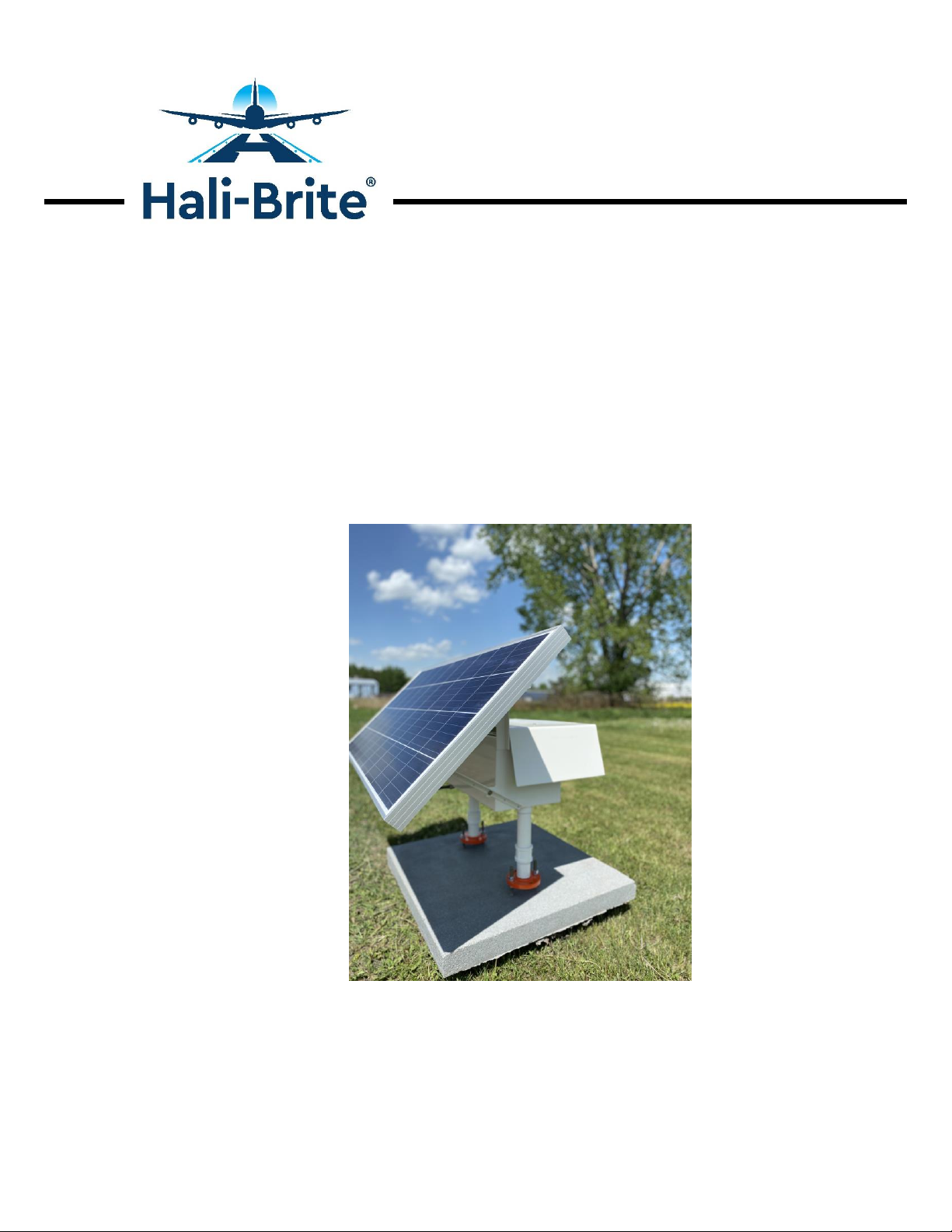
1.2 Model Configurations
SPS-135-2-12: 135 watt panel, 2 batteries, short legs
SPS-135-2-30: 135 watt panel, 2 batteries, tall legs
SPS-135-3-12: 135 watt panel, 3 batteries, short legs
SPS-135-3-30: 135 watt panel, 3 batteries, tall legs
SPS-50-2-12: 50 watt panel, 2 batteries, short legs
1.3 Warranty
Solar Panel: The solar panel warranty is offered by the manufacturer, BP Solar.
Please refer to the warranty materials included with this manual, and contact the
manufacturer directly for warranty claims.
Batteries: The battery warranty is offered by the manufacturer, Concorde Battery
Corporation. Please refer to the warranty materials included with this manual,
and contact the manufacturer directly for warranty claims.
The warranty for the other components of the SPS is offered by Hali-Brite®as
follows:
Hali-Brite®products are guaranteed against mechanical, electrical, and physical
defects (excluding lamps) for a period of one year from the date of installation
or a maximum of two years from the date of shipment and are guaranteed to be
merchantable and fit for the ordinary purposes for which such products are
made. Hali-Brite®will correct by repair or replacement, at its option, equipment
or parts which fail because of mechanical, electrical or physical defects, provided
that the goods have been properly handled and stored prior to installation,
properly installed and properly operated after installation, and provided further
that Buyer gives Hali-Brite®written notice of such defects after delivery of the
goods to Buyer. Hali-Brite®reserves the right to examine goods upon which a
claim is made. Said goods must be presented in the same condition as when the
defect therein was discovered. Hali-Brite®further reserves the right to require the
return of such goods to establish any claim. Hali-Brite’s obligation under this
guarantee is limited to making repair or replacement within a reasonable time
after receipt of such written notice and does not include any other costs such as
the cost of removal of defective part, installation of repaired product, labor or
consequential damages of any kind, the exclusive remedy being to require such