7
7
MODEL EMX-AMP 4K AUDIO EXTRACTOR w/AMPLIFIER
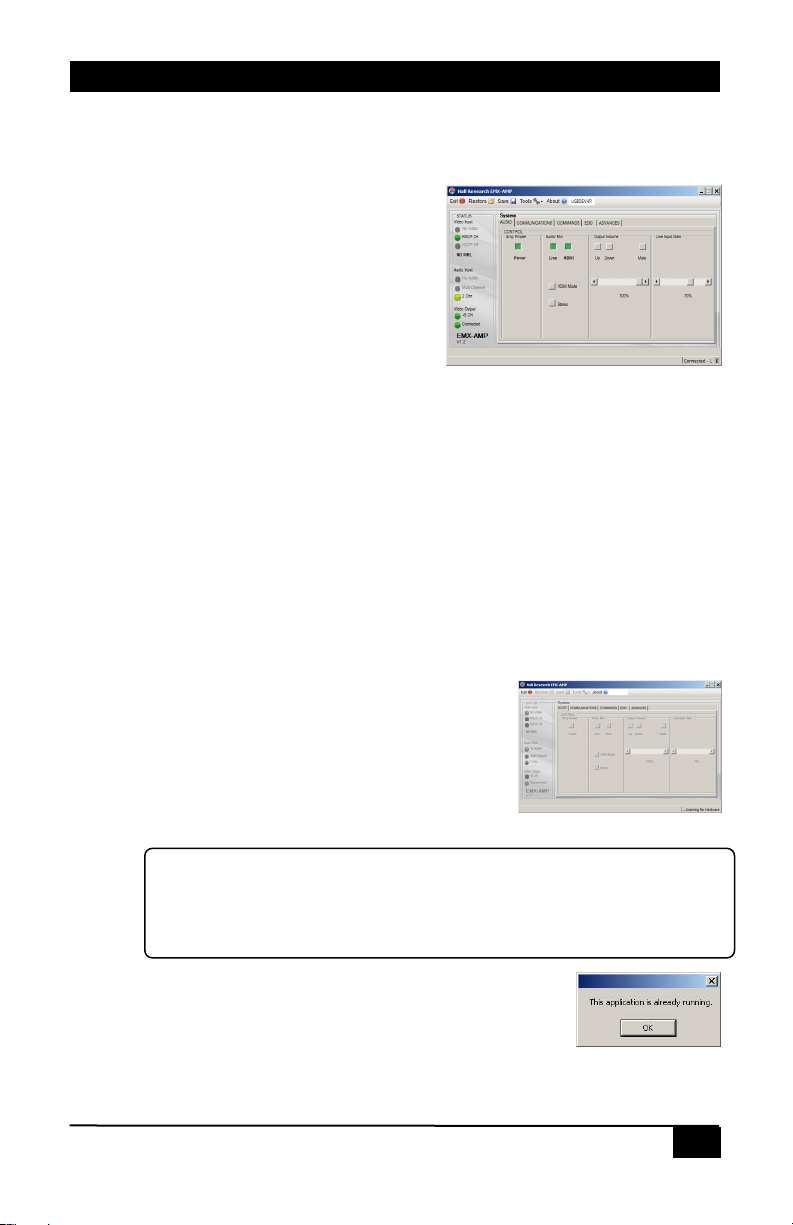
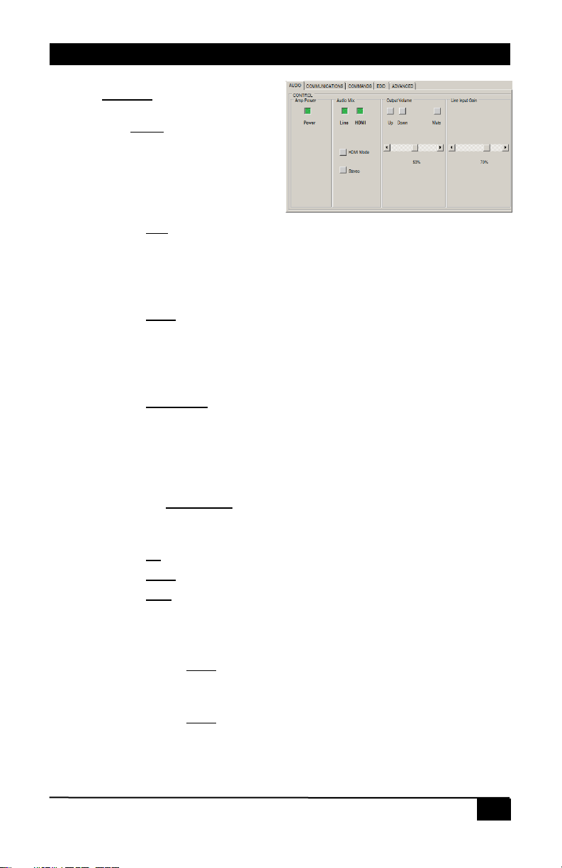
2.7. Audio Tab
Control
Amp Power
The Power control shows both
the device power state as well
as being able to control the ON
or OFF state. Factory default is
OFF.
Audio Mix
The Line control shows both the device LINE Audio state as well as being
able to control the ON or OFF state. Factory default is ON.
•When ON, the 3.5mm LINE IN audio is mixed and output on the
amplifiers speakers and 3.5mm LINE OUT connectors.
•When OFF, the 3.5mm LINE IN audio is not mixed and not output.
The HDMI control shows both the device HDMI Audio state as well as
being able to control the ON or OFF state. Factory default is ON.
•When ON, the HDMI IN audio is mixed and output on the amplifiers
speakers and 3.5mm LINE OUT connectors.
•When OFF, the HDMI IN audio is not mixed and not output.
The HDMI Mode control shows both the device HDMI Mode state as well
as being able to control the HDMI or ARC state. Factory default is HDMI.
•When OFF, the HDMI IN audio is mixed and output on the amplifiers
speakers and 3.5mm LINE OUT connectors.
•When ON, the HDMI OUT ARC audio is mixed and output on the
amplifiers speakers and 3.5mm LINE OUT connectors.
•The Stereo/Mono control shows both the device Stereo/Mono audio
state as well as being able to control the Stereo or Mono state.
Output Volume
The Up control increases the volume by 1% for each click.
The Down control decreases the volume by 1% for each click.
The Mute control shows both the device audio MUTE state as well as being
able to control the MUTE state.
•When ON, the speaker and 3.5mm LINE OUT audio is muted.
•When OFF, the speaker and 3.5mm LINE OUT audio is NOT muted.
The volume Slider control adjusts volume as the user changes the control.
Factory default is 0%.
Line Input Gain
The volume Slider control adjusts the gain of the 3.5mm LINE IN audio as
the user changes the control. Factory default is 70%.
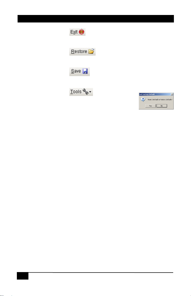
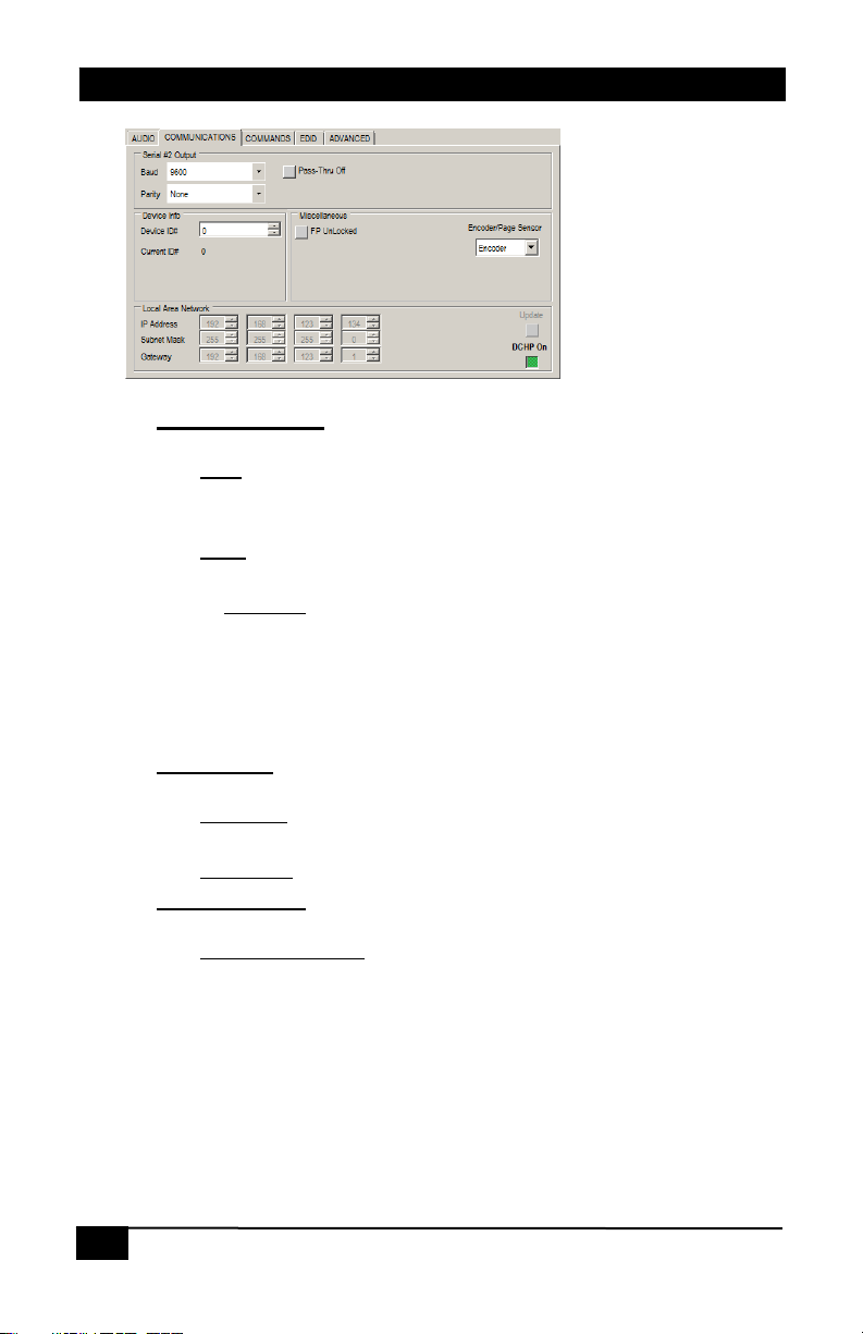
2.8. Communications Tab