Hall Technologies VERSA-4K-S User manual

1
Hall Technologies • 1234 Lakeshore Dr Suite #150 Coppell, TX 75019 • halltechav.com
VERSA-4K User Manual
AV Over IP, 4K Video Over IP, Video Wall, USB 2.0 Over IP + Keyboard &
Mouse, Bidirectional Audio, RS-232 & IR Passthrough, Dynamic Virtual Matrix™
Part Number
Function
VERSA-4K-S
Encoder/Sender
VERSA-4K-R
Decoder/Receiver

2
Table of Contents
1.0 Introduction ............................................................................................... 5
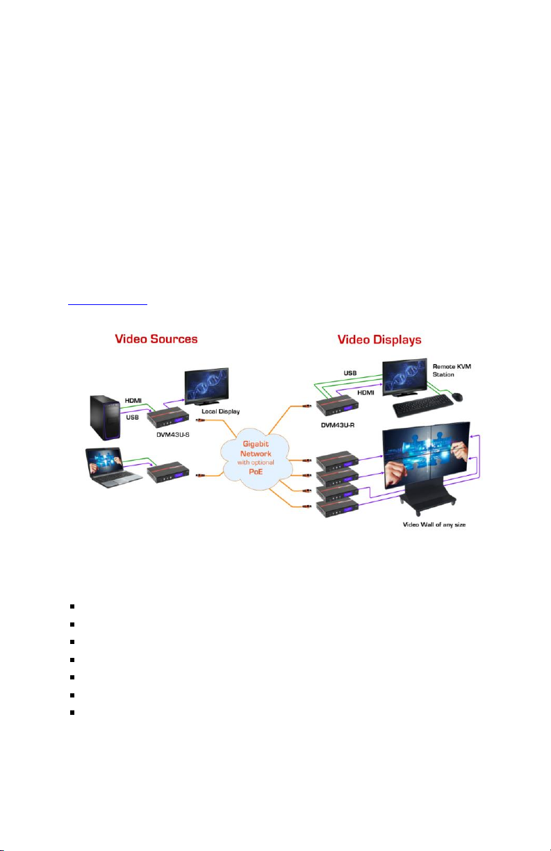
1.1 Applications........................................................................................... 5
2.0 Package Contents...................................................................................... 6
3.0 Input and Outputs ...................................................................................... 7
4.0 Getting Started........................................................................................... 7
5.0 Control Interface........................................................................................ 9
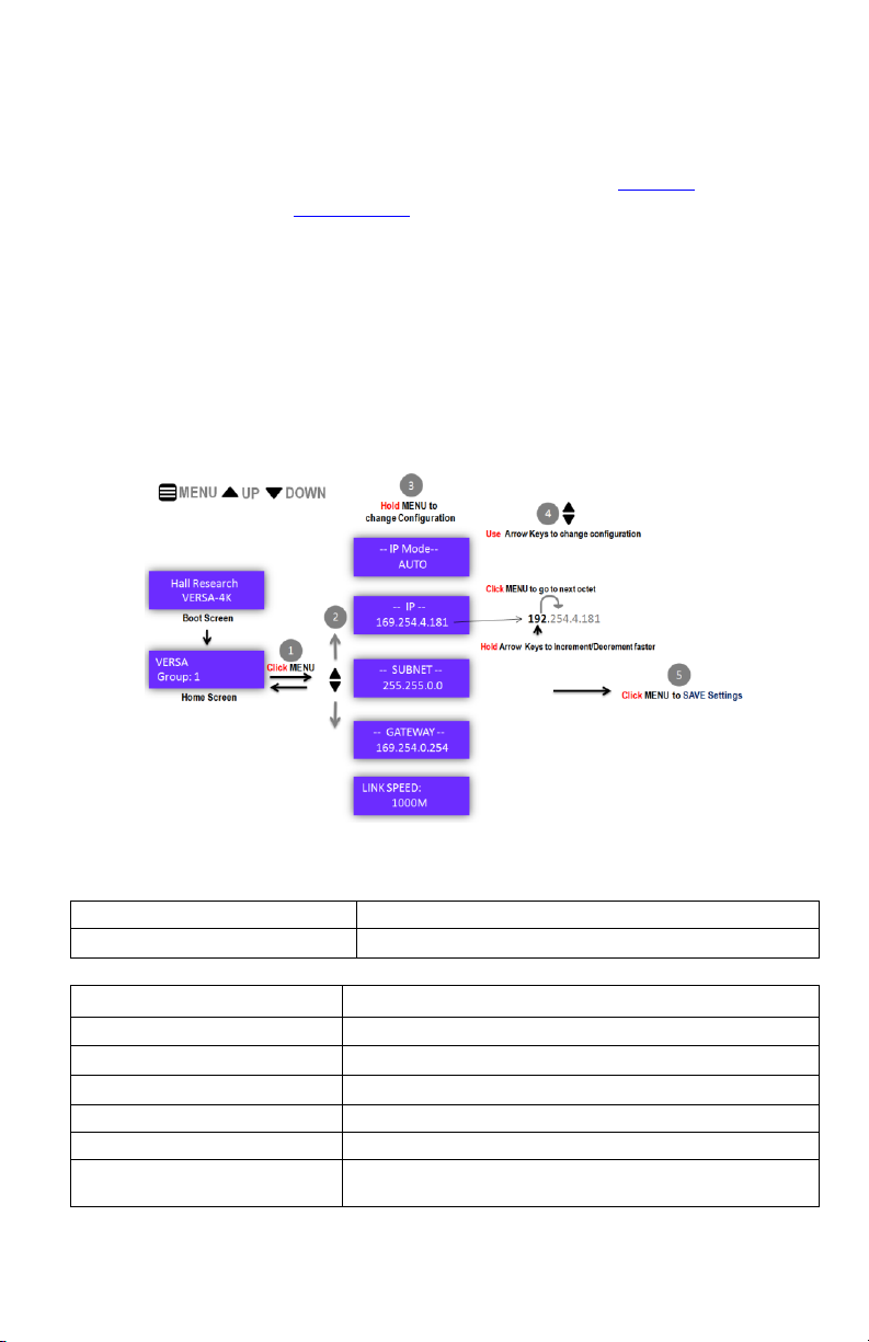
5.1 Front Panel Operation............................................................................ 9
5.2 IR Control ............................................................................................. 10
IR Detectors and Emitters...................................................................... 10
5.3 WEB-GUI............................................................................................... 11
5.4 PC-GUI.................................................................................................. 12
6.0 Working.................................................................................................... 13
6.1 Architecture13
Unicast Mode vs. Multicast Mode......................................................... 13
6.2 General Settings .................................................................................. 14
Device Name.......................................................................................... 14
Group ID................................................................................................. 14
6.3 Auto IP ................................................................................................. 14
6.4 Independent Routing............................................................................ 14
6.5 Video Over IP ....................................................................................... 15
Encoder Settings.................................................................................... 15
EDID Management................................................................................. 15
6.6 Video Scaler......................................................................................... 16
Scaler Settings....................................................................................... 16
6.7 Video Wall............................................................................................ 16
Video Wall Settings................................................................................ 18
Bezel and Gap Compensation ............................................................... 18

3
6.8 OSD...................................................................................................... 19
OSD Settings.......................................................................................... 19
6.9 Audio Over IP ....................................................................................... 19
Audio Modes.......................................................................................... 20
6.10 Keyboard and Mouse Over IP ............................................................ 20
6.11 USB Over IP........................................................................................ 21
USB2.0 Settings..................................................................................... 22
6.12 Serial Over IP ..................................................................................... 22
RS-232 Modes ....................................................................................... 23
6.13 IR Over IP ........................................................................................... 23
IR Modes................................................................................................ 23
6.14 Default Configuration ........................................................................ 24
6.15 Firmware Update ............................................................................... 25
7.0 Specifications .......................................................................................... 26
HDMI Video Resolution Support List ......................................................... 28
VIC Timings ........................................................................................... 28
Other Timings: ....................................................................................... 30
HDMI Audio Format Support List............................................................... 36
USB 2.0 Supported Class List.................................................................... 36
RS-232 Supported Baud rate List............................................................... 36

4
FCC Notice
This device complies with Part 15 of the FCC Rules. Operation is subject to the following
conditions:
1. This device may not cause harmful interference.
2. This device must accept any interference even if it causes undesired operation.
This equipment has been desinged to comply with the limits for a Class A digital device,
pursuant to Part 15 of the FCC Rules. These limits are designed to provide reasonable
protection against harmful interference when the equipment is operated in a
commercial environment. This equipment generates, uses, and can radiate radio
frequency energy, and if it is not installed and used in accordance with the instruction
manual, it may cause harmful interference to radio communications. Operation of this
equipment in a residential area is likely to cause harmful interference, in which case the
user will be required to correct the interference at his own expense.

5
1.0 Introduction
VERSA-4K is a complete AV over IP solution, which can extend 4K video with one
frame latency, USB 2.0, Keyboard, Mouse, IR, RS-232, and Analog Audio over Gigabit
Ethernet Network.
Encoder in the Sender (VERSA-4K-S) uses visually lossless compression, which gives
pixel perfect quality at the remote end. Receiver's inbuilt scaler not only supports
Video Wall up to 16x16, but can also change the Orientation of the Image. VERSA-4K
is one stop scalable solution for your future AV needs, with 10,000 unique channels,
which not only extends video but also extends USB 2.0 devices. With incredible low
latency, VERSA-4K can make its way to Medical Applications, Remote Server
Management, Presentation Rooms, Digital Signage to name but a few.
See Specifications for More details.
Fig 1: Block Diagram
1.1 Applications
Remote PC management
Digital Signage
Interactive Classrooms
Surveillance
Live broadcast
Patient Monitoring
Conference rooms, Auditoriums, Bars and restaurants

6
2.0 Package Contents
Model
Item
Quantity
VERSA-4K-S
VERSA-4K-S
User Manual
Wide Band IR Emitter
Mounting Brackets
Universal Power Supply
1
1
1
1
1
VERSA-4K-R
VERSA-4K-R
User Manual
Wide Band IR Detector
IR Detector (Local Control)
IR Remote Controller
Mounting Brackets
Universal Power Supply
1
1
1
1
1
1
1

7
3.0 Input and Outputs
Fig 2: VERSA-4K-S Front and Rear panel
Fig 3: VERSA-4K-R Front and Rear panel
Front
Panel
FW
USB Mini for Front Panel Firmware update
MENU, UP,
DOWN
User Buttons for front panel operation
RST
Factory Reset
LCD
16x2 Character display for System
Configuration
Rear
Panel
1000BT
RJ45 Jack -- Connects to 1G Ethernet
IR-CTRL
IR Local Control
IR-IN, IR-OUT
IR Detector and IR Emitter connections for
Bidirectional Pass-through
L/R IN, L/R OUT
3.5mm Jack for Analog Line Input and Line
Output
HDMI AUD
HDMI Audio extraction
MIC IN
(Receiver only)
3.5mm Jack for Microphone Analog Input
HDMI OUT
(Sender only)
Video Output
HDMI IN
Video Input
RS-232
RS-232 Phoenix connector for full duplex serial
communication
USB HOST
USB Type B that connects to host PC
USB 1.1, USB2.0
USB Type A for USB peripherals
5V DC
External Power Supply with Locking connector
4.0 Getting Started
1. Use Gigabit Switch with IGMPV2 and Jumbo Frame Support
2. Connect Sender(s) and Receiver(s) to the switch. No DHCP server required,
by default Auto IP is enabled.

8
3. If switch does not support PoE, use external power supply included in the
package
4. Assign unique Group ID to each Sender. The Group ID can be changed from
the Front Panel using UP and DOWN arrow keys or by using IR Remote
Controller (See Front Panel operation for more details)
5. Connect HDMI Source(s) to Sender(s)
6. Connect HDMI Display(s) to Loop out as required
7. Connect HDMI Display(s) to Receiver(s)
8. Connect IR Detector cable to "IR-CTRL" port to use IR Remote Controller
9. If extending bidirectional IR, connect IR Emitter cable to "IR-OUT" port and IR
detector cable to "IR-IN" port of both Sender and Receiver. See IR Over IP for
more details.
10. If Using RS-232, connect RS-232 cable from PC or automation system to the
supplied phoenix connector, and then connect it to the "RS-232" port of
VERSA-4K. See Serial over IP for more details.
11. To control the unit from WEB-GUI or PC-GUI change the IP address of the PC
to Auto IP network
12. Assign Device Name to Sender(s) and Receiver(s) from WEB-GUI or PC-GUI

9
5.0 Control Interface
5.1 Front Panel Operation
VERSA features 16X2 Character LCD with three user buttons: MENU, UP and DOWN
on the front panel, which allows the user to quickly change the Group ID and IP
configuration. By default, Device Name and Group ID on the Home Screen of the LCD,
UP and DOWN arrow keys can be used change the Group ID.
Changing configuration from front panel is a five step process:
1. Press MENU button on Home Screen
2. Use UP and DOWN arrow keys to navigate to a configuration.
3. Hold the MENU button till the configuration starts blinking.
4. Use UP and DOWN arrows keys to see the available Options/Settings.
5. Press MENU again to apply the new configuration.
Fig 4: Front Panel Operation
LCD Notations:
-- [Configuration Name]--
System Configuration
[Status Name]:
System Status
Configuration Name
Options
IP Mode
AUTO, DHCP, STATIC
IP ADD
IP Address
SUBNET
Subnet Mask
GATEWAY
Gateway
BAUD
RS-232 Baud Rate
USB 2.0 (Receiver Only)
Used to the Connect/Disconnect with Sender in the
same group

10
Status Name
Description
MAC ADD
Mac Address of the Device
USB RX IP (Sender Only)
Shows the IP address of the Receiver to which
USB2.0 devices are connected
USB TX IP (Receiver Only)
Shows the IP address of the Sender to which USB2.0
devices are exported
LINK SPEED
Ethernet Link Speed
1000M
1000BaseT (Gigabit Link)
100M
100BaseT
10M
10BaseT
No Link!
When there is no Physical Link or IP
address
5.2 IR Control
IR Remote controller can be used to change the
Group ID of Sender/Receiver. The numeric keypad
on the remote controller can be used to key-In 4-
digit Group ID (0000 to 9999). To use IR Remote
Controller, connect IR Detector Cable (labeled as
"Control") to "IR-CTRL" port on VERSA. See IR
Detectors and Emitters for more information.
Fig 5: IR Remote Controller
IR Detectors and Emitters
IR Detector cable for Passthrough.
Connected to "IR-IN" port of VERSA.
IR Detector cable for Local Control.
Connected to "IR-CTRL" port of VERSA
IR Emitter cable for Passthrough.
Connected to "IR-OUT" port of VERSA

11
5.3 WEB-GUI
Both Sender and Receiver host a WEB Application with intuitive Graphical User
Interface (GUI), which can be accessed using any standard WEB browser. The WEB-
GUI can be used to change various systems setting such as Device Name, Group ID,
USB Control, Audio Control, Video Wall, Independent Routing and Firmware Update
over HTTP etc.
For more advance configurations such as USB Filtering and USB device View use PC-
GUI
Fig 6: VERSA-4K-S WEB-GUI
Fig 7: VERSA-4K-R WEB -GUI

12
5.4 PC-GUI
PC-GUI is used to configure all the advanced settings, such as USB Filtering, OSD,
EDID Management, SOIP, and Bezel and Gap Compensation. With advanced device
finder, PC-GUI gives an advanced top-level management interface to control all the
Senders and Receivers on the network. PC-GUI can provide Video Preview, USB
Device View, Matrix View etc.
Fig 8: PC-GUI

13
6.0 Working
6.1 Architecture
VERSA-4K uses Client-Server architecture, where each function such as Video, Audio,
USB, IR, and RS-232 is considered as a service. VERSA-4K-S (Sender) acts as a server,
and provides services independently under one Group ID. Each VERSA-4K-R
(Receiver) in the network acts a client and receives a service by joining in the group
using Group ID.
A Receiver should have the same Group ID as sender to receive a service. Among all
the services only USB 2.0 is mutually exclusive, means, only one receiver in a group
can exclusively connect to the sender and exports all the USB2.0 attached to it. See
USB over IP for more Details.
Unicast Mode vs. Multicast Mode
Unicast is used in One-to-One Applications, where only one receiver is allowed in a
group. Unicast offers simple and secure ways to extend Video and USB applications
to only one receiver.
Unlike Unicast Mode, Multicast mode is used in One-to-Many Applications, where
multiple receivers are allowed in a group and request services from a sender.
Multicast gives true flexibility to scale the system. Also, enabling Independent
Routing on the receiver allows choose and various services from multiples Sender in
different groups.
Fig 9: Unicast and Multicast Mode

14
6.2 General Settings
Device Name
User can assign custom Device Name to VERSA, which can be used to identify its
Location or Purpose. Device Names are useful for Logical representation of the
system in big installations. Device Names are not linked to IP address, these are only
used as identifiers for the User. For instance, all the Receivers connected to the
projectors in a school can have Room Number as Device Name. By default, the Device
Name is set to "VERSA" for both sender and Receiver.
Group ID
In VERSA's architecture, each service from a Sender is served on Multicast IP. Group
ID is a simpler representation of Multicast IP. Each Sender needs to have a unique
Group ID on the network. A Group ID Ranges from 0000 to 9999, which allows scaling
the system up to 10,000 Senders in one network. A Receiver can receive a service
from a sender by having the same Group ID. In multicast mode multiple Receivers can
join in the same group, and can multiplex various services from Senders in different
groups, which is also called as Independent Routing.
6.3 Auto IP
Auto IP, is also called as Automatic Private IP Addressing (APIPA) is a method where
an IP device on a network selects an unique IP address in the absence of a DHCP
Server. An Auto IP device, such as VERSA holds an IP address in the range of
169.254.x.y in Auto IP Mode, where : x,y can range from 0 to 255.
By default, Auto IP is enabled in VERSA. To access the device WEB-GUI or to control
the device with PC-GUI, the User's PC should be in the following network:
IP Address
169.254.x.y
Where:
x = 0 - 255
y = 0 -255
Subnet
255.255.0.0
6.4 Independent Routing
Independent Routing is featured in the VERSA-4K-R (Receiver), which allows
multiplexing different services from multiple Senders. For example, a Receiver can
receive video form Group-1, Audio from Group-2 and USB from Group-3 as shown
below.

15
Fig 10. Independent Routing
Note: Audio only works when there is an active Video Group.
6.5 Video Over IP
VERSA-4K-S uses visually lossless compression to encode 4K Video. Along with bit
rate and Frame rate adjustments, Sender provides Various Quality modes and Bit
Rate adjustments to minimize the network bandwidth.
Encoder Settings
Bit Rate
Best Effort
VERSA takes complete freedom to deliver best
quality content with less compression. A typical
1080@60 video can take up to 200Mbps bandwidth
10 - 200Mbps
This forces the encoder to compress more to meet
the selected video bandwidth requirement
Frame Rate
0 - 100%
Can be used to minimize the bandwidth by
reducing the number of frames that needs to be
encoded. Low frame rates can be used for Static
Image Videos
Quality Mode
Video Mode
More priority to Frame Rate over Video Quality
Graphic Mode
More priority to Video Quality over Frame Rate.
Some of the frames might be dropped. This mode
is typically used for Static Image Videos.
1 -5
The higher the value, lower the Video quality
Anti-Dither Mode
ON/OFF
Anti-Dither Mode removes the noise in the source
video by averaging them with surrounding pixel
data. Don't enable this if the source video is clean
EDID Management
VERSA-4K Sender can save up to two EDIDs. One of them is Default EDID, which
cannot be modified and other one is a Custom EIDD, which can be updated from
Receiver end. Sender always serves Custom EDID to the source in the absence of
Custom EDID it serves Default EDID.

16
In multicast mode, a receiver in the group can send an EDID Update Request to
replace Custom EIDD with its attached Sink EDID. A Receiver automatically sends an
Update Request when Display is detected, if "Use this EDID" option is enabled. When
multiple receivers send an EDID update request, the last received EDID will be used. In
multicast scenario it is recommended to enabled "Use This EDID" option on only one
receiver.
Fig 11. EDID Management
6.6 Video Scaler
Receiver (VERSA-4K-R) has built-in Video Scaler. The Scaler supports Up-scaling (Low
resolution to High Resolution), Down-Scaling (High Resolution to low resolution) and
Timing Conversion (Interlaced to Progressive and vice versa). See HDMI Video
resolution support list for more information.
The Scaler can be set to "EDID Preferred", which will automatically scale the input
video to the native resolution of the monitor as defined in its EDID. This feature
provides the flexibility to use different kinds of monitors at the Receiver end
regardless of brand and 4K resolution support.
Scaler Settings
Output
Timing
Pass through
Output same resolution as input
Custom Timing
See HDMI Video resolution support list
EDID Preferred
Automatically scales the video to the preferred
EDID timing of the sink
6.7 Video Wall
VERSA receiver has built-in Video Wall support with Bezel and GAP compensation,
Pixel Wise panning, Image Rotation and Mirroring. The Video Wall layout is a
rectangular array of monitors, where the position (x', y') of a monitor on the Wall is
identified with row and column number. The total number of rows indicates Vertical
Monitor Count (Y) and the total number of columns indicates Horizontal Monitor
Count (X).

17
Fig 12. Video Wall Layout
For example, to build a 2x2 (two by two) Video Wall, which has 2 rows and 2 columns.
The Horizontal Monitor Count [X] = 2, and Vertical monitor Count [Y] =2
A total of 4 Receivers are required to build this wall and they can be positioned at:
(0,0) , (0,1) , (1,0), and (1,1)
Each Receiver includes a Video Wall Preview in its WEB-GUI, which helps to visualize
the wall. From the above example to the place a receiver in Top left corner of the
video wall, set the Wall Size = 2x2, and select the position (0,0) as shown below.
Fig13. Video Wall preview in Receiver WEB-GUI

18
Video Wall Settings
Wall Size
[X,Y]
X = [1 to 16] Horizontal Monitor Count
Y = [1 to 16] Vertical Monitor Count
Set [1,1] to disable Video Wall
Position
(x',y')
x' =[0 to 15] Horizontal Position
y' =[0 to 15] Vertical Position
Orientation
Default
Flip Vertical/Horizontal (Mirror Image)
Rotate Clockwise (90/180/270)
Rotate 90 + Flip Vertical
Stretch
Fill/Fit In
Bezel and Gap Compensation
Fig 14. Bezel and Gap Compensation
Scale
Horizontal Scale , Vertical Scale
Shift
Left, Right, Up and Down
In Pixels
Bezel and Gap
Outer Width (OW)
x0.1mm
Video Width (VW)
x0.1mm
Outer Height (OH)
x0.1mm
Video Height (VH)
x0.1mm

19
6.8 OSD
VERSA-4K-R has built-in Hardware On Screen Display (OSD) Controller, which
supports Alpha Blending and transparent settings. A Receiver can display an Image
and Multi color text at any position on the screen. Use PC GUI to upload images and
display text as OSD.
OSD Settings
Position
Offset in pixels
[X,Y]
OSB predefined Presets
Top-Left/Top -Right
Bottom-Left/Bottom-Right
Top/Bottom/Left/Right
Text
Color
RGB: [x,y,z]
Character Count
128
Text Pixel Size
[1 to 100]
Text Align
Center/Left
OSD Alpha Blend (31 is no
transparency)
[1 to 31]
OSD Background
Mask ON/OFF
Timer (In Seconds)
Always ON/ [0 to 100]
Image
Size
640x480
Type
JPEG /PNG 32bpp
6.9 Audio Over IP
VERSA Supports up to 7.1ch HDMI Audio (See HDMI Audio Format Support List for
more details). The Sender also supports HDMI audio embedding from LIN IN, which is
used for VGA sources. Bidirectional audio pass-through is only available in Unicast
Mode, which make it ideal solution for Remote PC extension.
Fig 15. Bidirectional Audio Pass-through
In multicast Mode, Sender supports 3 Input Modes to select an audio source between
HDMI Audio and LIN IN Audio. The selected audio source is embedded into the video
and multicast to all the Receivers in the group. Also, Receiver supports 3 Output
Modes to route audio between LINE OUT and HDMI OUT. See Audio Modes for more
details.
Note:

20
1. While using Independent Routing, receiver must be a part of a working video
group to output the audio.
2. Bidirectional Audio Pass-through is only supported in Unicast Mode and
when LINE IN is selected.
Fig 16. Audio Modes
Audio Modes
Input Mode
(Sender only)
Auto
Auto Selects LINE IN when Video Input is
DVI or when LINE IN hot plug is detected
Auto 1
Auto Selects LINE IN when LINE IN hot
plug is detected irrespective of Video Input
Auto 2
Always uses HDMI audio when Video Input
is not DVI.
Also, Auto selects LINE IN when Video
Input is DVI.
Output Mode
(Receiver only)
Dual Output
Output Audio on both HDMI and LINE OUT
HDMI Only
Only output audio on HDMI
Line Out Only
Only output audio on LINE OUT
6.10 Keyboard and Mouse Over IP
Keyboard and mouse connected at the receiver end operates differently compared to
other USB2.0 devices. To have instant accesses to the PC, both keyboard and mouse
are always emulated by the Sender and only key and mouse parameters are received
from each Receiver. As result, no explicit connection or driver installation is needed.
In multicast mode, a PC can be controlled using mouse and keyboard from any
receiver in the group. Each receiver has dedicated keyboard and mouse ports to use
feature.
This manual suits for next models
1
Table of contents
Other Hall Technologies Media Converter manuals
Popular Media Converter manuals by other brands

Loop Telecom
Loop Telecom Loop-V4300 user manual

MDS Power
MDS Power VTCi320 Installation and operation manual

YASKAWA
YASKAWA CDMR-Z II instructions

IMC Networks
IMC Networks IE-MediaChassis/1 Specifications

PCB Piezotronics
PCB Piezotronics 422E5 Series Installation and operating manual

Idis
Idis DA-MC1101 Operation manual