HALLER + ERNE BG02-EIP User manual

HALLER + ERNE GMBH
Manual BG02-EIP
Ethernet/IP Gateway for System 300/310
Document revision 1.3 –2008-06-04
for BG02-EIP firmware V1.4

Version history
I
Version history
V1.0
2008-04-08
HE
created
V1.1
2008-05-19
HE
Updated description for ControlLogix setup
V1.2
2008-05-21
HE
Added changes for firmware V1.3
V1.4
2008-06-04
HE
Added changes for firmware V1.4, added some diagnostic details, added
firmware update procedure, fixed some typos

Table of content
II
Table of content
1 Overview.......................................................................................................................................... 1
1.1 General information................................................................................................................ 1
1.2 Technical data.......................................................................................................................... 1
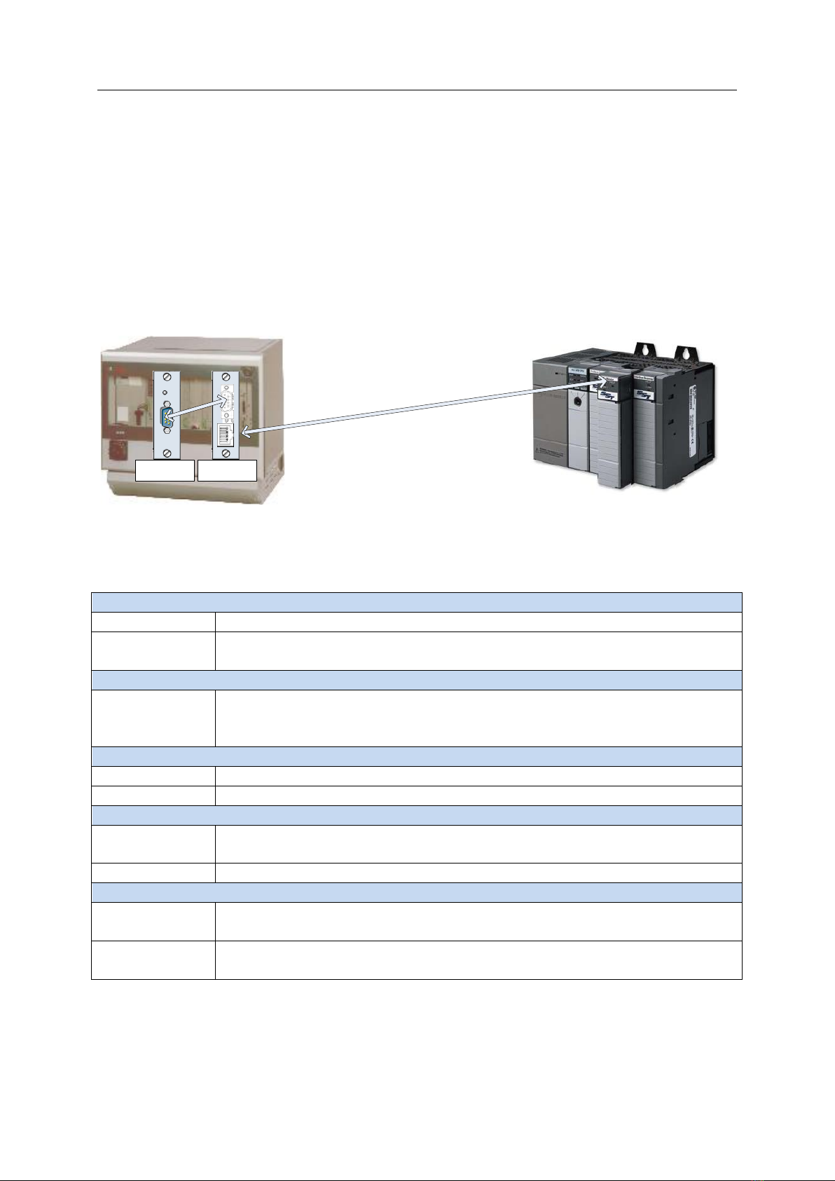
1.3 Mounting instructions............................................................................................................. 2
1.3.1 Inserting into the tightening system ............................................................................... 2
1.3.2 Connecting with the SMpdp/IMpdp module .................................................................. 2
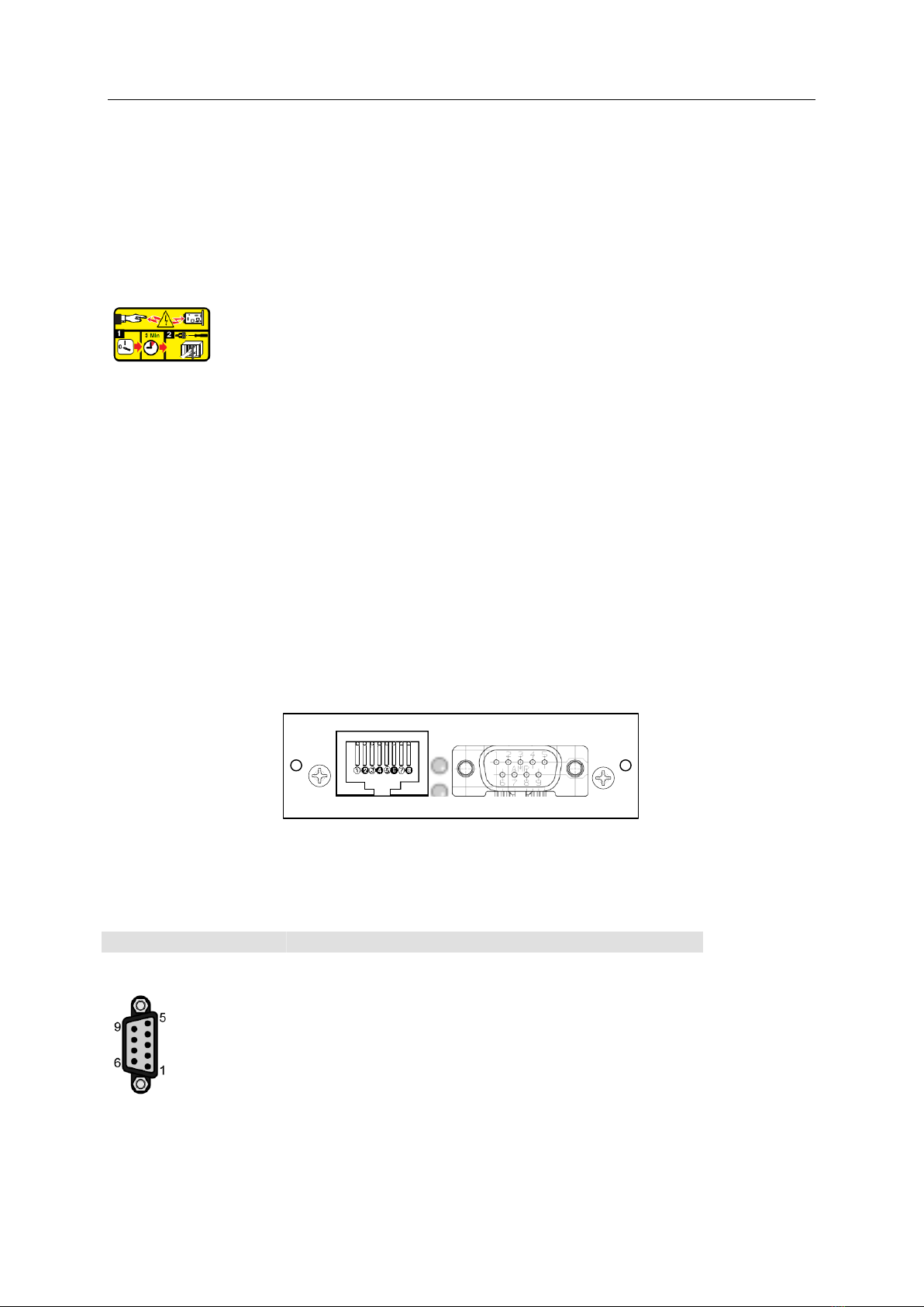
1.4 Interfaces................................................................................................................................. 2
1.4.1 X1 IMpdp/SMpdp ............................................................................................................ 2
1.4.2 X2 Ethernet...................................................................................................................... 3
1.4.3 Diagnostic LED’s A/B........................................................................................................ 3
2 Configuration................................................................................................................................... 3
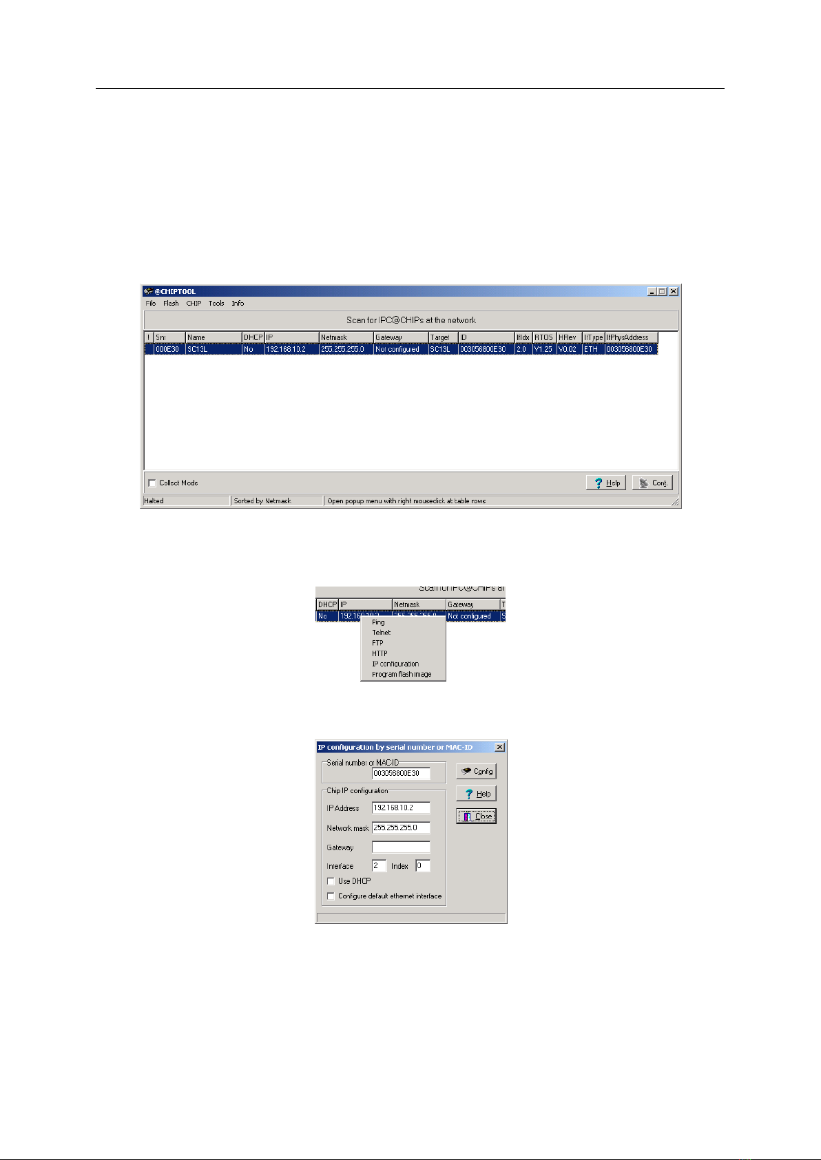
2.1 BG02-EIP configuration ........................................................................................................... 3
2.1.1 BG02-EIP factory defaults................................................................................................ 3
2.1.2 Changing settings ............................................................................................................ 4
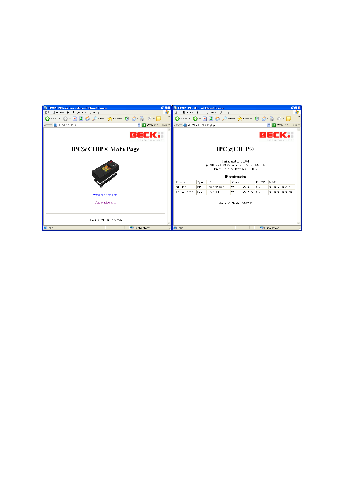
2.1.3 Web browser access........................................................................................................ 5
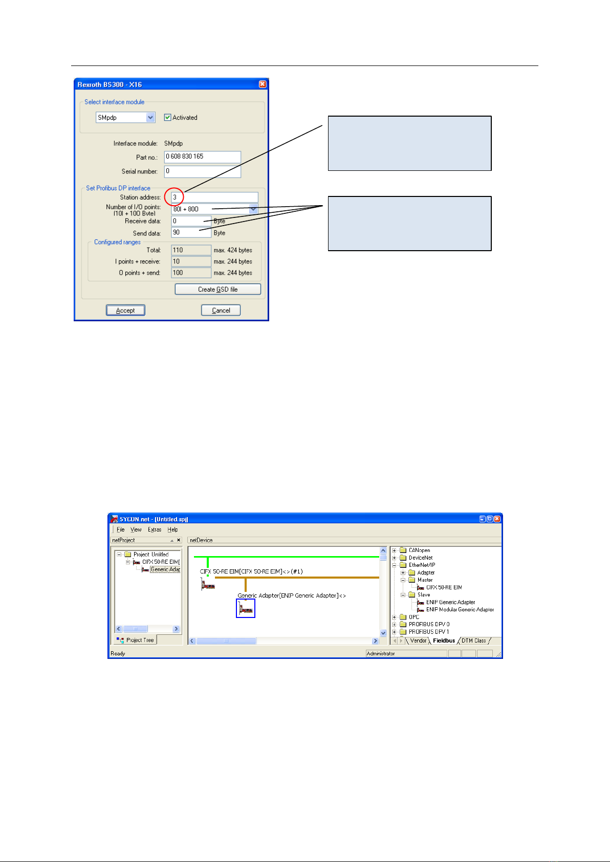
2.2 Configuring the tightening system .......................................................................................... 5
2.3 Ethernet/IP Scanner Configuration ......................................................................................... 6
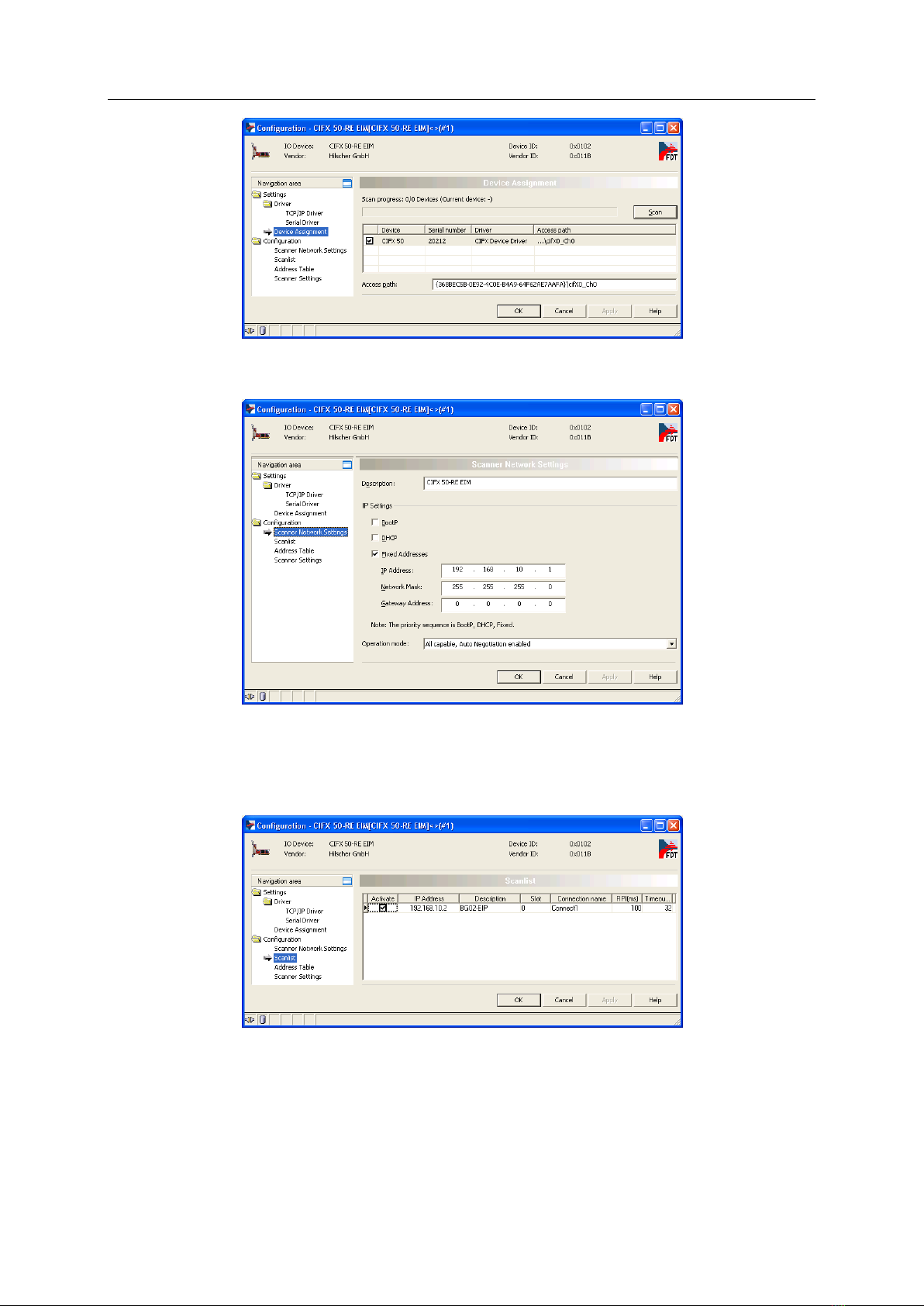
2.3.1 Configuration with Hilscher Sycon.NET........................................................................... 6
2.3.2 Configuration with ControlLogix ..................................................................................... 9
3 EtherNet/IP adapter functionality................................................................................................. 10
3.1 Message Server ..................................................................................................................... 10
3.2 Process Data Mapping........................................................................................................... 10
3.2.1 Input data (PLC BG02 KE)..................................................................................... 11
3.2.2 Output data (KE BG02 PLC).................................................................................. 11
3.3 Behaviour on errors............................................................................................................... 13
3.3.1 Ethernet/IP errors ......................................................................................................... 13
3.3.2 Profibus errors............................................................................................................... 13
4 Reference ...................................................................................................................................... 14
4.1 Operation details and timing................................................................................................. 14
4.2 EtherNet/IP CIP Object Classes ............................................................................................. 15
4.2.1 Identity Object Class (Class code 0x01)......................................................................... 15
4.2.2 Message Router Object Class (Class code 0x02) ........................................................... 16
4.2.3 Assembly Object Class (Class code 0x04) ...................................................................... 16
4.2.4 Connection Manager Object Class (Class code 0x06).................................................... 16
4.2.5 TCP/IP Object Class (Class code 0xF5) ........................................................................... 16
4.2.6 Ethernet Link Object Class (Class code 0xF6) ................................................................ 16
4.3 Firmware update ................................................................................................................... 16

Overview
1
1Overview
1.1 General information
The BG02-EIP module provides EtherNet/IP connectivity for the System 300/310 tightening
controllers. It acts as a gateway between the EtherNet/IP master (scanner) and a Profibus Interface
card plugged into the System 300/310. The following picture shows the general system structure:
PLC
SE/KE
EtherNet/IP
SMpdp BG02
1.2 Technical data
Ethernet-Interface
Ethernet
Ethernet 802.3 10/100MBit interface, automatic 10/100MBit detection
EtherNet/IP
EtherNet/IP adapter device
Minimal I/O update rate 20ms
IMpdp/SMpdp-Interface for SE/KE tightening system
IMpdp/SMpdp
Compatible to System 300/310 SMpdp and CS351 IMpdp
Automatic detetion of KE/SE’s PLC-Configuration data mapping
Up to 240 bytes I/O
Electrical characteristics
Power supply
24VDC, provided by SE/KE over internal slot connector
Power req.
ca. 2W
Environment
Temperatur
Allowed ambient temperature in operation 0°C bis 55°C
Allowed ambient temperature for storage -20°C bis +70°C
Humidity
Allowed humidity 20%-70%
Mechanical
Dimensions
(W*H*D)
24 * 81 * 207 mm3
Connectors
DSUB9 female for IMpdp/SMpdp connection (by cable)
RJ45 for Ethernet

Overview
2
1.3 Mounting instructions
1.3.1 Inserting into the tightening system
The module is inserted into any free interface slot of the system component KE3xx or SE3xx. The
module only uses the internal system connection for power supply, there are no other internal
connections and therefore no special configuration in BS300 required.
Before inserting the interface module, the BT300 card rack must have been voltage-
free for at least 3 min.
Please take care that the interface module is completely inserted. The front knurled bolts must be
tightened and fastened securely. Please take care that the front blind fits closely to BT300.
The module's power supply ensues directly via the control unit. Only the data interface is accessable
from the exterior.
1.3.2 Connecting with the SMpdp/IMpdp module
Use the supplied cable to connect the BG02-EIP to the SMpdp module. If the cable is too short, us a
standard Profibus-type cable to connect BG02-EIP X1 with SMpdp.
1.4 Interfaces
The following picture shows the available front panel interface connectors:
X2
A B
X1
BG02-EIP
1.4.1 X1 IMpdp/SMpdp
Connector X1 is a 9-pin DSUB type socket (female). The pinout is as follows:
X2 (male)
Pin
Signal
io
Beschreibung/Funktion
1
-
-
Not connected
2
-
-
Not connected
3
TxRx+
io
RS485 positive signal line
4
-
-
Not connected
5
GND
-
Reference ground for pins 3 and 8
6
VP
o
+5V terminator supply
7
-
-
Not connected
8
TxRx-
io
RS485 negative signal line
9
-
-
Not connected

Configuration
3
1.4.2 X2 Ethernet
Connector X2 is a standard RJ45 Ethernet plug. Only one LED is available for indicating traffic (green
LED).
The connectors pinout is according to the 100Base-TX standard.
1.4.3 Diagnostic LED’s A/B
There are two LED’s for visual indication of the operation mode of the BG02_EIP interface card:
-LED A: Ethernet/IP connectivity: This LED indicates the operating state of the Ethernet/IP
interface. The following states are shown:
oGreen blinking: Ethernet/IP master connected and data exchange running
oGreen/Red blinking: Ethernet/IP master connected, but data exchange not active.
Either the master is not yet configured or it is not configured correctly (wrong
assembly instance or attribute size defined for data exchange).
oRed blinking: no Ethernet/IP master connected.
-LED B: SMpdp/IMpdp connectivity: This LED indicates the operating state of the SMpdp
interface:
oGreen blinking: Everything ok, data exchange running
oGreen/Red blinking: SMpdp physical connection detected, but no data exchange
running. This indicates a problem with the SMpdp configuration.
oRed blinking: no communication with the SMpdp module possible. Check cable and
station address setting inside the BS300 software (station address of SMpdp must be
set to 3).
After switching on the power supply, the LED’s will do a “lamp test” after a approx 4-5 seconds
bootup delay. For a duration of 2 seconds both LED’s should then run off – red –green –orange
cycles.
2Configuration
2.1 BG02-EIP configuration
2.1.1 BG02-EIP factory defaults
By default, the BG02-EIP is shipped with the Network configuration set to use DHCP for dynamic
address assignment (according to the ODVA recommendation for Ethernet/IP adapters). If no DHCP
server is found, a link local address from the 169.254.x.y network is used.

Configuration
4
2.1.2 Changing settings
To modify network settings, use the supplied “ChipTool” software. The software can be installed by
running CHIPTOOL_INSTALL_V5.10.0.1.EXE.
After the software is installed, it can be started from the start menu entry “@ChipTool”. The
software immediately starts to scan the network for available BG02’s and shows each BG02 found in
a list (see the following screenshot):
Note that the serial number as well as the current network settings are shown. To change network
settings right click on the line where the BG02 is show and select IP configuration:
This will show the following dialog, where you can edit the network settings:
After everything is set up, press the “Config” button to transmit changed settings to the BG02.

Configuration
5
2.1.3 Web browser access
Additionally (if the IP-address of the BG02 is known) you can use a standard web browser to access
the BG02-EIP web server (use http://ip-address-of-BG02/ to access the default page). After clicking
the link “Chip configuration” a page showing the systems configuration (version and serial number
information as well as IP configuration):
2.2 Configuring the tightening system
In general, the tightening system requires a profibus slave card (SMpdp) to communicate with the
BG02-EIP. So the configuration of the tightening system is actually configuring the SMpdp card
correctly:
-Configure the SMpdp card hardware
-Configure PLC mapping table
-(optional) configure Profibus data output, profibus ID-Code and ID-Code device
The tightening system is configured by using the BS300 software. To setup the SMpdp hardware go
to System Tightening channel configuration (for a SMpdp inside a SE) or System KE
configuration (for a SMpdp inside a KE). Then make sure to setup the SMpdp as follows:

Configuration
6
Then continue to configure the PLC mapping table and Profibus data input/output as needed. The
BG02 does not require any other settings inside the SE/KE.
2.3 Ethernet/IP Scanner Configuration
2.3.1 Configuration with Hilscher Sycon.NET
The following screenshots show how to setup a CIFx50-board to communicate with the BG02.
Start by adding the master (scanner) and slave (BG02-EIP adapter) devices. Note that the BG02 must
be added as “ENIP generic adapter):
Then configure the master by double-clicking the CIFx 50 icon. Note that the slaves IP address is
configured in the scan list of the master, therefore entering the IP address of the slave is done in the
masters settings (!). Start by assigning a physical device to the driver (place a checkmark in the line
“CIFX 50”):
Important: The station address
must be set to 3
Setup as required by your
application

Configuration
7
Now click the “Scanner Network settings” inside the ”Configuration” folder to setup the scanner:
If everything is set up, go on to the “Scanlist” settings. This is where you can setup which IP addresses
the scanner should actually scan (i. e. the IP addresses). You should modify the IP address so it
matches the actual IP address of the BG02:
Press OK to finish the masters configuration, then double-click the “generic adapter” icon to
configure the BG02-EIP settings. First set the keying parameters (you may also change the name in
the “General” config):

Configuration
8
The next step is to setup the connection parameters. Make sure to set all parameters exactly as show
in the following screenshot:
The last step is to define the process data access paths. The BG02-EIP provides all process data in
assembly instances. Please setup everything exactly as shown in the screenshot:

Configuration
9
2.3.2 Configuration with ControlLogix
NOTE: This information is copied from the Beck manuals.
To run the BG02-EIP in a ControlLogix environment it is necessary to configure the module under the
I/O Configuration section in a RSLogix 5000 project. Please refer to the RSLogix 5000 user docs on
how to do this. The next illustrations just show the basic settings.
First a Generic Ethernet Module must be selected:
The next figure shows the module properties. Please make sure that the connection parameters will
match exactly the definitions as outlined above. The only exceptions are the Assembly Instances for
Input and Status Input (if configured). The ControlLogix does not strip off the 32 bit header in front of
the data sent by the module. This means that 4 more bytes have to be configured than needed. The
user data can be found in word two of the corresponding input tag.
NOTE: depending on the ControlLogix version a different value for the “Configuration” parameters
are required: Please try empty values for both “assembly instance” and “size” or use “100” for
“assembly instance” and “0” for “size”.
To finish the Connection Parameter settings a Requested Packet Interval (RPI) has to be chosen. The
minimum allowed interval is 20ms!

EtherNet/IP adapter functionality
10
3EtherNet/IP adapter functionality
3.1 Message Server
The EtherNet/IP stack in the BG02-EIP provides EtherNet/IP adapter functionality. No outbound
connection capability or outbound UCMM client services are implemented. The following “Level 2”
adapter class functionality is provided:
-UCMM Message Server
-Class 3 Message Server for up to 32 class 3 connections (limit configurable)
-Class 1 Message Server for up to 31 class 1 connections (limit configurable)
The Class 1 message timing resolution is 1 ms. The minimum allowed Requested Packet Interval (RPI)
is 20ms!
3.2 Process Data Mapping
Process data is exchanged by reading/writing assembly instance 103, attribute 3 (as defined by the
standard). The size of the attribute data is fixed 384 bytes (for reading and writing). The actual size of
the process data image is defined in the KE’s PLC assignment table and copied into the CIP object
buffer. However, the actual process data image is mapped to a fixed area in the CIP assembly object
(reserved range is byte 0…239, i.e. max 240 bytes). The rest of the area (bytes 240…383) is reserved
for status data. Please see the following figure for the general layout (note: “In”refers to PLC writing
to BG02, “Out”refers to PLC reading from BG02):
Byte[0]
Byte [1]
…
Byte [239]
Byte[240]
…
Byte[383]
In
process data (to KE)
unused (should be zero)
[0]
[1]
[239]
Out
process data (from KE)
diagnostics data
[0]
[1]
[239]
[0]
*…+
There is no need to configure the SMpdp module inside the KE/SE to always transmit 240 bytes, just
use as much data as is required for the process. The BG02 automatically adjusts its configuration to

EtherNet/IP adapter functionality
11
match those of the SMpdp module. Please note that the PLC can readout the actual size of the
process data configured inside the KE/SE from the diagnostics area (see reference section).
The following picture shows the data flow and data areas in an example case:
240 bytes process data
KE inputs
(10 bytes)
CIP object
144 unused
unused
384 bytes CIP object data
unused
240 bytes process data
KE outputs
(100 bytes)
144 diags
unused
384 bytes CIP object data
Profibus
diagnostics
CIP object Read process data
(get assembly 103 data)
Write process data
(set assembly 103 data)
PLCBG02-EIPSE/KE
3.2.1 Input data (PLC BG02 KE)
The process input data (data sent from PLC to BG02) is mapped into the lower 240 bytes of the
assembly object instance 103 attribute 3. This data is cyclically updated (every 20ms) by writing to
the Profibus Slave #3 (the KE/SE SMpdp interface). The PLC must always write 384 bytes.
3.2.2 Output data (KE BG02 PLC)
As outlined above, the output data sent from BG02 to the PLC is made up of two blocks. The first
block contains process data read from the KE’s SMpdp Profibus module, the second contains
diagnostics data on the BG02 KE SMpdp Profibus communication. The second block always starts
at byte offset 240 (dez), as the maximum process data size allowed in the KE is 240 Bytes. The PLC
must always read a fixed size of 384 bytes, therefore reading both blocks of information.
The first block containing process data is a 1:1 copy of the process data received via the Profibus
interface from the SE/KE. This means all signal mapping is done inside the KE using the BS300
software by setting up the “PLC assignment table”.
The following table shows the layout of the diagnostics area. Note, that all values are encoded using
“intel” endianness (“little endian”, i.e. LSB is first in memory).

EtherNet/IP adapter functionality
12
offset
len
type
name
description
// generic state info
240
1
BYTE
MasterAdr
Master station address (always = 1)
241
1
BYTE
SlaveAdr
Slave station address (always = 3)
242
2
union
MasterDescBits
Bit 0: if set KE is in data exchange state
Bit 1: Master transmit done
Bit 2: Master transmit started
Bit 3: Master receive done
Bit 4: Master receive started
244
2
SINT
MasterState
Current state of Master communication (BG02 KE SMpdp)
246
2
USINT
Cycles
number of cycles ran since last initialization
248
2
USINT
Retries
number of retries
// current timing info
250
4
UINT
dwLastCycle
[us] Time of last data exchange cycle
254
4
UINT
dwDeltaCycle
[us] Time between last two data exchange cycles (update rate)
258
4
UINT
dwLastXmtStart
[us] Time of last xmt started
262
4
UINT
dwLastXmtDone
[us] Time of last xmt done (after readback)
266
4
UINT
dwLastRcvDone
[us] Time of last rcv done (RcvDone-XmtDone = response time)
// statistic information
270
2
SINT
iCntRcvTO
Timeout counter (no response from slave)
272
2
SINT
iCntPktTO
Timeout counter (incomplete response from slave)
274
2
SINT
iCntPktEFrame
count of illegal packets received (framing error)
276
2
SINT
iCntPktECRC
count of illegal packets received (checksum errors)
278
2
SINT
iCntPktESD1
count of SD1 received
280
2
SINT
iCntDXCycTO
count of DX cycle exceeds two times Bus cycle time
282
2
SINT
iCntDXRcvTO
count of DX receive exceeds Bus cycle time
284
2
SINT
iCntXmtTO
count of transmit timeouts
286
2
SINT
iCntApiRcvErr
count of receive API errors
288
2
SINT
iCntApiXmtErr
count of transmit API errors
// configuration info
290
2
USINT
IdentNumber
KE SMpdp profibus identification
292
1
BYTE
iParLen
Number of parameters
293
15
BYTE
aParBuf[15]
Array of parameters (according Profibus spec)
308
1
BYTE
iCfgLen
Number of configuration modules
309
15
BYTE
aCfgBuf[15]
Array of configuration modules (see Profibus spec)
324
1
BYTE
iICnt
Number of inputs (in byte)
325
1
BYTE
iOCnt
Number of outputs (in byte)
// Configured Values
326
4
UINT
MinSlaveSINT_us
minimum slave cycle time [us]
330
4
UINT
dwRcvMaxTSL
receive slot timeout [us] (max. allowed time between last bit
XMT and first bit RCV)
334
4
UINT
dwTBusCycle
Bus cycle time [us]
338
1
BYTE
Watchdog
Watchdog SINTerval (0=disabled)
// unused
339
44
BYTE
unused

EtherNet/IP adapter functionality
13
3.3 Behaviour on errors
3.3.1 Ethernet/IP errors
The BG02-EIP checks, if cyclic data exchange is active. If the Ethernet/IP scanner (PLC) stops sending
data to the BG02-EIP (either because the PLC’s communication controller is stopped or there is any
kind of network problem) it brings its Profibus-outputs to a safe state (all outputs are set to zero).
Starting with firmware version V1.3 it completely stops all Profibus communication. In that case the
KE/SE’s SMpdp will report a PLC communication error and the System Failure LED’s on the SE/KE (and
the tightening tool) will get activated.
The timing is as follows:
a) Ethernet/IP-communication stops:
1. BG02-EIP detects that Ethernet/IP communication is stopped. The timing depends on
the update rate defined during communication establishment with the Ethernet/IP
scanner. Immediately after this condition is detected, the Profibus-operation is stopped
(~ 20ms). This condition is now signaled on the “A”-Led on the BG02-EIP front panel (it
blinks green/red or it blinks red).
2. After the Profibus is stopped, the SE/KE’s SMpdp waits for the Profibus watchdog to
timeout (about 500ms). After the timeout, the system error signal of the tightening
system is set internally and the LED’s on the tool will start to blink.
To summarize: after approx ½ second, this condition is indicated to the worker.
b) Ethernet/IP goes back on line: It takes some more time to reinitialize the communication
with the Ethernet/IP scanner (PLC) (approx 3-5 sec). Then the Profibus is reinitialized again
and the system error signal inside the KE/SE is automatically reset.
To summarize: it takes about 3-5 seconds after an Ethernet/IP disconnect to bring everything
back on line.
3.3.2 Profibus errors
The BG02-EIP checks, if profibus data exchange is active. It monitors and detects, if the Profibus is
not in data exchange state (DX) (either because the SE/KE SMpdp is not configured correctly, not
working or there is a problem with the Profibus cable, e. g. cable disconnected). Starting with
Firmware Version V1.4 the BG02-EIP brings its Ethernet/IP-outputs to a safe state (all outputs are set
to zero) in that case.
In all Firmware versions, the Profibus communication state is indicated with LED B (see chapter
1.4.3).

Reference
14
4Reference
4.1 Operation details and timing
The BG02-EIP acts as a gateway device sitting between two different bus systems. On one side it acts
as an Ethernet/IP device (i.e. a slave), on the other side it acts as a Profibus master. Data is passed
between these two bus systems in an atomic operation without interpreting or modifying any data
(with exception of the diagnostics data area, this area contains state information of the BG02 and is
not bus bus gateway data). That means that there are no partial updates of any data passed
between the two bus sides, each bus cycle on either side contains a full block of data from the
previous bus cycle of the other bus.
Due to the fact, that the busses on both sides of the gateway are running asynchronously, there is a
delay for data passing through the gateway which depends on the current bus state of both busses.
Data received from either side updates an internal buffer, which is read by the other one at the start
of the next cycle. The following picture shows the general timing of both busses (the internal buffers
are in light red, the data on the busses in olive):
out in out in
in out
out in
in out
TPDPcyc PDP cycle approx. 20ms TPDPcyc PDP cycle approx. 20ms
TEIPcyc Ethernet/IP cycle approx. 50ms
Profibus E/IP [n] [n+1][n-1]
Ethernet/IP Profibus [m]
[m-1] [m+1]
Tlat(out)
Tlat(in)
The delay times and latency times can be calculated using the above timing diagram. The latency
time between Ethernet/IP output data received by the BG01 and actually sending data out to the
Profibus is Tlat(out). This time varies between almost zero and max. TPDPcyc (i.e. approx 20ms). The
latency time between a Profibus input update received and sending the data out to Ethernet/IP
varies between almost zero and max TEIPcyc (i.e. depending on the master settings, minimum cycle
time (RIP) is 20ms).
When considering the actual roundtrip end-to-end latencies and cycle times, transmission delays
come into play and the send and receive time will add up. E.g. when setting the program number and
waiting for the program number acknowledge, delay times and synchronization times may add up in
the worst case as follows:

Reference
15
Ttotal = TEIPcyc + (PLC’s EIP master cycle time)
TEIPdelay + (E/IP transmission and processing delay)
3*TPDPcyc + (Profibus delay until outputs are valid inside slave + readback cycle)
TEIPcyc + (E/IP delay for missed cycle)
TEIPdelay (E/IP transmission and processing delay)
Ttotal (worst case) < approx 2*TEIPcyc + 3*TPDPcyc
The best case would be:
Ttotal = 0 + (PLC’s EIP master immediate update)
TEIPdelay + (E/IP transmission and processing delay)
2*TPDPcyc + (Profibus outputs cycle + readback cycle)
TEIPdelay (E/IP transmission and processing delay)
Ttotal (best case) >= approx 2*TPDPcyc
With TPDPcyc of approx. 20ms and an Ethernet/IP RIP of 20ms this results in (with estimated additional
delays of approx. 5ms):
45ms <= Ttotal <= 105ms
4.2 EtherNet/IP CIP Object Classes
4.2.1 Identity Object Class (Class code 0x01)
The identity object provides the following attributes:
Attribute
ID
Access
Name
Data type
Value
1
Get
Vendor ID
UINT
BECK (953)
2
Get
Product/Device Type
UINT
12 (comm)
3
Get
Product Code
UINT
1001
4
Get
Revision: Structure of
Major
Minor
BYTE
BYTE
1
3
5
Get
Device Status
WORD
6
Get
Serial number
UDINT
7
Get
Product Name: Structure of
Product name size
Product name string
USINT
USING[26]
8
“BG02-EIP”
8
Get
State
USINT
Notes:
-Product code: The Product Code is fixed at 1001 for the BG02-EIP. The product code is used
within the Electronic Data Sheet format to uniquely identify the product type.
-Revision Information: The major revision number will increment as functional enhancements
are implemented, the minor firmware revision control number is incremented for each minor
changes.

Reference
16
4.2.2 Message Router Object Class (Class code 0x02)
This is addressable for message routing purposes, but offers no other services or attributes.
4.2.3 Assembly Object Class (Class code 0x04)
Dynamic assemblies are not supported. A set of predefined assemblies is available for handling
process data:
-Assembly instance 100: Empty instance for providing alive checks.
-Assembly instance 103: Process data. See the previous chapter (chapter 3.2) for details on
the process data mapping. This attribute is read/write. By reading it, process output data
from the KE is returned (reading signals) as well as status data. By writing it, process output
data is transmitted to the KE (setting signals).
4.2.4 Connection Manager Object Class (Class code 0x06)
This is addressable for the purpose of establishing connections, but no other services or attributes
are offered.
4.2.5 TCP/IP Object Class (Class code 0xF5)
This class allows reading and setting the BG02’s TCP/IP configuration.
4.2.6 Ethernet Link Object Class (Class code 0xF6)
This class allows reading and writing of the Ethernet interface properties.
4.3 Firmware update
Please see the document “TechNote - BG02 software update.pdf“for further information on the
BG02 firmware update process.
Table of contents
Popular Gateway manuals by other brands

Aruba
Aruba 9240 installation guide

ZyXEL Communications
ZyXEL Communications ZyXEL Prestige 660R user guide

Network Electronics
Network Electronics SDI-IP-GTW user manual

InHand
InHand VG710 quick start guide

3Com
3Com 3C10122 - NBX Business Telephone installation guide

ZyXEL Communications
ZyXEL Communications EMG3425-Q10A user guide