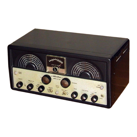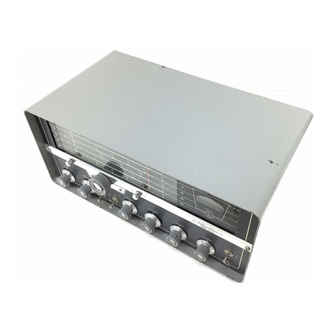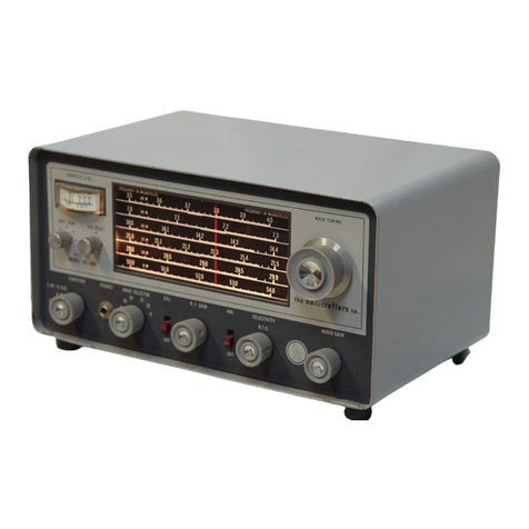
An
"S"
meter
is
used
when
receiving
AM
signals
to
indicate
the
accuracy
of tuning and the
relative
strength
of
received
signals.
The
meter
is
calibrated
in
microvolts,
"s"
units
from
1
to
9,
and in
decibels
above
S9
to
+ 80 db.
The
Receive-Standby
switch
on
the
front
panel
silences
the
receiver
but
leaves
the
heater
and
plate
power
on to
provide
instant
reception
between
transmission
periods.
Provision
has
also
been
made
in
the
receiver
for
remote
receive-standby
control, and for
transmitter
switching
from
the
front
panel.
Audio output connectionsinclude
terminals
for
a
3.
2-ohm
speaker
and a 500/600-ohm output
for
line
or
speaker.
A
front
panel jack
for
headphones
is
also
provided
and
the
speaker
is
automatically
silenced
when
the
headphoneplug
is
inserted.
A phono input
jack
at
the
rear
of
the
receiver
permits
attachment
of a
record
player.
The
receiver
is
designed
to
operate
on 105
to
125 volt, 50/60 cycle
AC
current.
Provision
is
also
made
in
the
receiver
for
operation
from
an
external
DC
power
supply
or
batteries
in
areas
where
AC
power
is
not available.
SECTION
2.
INSTALLATION
2-1. UNPACKING
After unpacking
the
receiver,
examine
it
closely
for
damage which
may
have
occured
in
transit.
Should any
Signof
damage
be
apparent,
file
a
claim
immediately
with
the
carrier
stating
the
extent
of damage. Carefully check
all
shipping
labels
and
tags
for
instructions
before
removing
or
destroying
them.
2-2.
LOCATION
The
receiver
may
be
placed
in any
location
that
will
permit
free
air
circulation
through
the
ventilation
holes
and openings in
the
cabinet. Avoid
excessively
warm
locations
such
as
those
near
radiators
and heating vents.
The
external
speaker
may
be
located
in any convenient pOSition although
it
is
recommended
that
it
not be
placed
on top of
the
receiver
for
reasons
of ventilation.
2-3.
ANTEN
NAS
The
r-f
inputof
the
receiver
is
designed
for
operation
form
either
a
single-wire
antenna,
or
a
half-wave
doublet
or
other
tuned
antenna
with
transmission
line
impedances
from
52
to 600 ohms. Antenna connections
are
made
to a
three
terminal
strip
at
the
rear
of the
receiver
marked
"A1",
"A2",
and "G". Mounting holes
are
also
provided,
ad-
jacent
to
the
antenna
terminals,
for
installation
of an
AN
type SO-239 connector
for
coaxial cable
installations.
A. SINGLE WIRE ANTENNA
The
Simplest
antenna
and one which will
provide
satisfactory
results
throughout
the
entire
tuning
range
is
a conventional
single-wire
antenna.
In
most
localities,
good
results
can
be
obtained with
just
the
15-foot
length
of
antenna
wire
suppliedwith
the
receiver.
(See Fig.
2.)
Simply
attach
one end of
this
wire
to
terminal"
A1", and
"G",
and then
run
the
wire
about
the
room
in any con-
venient
manner.
If
the
receiver
is
operated
in a
steel
constructed
building
or
where
receiving
conditions
are
exceptionally
poor,
an
outside
antenna,
50
to
100
feet
long, may
be
necessary.
The
outside
antenna should
be
erected
as
high
as
possible
and kept
free
from
surround-
ingobjects. In
some
locations,
reception
may
be
improv-
ed
by
connecting a ground
wire
(ordinary
copper
wire)
from
terminal"
G"
to
a cold
water
pipe
or
outside
ground
rod. While
the
use
of an
outside
ground
rod
installed
in
accordance
with
Insurance
Underwriter's
Laboratories
requirements
is
adequate
protection
against
lightning, we
strongly
recommend
anadditional connection
to
the
near-
est
cold
water
pine
to
eliminate
any
shock
hazard.
B.
HALF·WAVE
DOUBLET
ANTENNA
For
top
performance,
especially
on
the
short-
wave and
amateur
bands,
the
use
of a
half-wave
doublet
or
other
type
of antennaemployinga
52
to
600-ohm
trans-
mission
line
is
recommended.
A
typical
doublet
antenna
installation
is
shown in Fig.
3.
The
double
antenna
should
be
cut
to
the
proper
length
for
the
most
used
fre-
-3-
9261391-C
Fig.
2. Single
Wire
Antenna
Fig
..
3.
Doublet Antenna Using
Twin-Lead
Transmission
Line
