FACTORY RESET CIRCUIT DISCONNECT (AIR-GAP)
ONLY DOTHIS STEP IF YOU ARE UNABLETO REMOVETHE
DEVICE USINGTHE APP.
If removal does not work, delete it in the app by clicking “my
device is broken” and then follow the factory reset steps:
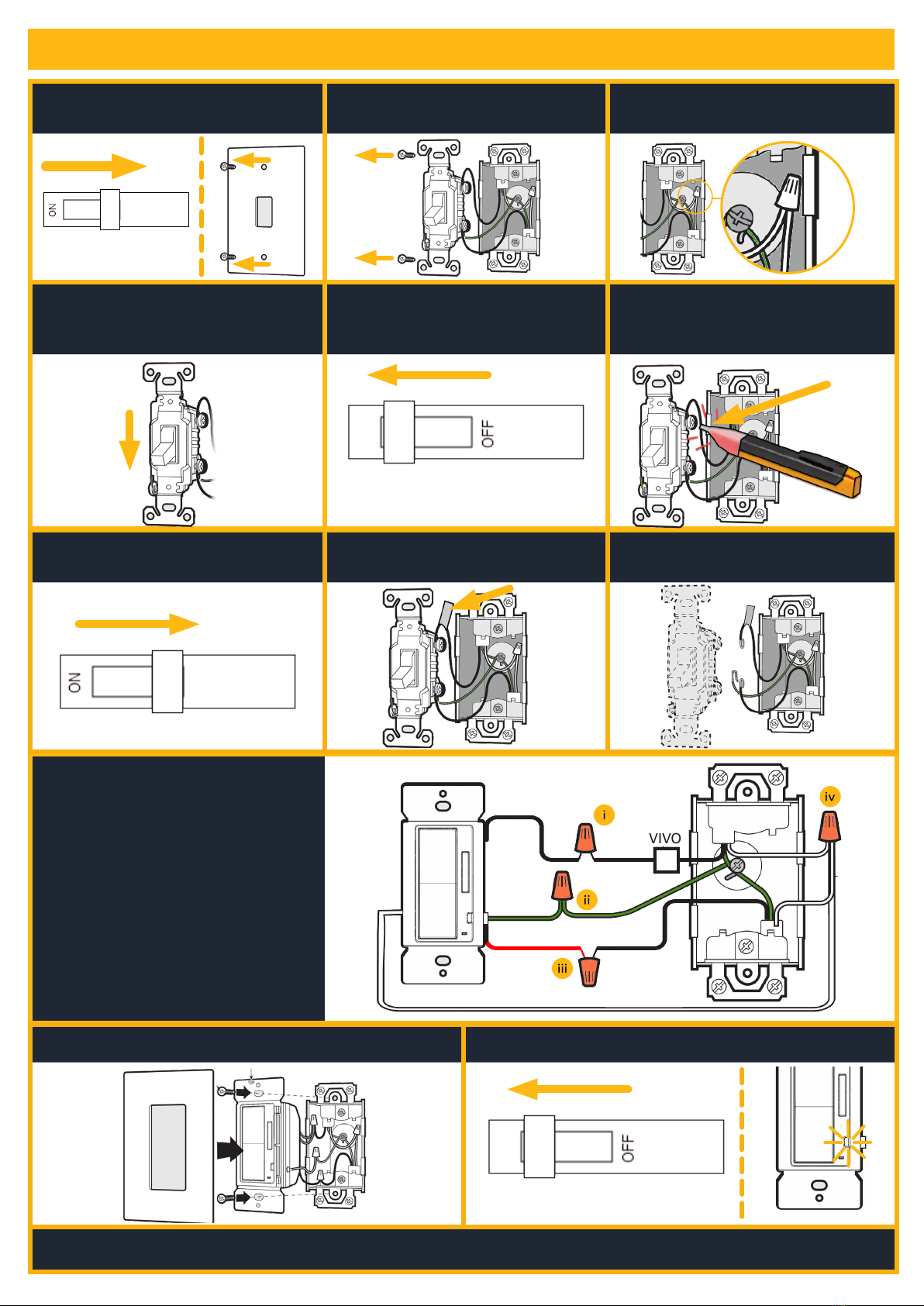
1. Press and hold the ON button for 12 seconds to reset.
2. The load may turn OFF or ON and the LED will start flashing
indicating the reset is processing.The LED will continue
flashing to indicate that the dimmer is ready to be paired
with the HALO Home App.
Construction of control: Independently
Mounted for Flush Mounting
Type of Action: Type 1.B Action
Pollution Degree: 2
Rated Impulse Voltage: 2500 V
Software Class: Class A
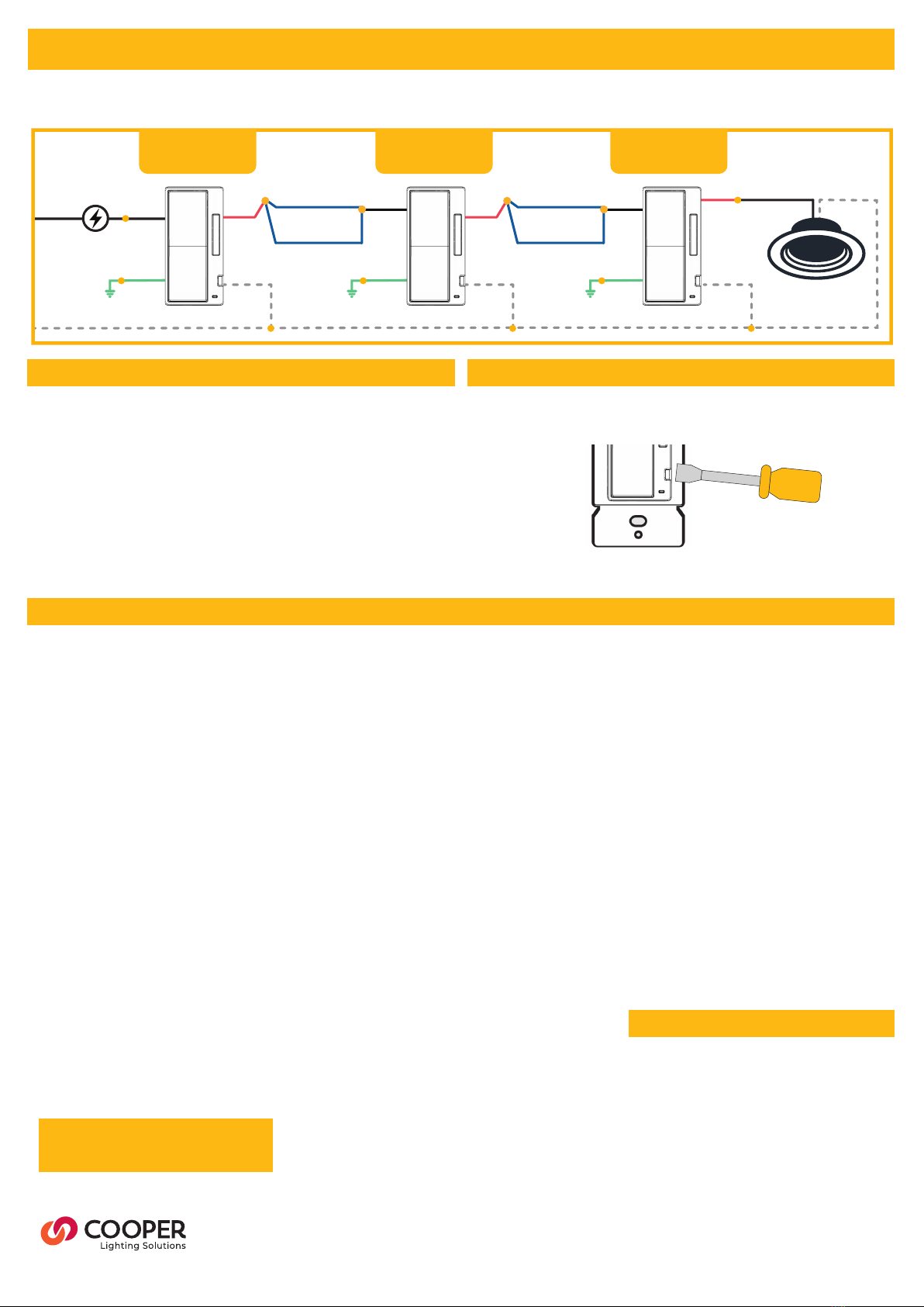
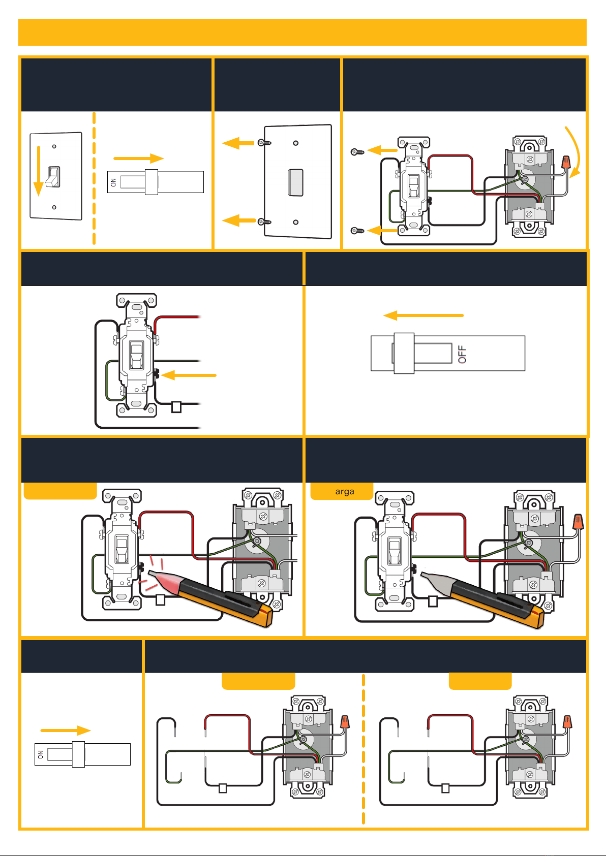
Disconnect power to this dimmer and any connected loads by
using a flathead screwdriver to pull the air-gap dimmer out until
you hear a click.
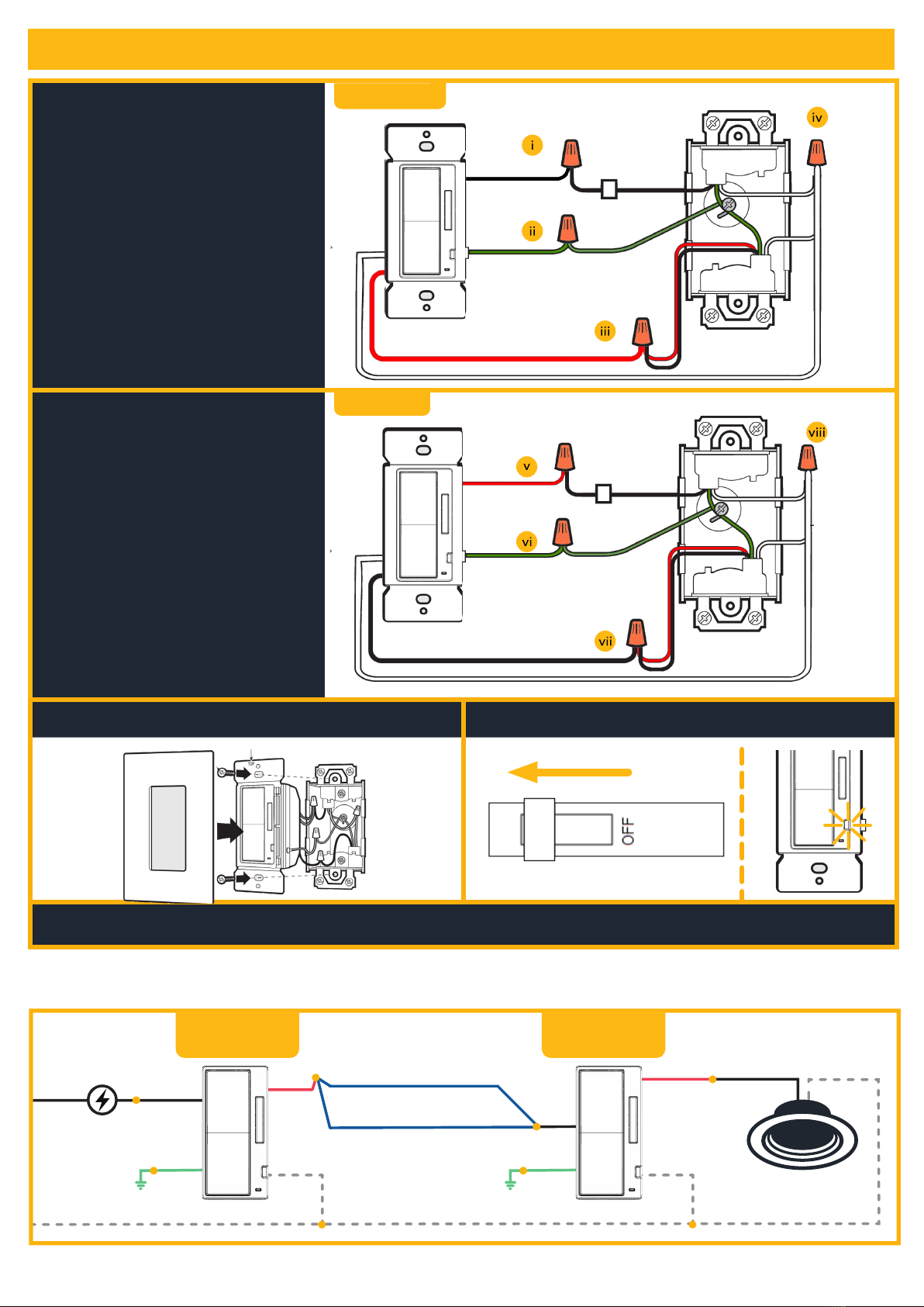
4-WAY INSTALLATION (3+ Dimmers) Continued
4-WAY WIRING DIAGRAM
RedLoad
Red
Hot
Neutral
Neutral
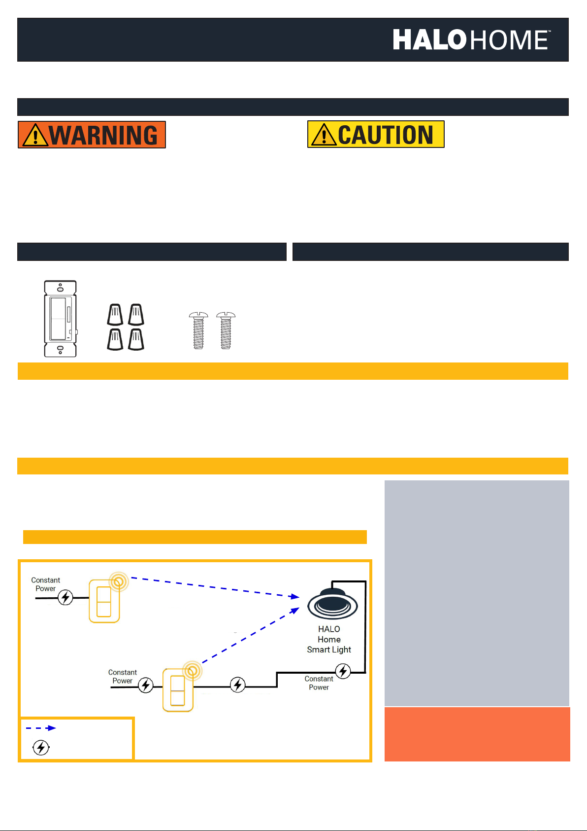
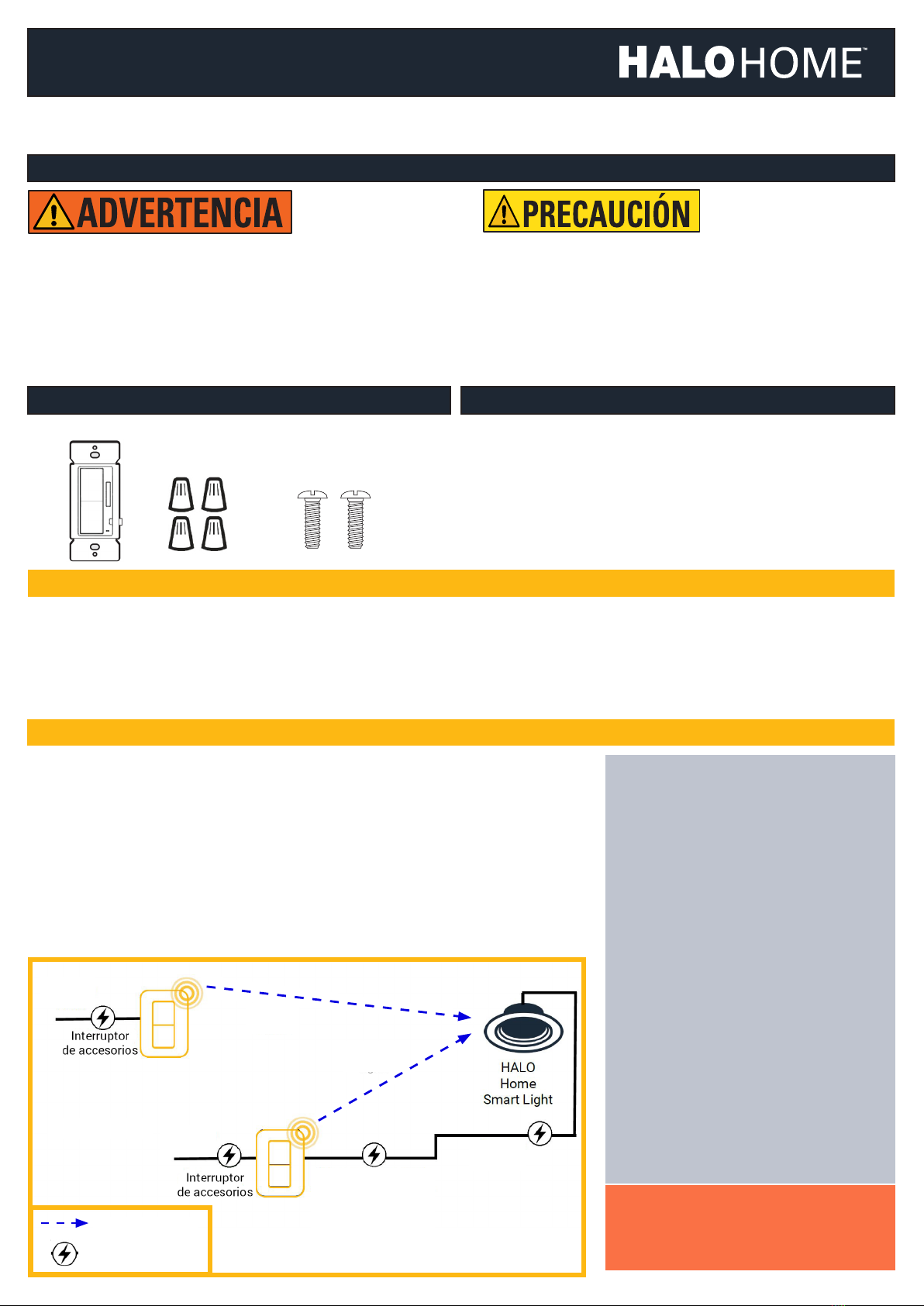
HALO Home
Smart Light(s)
Green
Ground
Traveler Wires
Black
Black
White White
Green
Ground
Accessory
Switch
Accessory
Switch
Smart
Switch
Red
Red
Load
Hot
Neutral
Neutral
Standard
Light(s)
Traveler Wires
Black
White
Green
Ground
Accessory
Switch
Accessory
Switch
White
Green
Ground
Red
Traveler Wires
Black
Black
White
Green
Ground
Red
Red
Load
Hot
Neutral
Neutral
Traveler Wires
Black
White
Green
Ground
Accessory
Switch
Accessory
Switch
Accessory
Switch
White
Green
Ground
Red
Traveler Wires
Black
Black
White
Green
Ground
HALO Home
Smart Light(s)
RedLoad
Red
Hot
Neutral
Neutral
Standard
Light(s)
Green
Ground
Traveler Wires
Black
Black
White White
Green
Ground
Smart
Switch
Accessory
Switch
RedLoad
Red
Hot
Neutral
Neutral
HALO Home
Smart Light(s)
Green
Ground
Traveler Wires
Black
Black
White White
Green
Ground
Accessory
Dimmer
Accessory
Dimmer
Smart
Dimmer
Red
Red
Load
Hot
Neutral
Neutral
Standard
Light(s)
Traveler Wires
Black
White
Green
Ground
Accessory
Dimmer
Accessory
Dimmer
White
Green
Ground
Red
Traveler Wires
Black
Black
White
Green
Ground
Red
Red
Load
Hot
Neutral
Neutral
Traveler Wires
Black
White
Green
Ground
Accessory
Dimmer
Accessory
Dimmer
Accessory
Dimmer
White
Green
Ground
Red
Traveler Wires
Black
Black
White
Green
Ground
HALO Home
Smart Light(s)
RedLoad
Red
Hot
Neutral
Neutral
Standard
Light(s)
Green
Ground
Traveler Wires
Black
Black
White White
Green
Ground
Smart
Dimmer
Accessory
Dimmer
Cooper Lighting Solutions
1121 Highway 74 South
Peachtree City, GA 30269
P: 770-486-4800
www.cooperlighting.com
© 2021 Cooper Lighting Solutions
All Rights Reserved.
Specifications and dimensions
subject to change without notice.
IL517015EN page 6
February 3, 2021 8:34 AM
FCC Statement
• This device complies with Part 15 of the FCC
Rules. Operation is subject to the following two
conditions:
• (1) This device may not cause harmful
interference.
• (2) This device must accept any interference
received, including interference that may
cause undesired operation.
ote:N The grantee is not responsible for any
changes or modifications not expressly
approved by the party responsible for
compliance. Such modifications could void the
user’s authority to operate the equipment.
ote:N This equipment has been tested and found
to comply with the limits for a Class B digital
device, pursuant to part 15 of the FCC Rules.
These limits are designed to provide reasonable
protection against harmful interference in a
residential installation.
• This equipment generates uses and can
radiate radio frequency energy and, if not
installed and used in accordance with the
instructions, may cause harmful interference
to radio communications. However, there is
no guarantee that interference will not occur
in a particular installation. If this equipment
does cause harmful interference to radio or
television reception, which can be determined
by turning the equipment off and on, the user is
encouraged to try to correct the interference by
one or more of the following measures:
• Reorient or relocate the receiving antenna.
• Increase the separation between the
equipment and receiver.
• Connect the equipment into an outlet on a
circuit different from that to which the receiver
is connected.
• Consult the dealer or an experienced radio/TV
technician for help
Supplier’s Declaration of Conformity
47 CFR § 2.1077 Compliance Information
Unique Identifier: 2AKCY-HIWAC1BLE40
Responsible Party – U.S. Contact Information
Cooper Lighting Solutions
1121 Highway 74 S
Peachtree City, GA 30269
www.cooperlighting.com
IC Statement
• This device contains licence-exempt
transmitter(s)/receiver(s) that comply with
Innovation, Science and Economic Development
Canada’s licence-exempt RSS(s). Operation
is subject to the following two conditions: 1.
This device may not cause interference. 2. This
device must accept any interference, including
interference that may cause undesired operation
of the device.
FCC ID: 2AKCY-HIWAC1BLE40
IC: 4706A-HIWAC1BLE40
SAVE THESE INSTRUCTIONS AND
WARNINGS.
FCC STATEMENT
SUPPLEMENTAL INFORMATION
5-YEAR WARRANTY
For warranty information, please visit
www.cooperlighting.com/legal
Accessory
Dimmer
Accessory
Dimmer
Accessory
Dimmer