manuals.online logo
Brands
  1. Home
  2. •
  3. Brands
  4. •
  5. Halo
  6. •
  7. Grill
  8. •
  9. Halo ELITE2B User manual

Halo ELITE2B User manual

Other Halo Grill manuals

Halo PRIME300 HS-1005-ANA User manual

Halo

Halo PRIME300 HS-1005-ANA User manual

Halo PRIME550 User manual

Halo

Halo PRIME550 User manual

Halo PRIME550 User manual

Halo

Halo PRIME550 User manual

Halo PRIME1100 User manual

Halo

Halo PRIME1100 User manual

Halo PRIME550 User manual

Halo

Halo PRIME550 User manual

Halo PRIME1500 User manual

Halo

Halo PRIME1500 User manual

Popular Grill manuals by other brands

LMS BBQ08873P owner's manual

LMS

LMS BBQ08873P owner's manual

Cookworks LW-8010A Care & instruction manual

Cookworks

Cookworks LW-8010A Care & instruction manual

Campingaz CV Instructions for use

Campingaz

Campingaz CV Instructions for use

Metos XBL Series Installation and operation manual

Metos

Metos XBL Series Installation and operation manual

Fiesta ET34567 Use and care instructions

Fiesta

Fiesta ET34567 Use and care instructions

Mayer Barbecue BRENNA MKG-318A BASIC Assembly instructions

Mayer Barbecue

Mayer Barbecue BRENNA MKG-318A BASIC Assembly instructions

Landmann Avalon PTS Plus 5.1 Plus 12122 Assembly and operating manual

Landmann

Landmann Avalon PTS Plus 5.1 Plus 12122 Assembly and operating manual

Kenyon B70200 owner's manual

Kenyon

Kenyon B70200 owner's manual

Better Homes and Gardens GBC1486W owner's manual

Better Homes and Gardens

Better Homes and Gardens GBC1486W owner's manual

Orbegozo GR 2300 instruction manual

Orbegozo

Orbegozo GR 2300 instruction manual

bora PT11 Operating and installation instructions

bora

bora PT11 Operating and installation instructions

Klarstein 10031664 manual

Klarstein

Klarstein 10031664 manual

Garland MWE3W Installation and operation manual

Garland

Garland MWE3W Installation and operation manual

Char-Broil 463722714 Product guide

Char-Broil

Char-Broil 463722714 Product guide

MPM MOP-03 user manual

MPM

MPM MOP-03 user manual

Kenmore 415.16123800 Use and care guide

Kenmore

Kenmore 415.16123800 Use and care guide

Tucker Barbecues GTR Series Assembly, installation and operating instructions

Tucker Barbecues

Tucker Barbecues GTR Series Assembly, installation and operating instructions

Monogram ZGG540NCP1SS owner's manual

Monogram

Monogram ZGG540NCP1SS owner's manual

manuals.online logo
manuals.online logoBrands
  • About & Mission
  • Contact us
  • Privacy Policy
  • Terms and Conditions

Copyright 2025 Manuals.Online. All Rights Reserved.

QUICK START GUIDE
HZ-1003-XNA
w
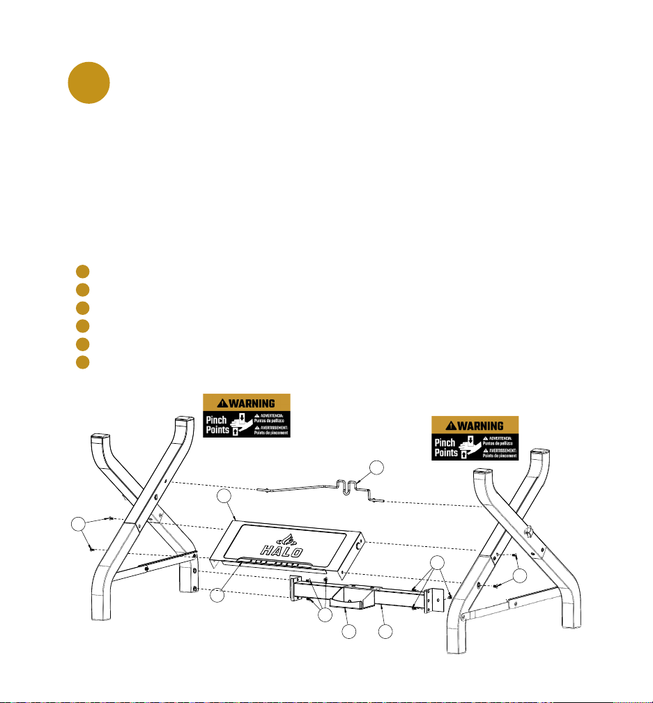
The manufacturer has made every effort to eliminate any sharp edges. However, you should handle all components
with care to avoid accidental injury.
WARNING
NOTICE: Before assembly, make sure all parts are present. If any part is missing or damaged, do not
attempt to assemble the appliance. Contact customer service for replacement parts at 1-833-572-1688.
El fabricante ha hecho todo lo posible para eliminar los bordes alados. Sin embargo, debe manipular todos los
componentes con cuidado para evitar lesiones accidentales.
ADVERTENCIA
AVISO: Antes del montaje, asegúrese de que todas las piezas están presentes. Si falta alguna pieza o
está dañada, no intente montar el aparato. Póngase en contacto con el servicio de atención al cliente
para obtener piezas de repuesto al teléfono 1-833-572-1688.
BATTERY NOT INCLUDED. Requires 1 AA battery for igniter.
NEED MORE INSTRUCTIONS?
Scan for registration, assembly videos,
care + use, warranty, recipes, + more.
¿NECESITA MÁS INSTRUCCIONES?
Busque registro, vídeos de montaje, cuidados y uso, garantía, recetas y mucho más.
VOUS AVEZ BESOIN DE PLUS D’INSTRUCTIONS?
Recherchez l’enregistrement, les vidéos de montage, l’entretien et l’utilisation, la
garantie, les recettes et bien plus encore.
BATERÍA NO INCLUIDA. Requiere una batería AA para el encendedor.
Le fabricant a fait tout son possible pour éliminer les arêtes vives. Cependant, vous devez manipuler tous les
composants avec précaution pour éviter toute blessure accidentelle.
AVERTISSEMENT
AVIS: Avant l’assemblage, assurez-vous que toutes les pièces sont présentes. Si une pièce est
manquante ou endommagée, n’essayez pas d’assembler l’appareil. Contactez le service à la clientèle
pour obtenir des pièces de rechange au 1-833-572-1688.
LES PILE NE SONT PAS INCLUSES. Nécessite 1 pile AA pour l’allumeur.
3
w
IMPORTANTE: Lea detenidamente todas las instrucciones antes de proceder. Encuentre una zona amplia y
limpia para armar su Plancha de Exteriores HALO Elite2B. Si es necesario, consulte el esquema de montaje.
IMPORTANT: Veuillez lire attentivement toutes les instructions avant de procéder. Trouvez un endroit large
et propre pour assembler votre Gril d'extérieur HALO Elite2B. Veuillez vous référer au schéma de montage, si
nécessaire.
IMPORTANT: Please read all instructions thoroughly before proceeding. Find a large, clean area in which to
assemble your HALO Elite2B Outdoor Griddle. Please refer to the assembly diagram, as necessary.
Install left outer leg using 3-M6 x 14 mm
screws. Install leg cap.
1
Cap-Leg
Left-Outer Leg-Long
Left-Outer Leg-Short
M6 x 14 mm Screw
ITEM PART DESCRIPTION
31
32
32A
46
QTY.
1
1
1
3
PART #
HZ-1001-48
HZ-1001-49
HZ-1001-50
HZ-1001-40
Tool required for assembly: #2 Phillips Screwdriver
NOTICE: Make sure all the plastic protection is removed before assembling.
Instale la pata exterior izquierda con 3 tornillos M6 x 14 mm. Instale la tapa de la pata.
Installez le pied extérieur gauche à l'aide de vis 3-M6 x 14 mm. Installez le capuchon du pied.
AVISO: Asegúrese de retirar todas las protecciones de plástico antes de realizar el montaje.
AVIS : Assurez-vous que toutes les protections en plastique sont retirées avant de procéder à
l'assemblage.
Herramienta necesaria para el montaje: Destornillador Phillips #2
Outil requis pour l'assemblage : tournevis cruciforme nº2
32
46
46
46
31
32A
4
2Install left inner leg using 3-M6 x 14 mm
screws. Install leg cap.
Cap-Leg
Left-Inner Leg-Long
Left-Inner Leg-Short
M6 x 14 mm Screw
ITEM PART DESCRIPTION
31
33
33A
46
QTY.
1
1
1
3
PART #
HZ-1001-48
HZ-1001-51
HZ-1001-52
HZ-1001-40
Instale la pata interior izquierda con 3 tornillos M6 x 14 mm. Instale la tapa de la pata.
Installez le pied intérieur gauche à l'aide de vis 3-M6 x 14 mm. Installez le capuchon du pied.
31
33
46
46
33A
46
5
51
41
49
49
47
41A
Install left outer leg assembly and right inner
Leg assembly using pivot bracket 41 and 41A,
2-M6 x 3H Shoulder screws, M6 x 93 mm knob
with threaded shaft and nylon spacer. Tighten
screws firmly. Set assembly aside.
3
Pivot Bracket-A
Pivot Bracket-B
M6 x 93 mm Knob with Threaded Shaft
M6 x 3H Shoulder Screw
Nylon Spacer
ITEM PART DESCRIPTION
41
41A
QTY.
1
1
1
2
1
PART #
HZ-1001-36
HZ-1001-37
HZ-1001-41
HZ-1001-43
HZ-1001-45
47
49
51
Instale el conjunto de la pata exterior izquierda y el conjunto de la pata interior derecha utilizando
el soporte de pivote 41 y 41A, 2 tornillos de Tope M6 x 3H, perilla M6 x 93 mm con eje roscado y
espaciador de nylon. Apriete bien los tornillos. Aparte el montaje.
Installez l'ensemble pied extérieur gauche et l'ensemble pied intérieure droit en utilisant le support
de pivot 41 et 41A, les vis à épaulement 2-M6 x 3H, le bouton M6 x 93 mm avec l'arbre leté et
l'entretoise en nylon. Serrez les vis fermement. Mettez l'ensemble de côté.
4
6
Install right inner leg assembly using
3-M6 x 14 mm screws. Install leg cap.
Cap-Leg
Right-Inner Leg-Long
Right-Inner Leg-Short
M6 x 14 mm Screw
ITEM PART DESCRIPTION
31
34
34A
46
QTY.
1
1
1
3
PART #
HZ-1001-48
HZ-1001-53
HZ-1001-54
HZ-1001-40
Instale el conjunto de la pata interior derecha con 3 tornillos M6 x 14 mm. Instale la tapa de la pata.
Installez l'assemblage du pied intérieur droit à l'aide de vis 3-M6 x 14 mm. Installez le capuchon du pied.
31
34
34A
46
46
46
7
Install right outer leg assembly using
3-M6 x 14 mm screws. Install leg cap.
5
Cap-Leg
Right-Outer Leg-Long
Right-Outer Leg-Short
M6 x 14 mm Screw
ITEM PART DESCRIPTION
31
35
35A
46
QTY.
1
1
1
3
PART #
HZ-1001-48
HZ-1001-55
HZ-1001-56
HZ-1001-40
Instale el conjunto de la pata exterior derecha con 3 tornillos M6 x 14 mm. Instale la tapa de la pata.
Installez l'assemblage du pied extérieur droit à l'aide de vis 3-M6 x 14 mm. Installez le capuchon du pied.
31
35
46
46
35A
46
8
Install right outer leg assembly and right inner
leg assembly using pivot bracket 42 and 41A,
2-M6 x 3H shoulder screws, M6 x 93 mm knob
with threaded shaft and nylon spacer. Tighten
screws firmly. Set assembly aside.
6
Pivot Bracket-B
Pivot Bracket-C
M6 x 93 mm Knob with Threaded Shaft
M6 x 3H Shoulder Screw
Nylon Spacer
ITEM PART DESCRIPTION
41A
42
47
49
QTY.
1
1
1
2
1
PART #
HZ-1001-37
HZ-1001-38
HZ-1001-41
HZ-1001-43
HZ-1001-45
51
Instale el conjunto de la pata exterior derecha y el conjunto de la pata interior derecha utilizando
el soporte de pivote 42 y 41A, 2 tornillos de Tope M6 x 3H, perilla M6 x 93 mm con eje roscado y
espaciador de nylon. Apriete bien los tornillos. Aparte el montaje.
Installez l'ensemble pied extérieur droit et l'ensemble pied intérieur droit en utilisant le support
de pivot 42 et 41A, les vis à épaulement 2-M6 x 3H, le bouton M6 x 93 mm avec l'arbre leté et
l'entretoise en nylon. Serrez les vis fermement. Mettez l'ensemble de côté.
9
Install tank retention support bracket and rear
brace using 2-M6 x 14 mm screws.
7
Tank Support Bracket
Rear Brace
M6 x 14 mm Screw
ITEM PART DESCRIPTION
37
38
46
QTY.
1
1
2
PART #
HZ-1001-32
HZ-1003-11
HZ-1001-40
Instale el soporte de retención del tanque y la abrazadera trasera con 2 tornillos M6 x 14 mm.
Installez le support de maintien du réservoir et le renfort arrière à l'aide de vis 2-M6 x 14 mm.
38
46
46
37
10
Install tank retention wire, front panel and rear
brace assembly using 10-M6 x 14 mm screws.
Tighten screws firmly.
8
IMPORTANT: Do not tighten screws completely until all screws for this step have been installed.
Tank Support Bracket
Rear Brace
M6 x 14 mm Screw
Front Panel
"RISE ABOVE" Logo Plate
Tank Retention Wire
ITEM PART DESCRIPTION
37
38
46
39
QTY.
1
1
10
1
1
1
PART #
HZ-1001-32
HZ-1003-10
HZ-1001-40
HZ-1003-11
HZ-1004-39
HZ-1003-09
Instale la retención del tanque, el panel frontal y el conjunto de la abrazadera trasera utilizando
10 tornillos M6 x 14 mm. Apriete bien los tornillos.
Installez le l de retenue du réservoir, le panneau avant et l'ensemble de renfort arrière à l'aide
de vis 10-M6 x 14 mm. Serrez les vis fermement.
IMPORTANTE: No apriete los tornillos completamente hasta que se hayan instalado todos los tornillos de este paso.
IMPORTANT : Ne serrez pas complètement les vis avant que toutes les vis de cette étape aient été installées.
46
36
39
40
3837
46
46
46
40
36