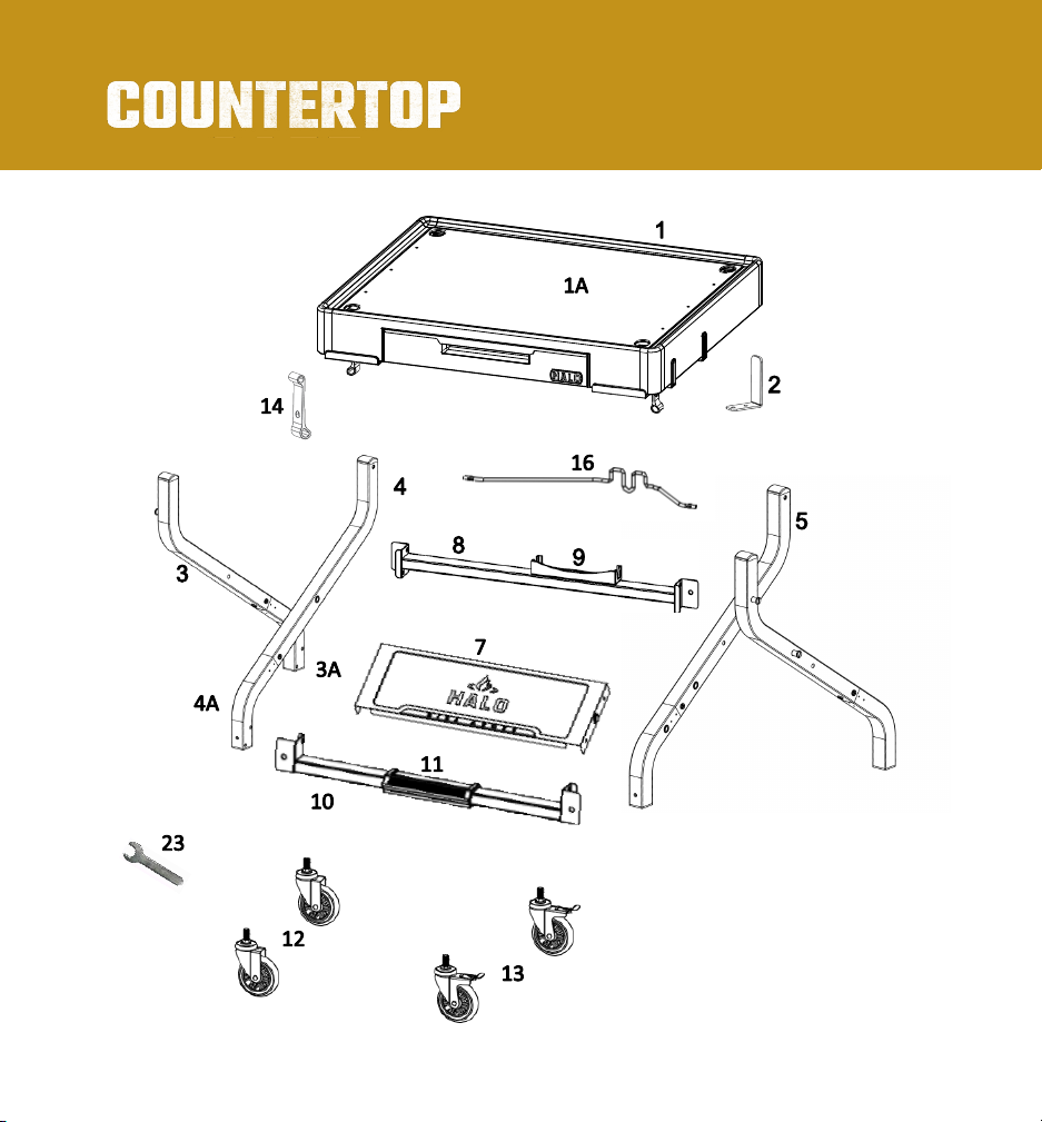
Halo HO-1006-XNA Manual

INSTRUCTION GUIDE
CARRO DE MESÓN
GUÍA DE INSTRUCCIONES
CHARIOT DE COMPTOIR
GUIDE D'INSTRUCTION
Model No: HO-1006-XNA

2
TABLE OF CONTENTS
04
ABOUT THE COUNTERTOP CART
05
FOR USE WITH THE VERSA 16 OUTDOOR PIZZA OVEN
AND PRIME 300 COUNTERTOP PELLET GRILL
06
OWNER'S MANUAL
11
ASSEMBLY INSTRUCTIONS
24
HOW TO COLLAPSE THE COUNTERTOP CART
08
COUNTERTOP CART PARTS LIST
07
PRODUCT INSTALLATION RECORD
10
ASSEMBLY PREPARATION
23
ASSEMBLED DIMENSIONS
25
FIVE (5) YEAR LIMITED WARRANTY

28
MANUAL DEL USUARIO
33
INSTRUCCIONES DE MONTAJE
30
LISTA DE PIEZAS DEL CARRO DE MESÓN
32
PREPARACIÓN DEL MONTAJE
DIMENSIONES DE MONTAJE 45
GARANTÍA LIMITADA DE CINCO (5) AÑOS 47
46
CÓMO COLAPSAR EL CARRO DE MESÓN
3
29
REGISTRO DE INSTALACIÓN DEL PRODUCTO
50
MANUEL DU PROPRIÉTAIRE
55
INSTRUCTIONS DE MONTAGE
52
LISTE DES PIÈCES DU CHARIOT DE COMPTOIR
54
PRÉPARATION DE L'ASSEMBLAGE
DIMENSIONS DE L'ASSEMBLAGE 67
GARANTIE LIMITÉE DE CINQ (5) ANS 69
68
COMMENT REPLIER LE CHARIOT DE COMPTOIR
51
DOSSIER D'INSTALLATION DU PRODUIT

ABOUT THE
The HALO Countertop Cart’s unique features perfectly pair with any Halo countertop
product. Free up clutter and keep your space clean with a hidden drop-down drawer,
strategically placed drainage holes, and a magnetic attachment to access cooking utensils.
Safely store your 20lb propane tank with a
lock-in-place setting at the
cart's rear base.
The CTC also has a 360-degree
rolling range and durable caster
wheels compatible with various
rolling surfaces, making it easy and
comfortable to transition from the
deck to outdoor terrain.
Easily collapsible, the simple
detach and drop detail makes it
perfect for the patio or on the go.
Outdoor storage never
looked so sleek!
4

PIZZA OVEN AND PELLET GRILL SOLD SEPARATELY
5

SCAN FOR
Product Registration
Online Owner’s Guide
Assembly Videos
6
OWNER'S MANUAL
MODEL NO: HO-1006-XNA
SAVE THIS MANUAL FOR FUTURE REFERENCE.
READ ALL INSTRUCTIONS BEFORE INSTALLING AND USING THE
COUTERTOP CART.
WARNING
This product can expose you to chemicals known to the
State of California to cause cancer and birth defects or
other reproductive harm. For more information go to
www.P65Warnings.ca.gov
WARNING
CALIFORNIA PROPOSITION 65

7
PRODUCT INSTALLATION RECORD
NOTICE: Model number
and Serial Number
located on bottom of the
drawer.
Model Number:
Serial Number: Purchase Date:
7
IMPORTANT:FILL OUT PRODUCT RECORD INFORMATION BELOW, OR
TO REGISTER YOUR PRODUCT, VISIT OUR WEBSITE AT halo-pg.com.

CART PARTS LIST
8
5A
6
6A
15
NOTE: Item 2 included in hardware pack.

CART PARTS LIST
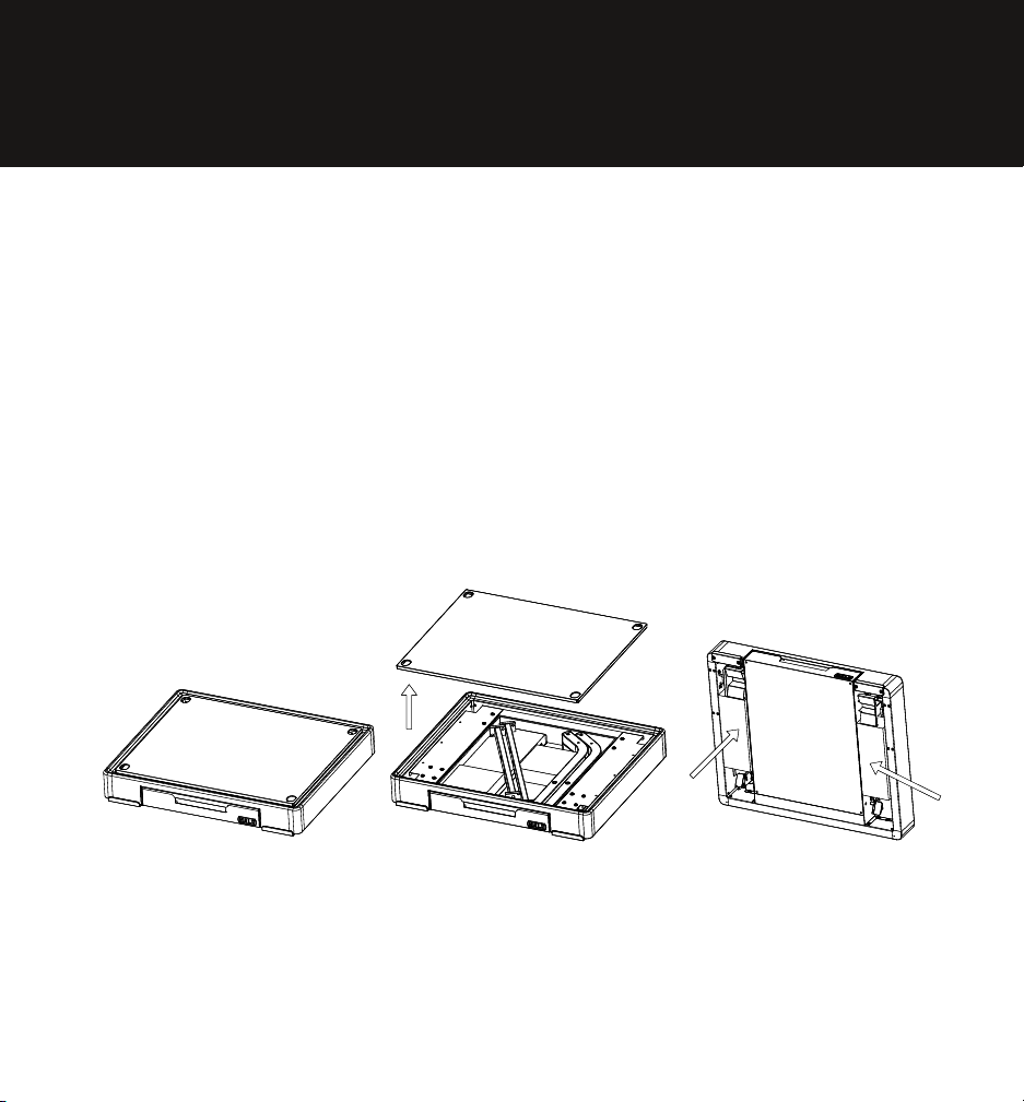
Countertop Assembly HO-1006-XNA-1 1
Countertop Panel HO-1006-XNA-1A 1
Magnetic Tool Hook HO-1006-XNA-2 4
Left-Outer Leg-Long HO-1006-XNA-3 1
Left-Outer Leg-Short HO-1006-XNA-3A 1
Left-Inner Leg-Long HO-1006-XNA-4 1
Left-Inner Leg-Short HO-1006-XNA-4A 1
Right-Inner Leg-Long HO-1006-XNA-5 1
Right-Inner Leg-Short HO-1006-XNA-5A 1
Right-Outer Leg-Long HO-1006-XNA-6 1
Right-Outer Leg-Short HO-1006-XNA-6A 1
Front Panel with Logo HO-1006-XNA-7 1
Rear Brace HO-1006-XNA-8 1
Tank Support Bracket HO-1006-XNA-9 1
Front Brace HO-1006-XNA-10 1
Footrest Pad HO-1006-XNA-11 1
Caster-Non-swivel HO-1006-XNA-12 2
Caster-with Lock HO-1006-XNA-13 2
Latch-Common HZ-1004-03 2
Leg Cap HO-1006-XNA-14 4
Tank Retention Wire HO-1006-XNA-15 1
Hardware Blister Pack HO-1006-XNA-16 1
M6 x 14 Screw HO-1006-XNA-17 26
M4 x 12 Screw HO-1006-XNA-17A 14
M6 Shoulder Screw HO-1006-XNA-19 4
Leg Bushing HO-1006-XNA-20 2
M6 Knob with Threaded Shaft HO-1006-XNA-21 2
8mm Pivot Pin HO-1006-XNA-22 2
Cotter Pin HO-1006-XNA-23A 2
Flat Washer HO-1006-XNA-23B 2
17mm Caster Wrench HO-1006-XNA-23 1
ITEM PART DESCRIPTION PART NO.
1
1A
2
3
3A
4
4A
5
5A
6
6A
7
8
9
10
11
12
13
14
15
16
17
18
QTY.
18A
19
20
21
9
22
22A
22B
23

1010
IMPORTANT: It is advised to read each step entirely before starting assembly on
instructions. Do not tighten screws completely until all screws for that step have
been installed.
ASSEMBLY PREPARATION
Parts are located throughout the shipping carton, including inside the
drawer. Inspect all parts, and hardware blister pack after removing from
the protective shipping carton. Discard all packaging materials from
inside and outside of the cart before assembly, then review and inspect
all parts by referencing the parts list. If any part is missing or damaged,
do not attempt to assemble. Contact Halo Customer Service for parts.
Halo Customer Service:
Monday-Friday, 8am-5pm
Toll Free:1-833-572-1688
NOTE: The packaging carton can be attened and use as protective pad to help
painted surface from scratch during assembly.

Install Left Outer Leg using 3-M6 x 14
screws, install Leg Cap.
1
Tool required for assembly: #2 Phillips Screwdriver
11
IMPORTANT: Do not
tighten screws completely
until all screws for that
step have been installed.
3
3A
15
19
18
Left-Outer Leg-Long 1
Left-Outer Leg-Short 1
M6 x 14 Screw 3
Shoulder Screw 2
Leg Cap 1
ITEM PART DESCRIPTION
3
3A
18
19
15
QTY.

12
2
IMPORTANT: Do not
tighten screws completely
until all screws for that
step have been installed.
Left-Inner Leg-Long 1
Left-Inner Leg-Short 1
M6 x 14 Screw 3
Leg Cap 1
ITEM PART DESCRIPTION
4
4A
18
15
QTY.
4
4A
15
18
Install Left Inner Leg using 3-M6 x 14
screws, install Leg Cap.

Install Left Outer Leg assembly and Left
Inner Leg assembly using M6-Knob with
Threaded Shaft, placing Leg Bushing in
between. Set assembly aside.
3
13
20
21
3/3A
4/4A
Left Outer Leg Assembly 1
Left Inner Leg Assembly 1
Leg Bushing 1
M6 Knob with Threaded Shaft 1
ITEM PART DESCRIPTION
3
4
20
21
QTY.
3A
4A

4
14
IMPORTANT: Do not
tighten screws completely
until all screws for that
step have been installed.
Right-Inner Leg-Long 1
Right-Inner Leg-Short 1
M6 x 14 Screw 3
Leg Cap 1
ITEM PART DESCRIPTION
5
5A
18
15
QTY.
Install Right Inner Leg assembly using
3-M6 x 14 screws, install Leg Cap.
15
5
5A
18

15
Install Right Outer Leg assembly using
3-M6 x 14 and 2-M6 shoulder screws.
5
IMPORTANT: Do not
tighten screws completely
until all screws for that
step have been installed.
6
15
6A
19
Right-Inner Leg-Long 1
Right-Inner Leg-Short 1
M6 x 14 Screw 3
M6 Shoulder Screw 2
Leg Cap 1
ITEM PART DESCRIPTION
6
6A
18
19
QTY.
15

16
Install Right Inner Leg assembly and
Right Outer Leg assembly using M6-
Knob with Threaded Shaft and Leg
Bushing and tie firmly.
6
Right Inner Leg Assembly 1
Right Outer Leg Assembly 1
Leg Bushing 1
M6 Knob with Threaded Shaft 1
ITEM PART DESCRIPTION
5
6
20
21
QTY.
5A
6A
20 21
5
6
5A 6A

17
Install Tank Retention and Rear Brace
using 6-M6 x 14 screws.
7
IMPORTANT: Do not
tighten screws completely
until all screws for that
step have been installed.
NOTE: Tie all screws with hand tie and wait until next step.
16
8/9
4/4A
3/3A 5/5A
6/6A
Left Outer Leg Assembly 1
Left Inner Leg Assembly 1
Right Inner Leg Assembly 1
Right Outer Leg Assembly 1
Rear Brace, Tank Support Assembly 1
Tank Retention Wire 1
M6 x 14 Screw 6
ITEM PART DESCRIPTION
3
4
16
18
QTY.
3A
4A
5
6
5A
6A
8 9
18
18

7
10/11
18
18
18
Install Front Panel and Front Brace
using 8-M6 x 14 screws.
8
Front Panel with Logo 1
Front Brace 1
M6 x 14 Screw 8
ITEM PART DESCRIPTION
7
10
18
QTY.
11
IMPORTANT: Do not
tighten screws completely
until all screws for that
step have been installed.
NOTE: Tie all screws rmly.

19
Install Magnetic Tool Hooks using
8-M4 x 12 screws.
9
1
18A
2
18A
Countertop Panel 1
Magnetic Tool Hook 4
M4 x 12 Screw 8
ITEM PART DESCRIPTION
1A
2
18A
QTY.

20
Install Cart assembly to Countertop
using 2-8mm Pivot Pins and fasten
Latches in place.
10
Countertop Assembly 1
Latch 2
Cart Assembly 1
8mm Pivot Pin 2
Cotter Pin 2
Flat Washer 2
ITEM PART DESCRIPTION
1
14
QTY.
22
22
B
B
22
14
14
SECTION B-B
22B
22A
22
22A
22B
N/A
Table of contents
Languages: