Halo Lite RF User manual

i
d
e
a
l
h
e
a
t
i
n
g
.
c
o
m
H
a
l
o
L
i
t
e
R
F
I
n
s
t
a
l
l
a
t
i
o
n
G
u
i
d
e

2
The code of practice for the installation, commissioning
& servicing of central heating systems

3
CONTENTS
1. Kit Contents..................................................................................................................................................... 4
2. Halo LITE RF.....................................................................................................................................................5
3. Safety Information......................................................................................................................................5
4. Location Guidelines..................................................................................................................................6
5. Installation of the Halo Lite RF Receiver................................................................................8
5.1 Installing the Halo Lite RF Receiver into a Boiler..........................................10
5.2 Installing the Halo Lite RF Receiver into a Logic Air Heat Pump.......12
6. Installing the Halo PRT ........................................................................................................................13
6.1 Wall Mounting ..............................................................................................................................13
6.2 Desk Mounting.............................................................................................................................14
6.3 Pairing...................................................................................................................................................15
7. Halo Features and Configuration..............................................................................................16
8. Halo Lite RF Receiver LED key......................................................................................................17
9. Advanced Settings...................................................................................................................................18
10. Commissioning Checklist.................................................................................................................19
11. Trouble Shooting..................................................................................................................................... 20

4
H. SAP registration label J. Screws & RawlplugsTM
F. Installation guide
G. User guide
I. 4 x AA batteries
1. KIT CONTENTS
A. Halo Lite RF PRT Front
Housing
C. Trim plate
D. Desk stand E. Halo Lite RF Receiver
B. Rear housing
Model Name:
Halo Lite RF
Model Qualier:
ErP Class V or ErP Class VI
I certify that this heat source is connected to
a compensation controller as indicated:
Halo Lite RF Enhanced Load
Compensator with OpenTherm Ideal
boiler (Class V)
Halo Lite RF with OpenTherm Ideal
Boiler and OS2 Weather Compensator
Temperature Sensor (Class VI)
Halo Lite RF and Ideal Heat Pump with
Weather Compensator (Class VI)
This product is compatible with the heat source
and provides compensation control that has
been permanently enabled. The heat source
has been commissioned in accordance with the
manufacturer’s instructions which have been
supplied to the householder.
Signed
Date
UIN 237462 A01

5
2. HALO LITE RF
Product Code: 237423
Wireless Programmable Room Thermostat (PRT)
ERP Details:
Halo Lite RF enhanced load compensator with
OpenTherm Ideal boiler (Class V)
Halo Lite RF with OpenTherm Ideal boiler & OS2
weather compensator temperature sensor (Class
VI)
Halo Lite RF & Ideal Heat Pump with weather
compensator (Class VI)
Compatible with the following boilers :
Atlantic Combi, Classic Combi², Esprit Eco Combi²,
Exclusive Combi², Instinct Combi², I-mini Combi²,
Independent Combi², Logic Combi ESP1, Logic
Code Combi ESP1, Logic Combi², Logic Combi²
IE, Logic+ Combi², Logic Max Combi², Logic Max
Combi² IE, Vogue Gen2 Combi, Vogue Max Combi,
Vogue Max Combi IE.
Compatible with the following heat pumps:
Logic Air
For a full list of compatible products, please visit
Idealheating.com
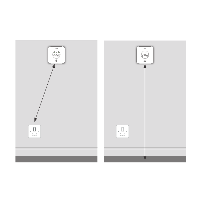
The Ideal Halo Lite RF is a wireless PRT with a wired
receiver to the boiler or heatpump
The Halo unit is powered by 4 AA batteries and
communicates with the Halo Lite Receiver unit on
a 868MHz frequency, a local RF protocol.
3. SAFETY INFORMATION
The Halo Lite RF must be installed by a competent
person with the appropriate safety qualifications.
Please read the instructions carefully. Failure to
follow these instructions can damage the product
or cause a hazardous condition.
These instructions are applicable to the Ideal
Boiler / heat pump models stated and must not
be used with any other make or model of boiler.
This product must be installed to all applicable
standards.
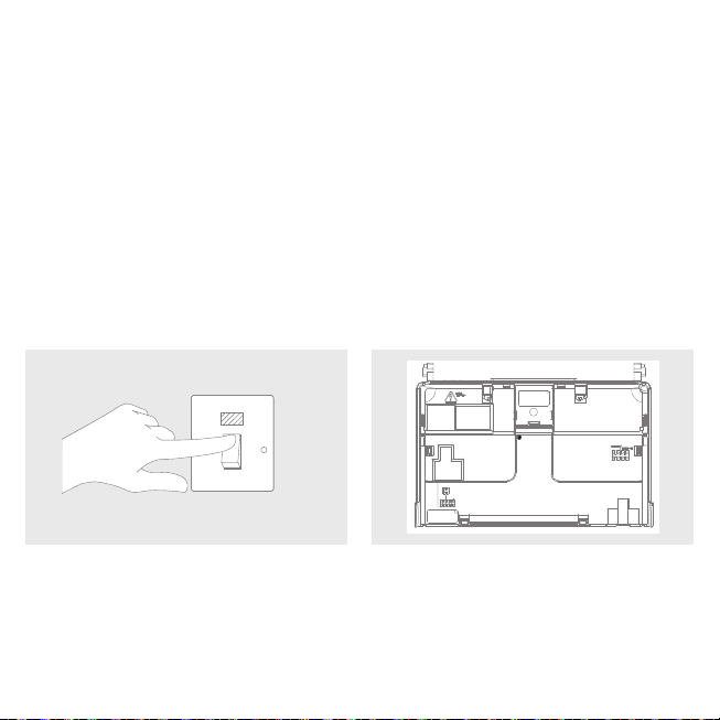
Always isolate the mains supply before installing
or working on any components relating to the
boiler or heat pump electronics.

6
4. LOCATION GUIDELINES
The Halo uses wireless RF communication between the control and the Reciever,
up to a maximum range of 30 metres. Occasionally house construction and materials can reduce this
communication range and it is advisable, where possible, to try and avoid directing communication through
metal frames or solid concrete walls
A. Mounted 1 m above the floor.
1 m
B. Not above radiator/heat source. C. Not in direct sunlight.
D. Away from any draughts. E. Not fitted behind curtains. F. Internal use only.

7
At least 1m
G. The receiver should be mounted close to a
230 Vac fused supply.
H. The receiver should be mounted
horizontally on the wall at least 1m from
the floor.

8
A. Using a suitable screwdriver turn the locking key one quarter turn anticlockwise to the [UNLOCK]
position. Remove the front panel by lifting the bottom edge first. Assemble in reverse order. Always
remember to lock the front panel to the Halo Lite Receiver. The receiver is supplied out of the box in
the [UNLOCK] position.
B. To mount directly onto the wall, mark and drill
mounting holes and fix the bracket to the wall
using suitable fixings for the wall type.
C. To mount over the electrical box, place the
bracket over the electrical box and fix into
place.
5. INSTALLATION OF THE HALO LITE RF RECEIVER
The Halo Lite RF Receiver must be installed by a competent person with the appropriate safety
qualifications. All wiring must be adequately sheathed and insulated.
Isolate any 230 Vac mains supply to the Halo Lite RF Receiver and any other linked components
before commencing works.

9
D. Isolate mains supply. E. From the fuse spur wire the Live, Neutral and
Earth connections into the right hand side
connections marked L, N, (E). The wiring can
be rear entry or surface mounted.
If installing with an Ideal boiler continue to Section 5.1. If installing with a Logic Air Heat Pump go to
Section 5.2 on page 12.
OFF

10
A. Make sure mains supply is still isolated B. Remove boiler front panel and swing the
control box into the servicing position.
OFF
COMBI
FROST
OPTIONAL
STAT
TIMER
S
ROOM
TAT/
L N
MAINSIN
5.1 Installing the Halo Lite RF Receiver with a Boiler
The below refers to the Ideal logic2combi boilers. For other models, please refer to the boilers installation
manual to locate connections.
Wiring Guidelines
The Boiler connection to the Ideal Halo Lite RF receiver should only be wired into the OpenTherm low
voltage connection and should not be connected to a 230 Vac supply. If utilising existing wiring, please
ensure that the wiring is not connected to a 230 Vac supply.
Opentherm Cable Details:
• Length between receiver to boiler is 50 meters maximum
• Core diameter - 0.5 – 1.0 mm diameter should be used, multi strand should be tinned
• Should not be adjacent to any 230 Vac cabling

11
D. Locate the opentherm terminals (right hand
side). Remove the link if present.
E. Wire the Halo Lite RF receiver to the boiler using the Opentherm connections. (not polarity conscious).
Continue to Section 6.
C. Locate the mains wiring terminals (left
hand side). If removed, replace the mains
thermostat link.

12
A. Make sure mains supply is still isolated
C. Connect the Receiver to the relevant zone connection on the Logic Air control panel (For 2 zone
application wire into the second zone terminal).
B. Remove the 4 fixings displayed above and
remove outer cover.
OFF
5.2 Installing the Halo Lite RF Receiver with a Logic Air Heat Pump
ZONE 1
ON/OFF
THERMOSTAT

13
6. INSTALLING THE HALO PRT
6.1 Wall Mounting
The Halo can be either wall mounted or desk mounted using the integrated rear housing and desk stand.
If there are any concerns regarding signal strength and location of the wall mounted PRT it is advisable to
pair the control and check the signal strength before fixing to the wall.
Note: The PRT and Receiver are pre-paired. Please follow the sequence below.
A. The Halo can be installed with or without
the provided trim plate.
B. If no trim plate is required, use the rear housing of the
Halo to position the unit on the wall, alternatively secure
rear housing to trim plate. Take care not to over-tighten
the screws. Turn on power to Halo Lite RF Receiver.
C. Insert the 4 AA batteries provided into the front
housing of the Halo. Pay close attention that the
orientation of the batteries is as indicated in the
housing.
D. Locate the front housing (display) in position
perpendicular to the rear housing and clip
into place.
ON

14
6.2 Desk Mounting
A. Turn on power to Halo Lite RF Receiver. B. Insert the 4 AA batteries provided into the
front housing of the Halo. Pay close attention
that the orientation of the batteries is as
indicated in the housing.
C. Locate the front housing (display) in position
perpendicular to the rear housing and clip
into place.
D. Clip the combined rear housing and display
onto the desk stand.
ON

15
6.3 Pairing
A. After power has been established. The unit
will automatically pair to the PRT. Once this
is completed the Power and RF LED will be
solid Green
B. The device will prompt set up of the time and
date using an easy step by step process.
C. There is the opportunity to add an installer
contact phone number into the device at this
stage, if not changed this will default to the
Ideal Heating Customer Service number.
D. Once the setup is completed the home screen
will be shown.

16
7. HALO FEATURES AND CONFIGURATION
To enter the settings menu press the menu button.
Menu Options Action
Holiday
Holiday mode allows the device to be switched off for a pre-
defined period of time then automatically returns to the pre-
programmed heating schedule.
Timed heating schedule Set a heating schedule with up to six periods per day.
Support Includes information such as software version and key contact
numbers.
Fault page Shows the latest fault code and fault description.
Time and date Time and date are set on power up and can be adjusted via the
menu.
Advanced settings Advanced features of the device setup should be set by a
competent person.
Landlord settings Specific setting for landlords.

17
8. HALO LITE RF RECEIVER LED KEY
LED Status
Power
Green - Power on
No illumination - Power off
Boiler
Green - Demand
No illumination - No demand
RF
Solid green - Paired and communicating
Flashing green - Searching for PRT
Flashing red - Pairing mode
Solid red - lost connection to the PRT
Override
Green - Override active
No illumination - Override not active

18
9. ADVANCED SETTINGS
Advanced Settings should only be adjusted by a competent person, the wrong configuration can have a
detrimental effect on the thermostat and the heating system.
Description Factory Setting New Setting
Optimised start
Boiler or Heat Pump starts heating in advance of
schedule so heating reaches the required temperature
at the time specified.
OFF
Optimised stop
Boiler or Heat Pump stops heating in advance of
schedule so heating reaches the required temperature
at the time specified.
OFF
Delayed start
If the room temperature is close to target temperature
the heating start time is delayed to save energy.
OFF
Display tolerance
Select the display tolerance of the current room
temperature, this can be set at increments of 0.5 or
0.1 0C.
0.1 0C
Temperature offset
Fine tune the room temperature display -2.5 to 2.5 0C. 0
Daylight saving time
Automatically move to daylight saving. ON
Frost protection
The temperature that will be used to protect your
home when the thermostat is off. Can be set 5 - 16 0C.
5 0C
Service phone number
Opportunity to input installer contact number for
service reminders.
Ideal Heating
number

19
10. COMMISSIONING CHECKLIST
Description Confirmed
Halo PRT is positioned in the homeowners chosen location if desk mounted.
Check RSSI (Received Signal Strength Indication) of the 868MHz
wireless connection via support page on the PRT (access via the
menu).
Target RSSI between 0 and -65
and text green
On the Halo set the mode to AUTO then increase the temperature
to 30 °C.
Flame ON
Boiler ON
Boiler LED on Receiver ON
(Green)
On the Halo PRT set the mode to AUTO then decrease the
temperature to 5 °C.
Flame OFF
Boiler OFF
Boiler LED on Receiver OFF
Check the Receiver indication is correct. Power LED green
RF LED green
Full battery level indication on Halo home screen.
868MHz network icon is present on the Halo home screen.
The slide switch on the Halo Lite RF receiver is in the Auto position.
Time and date correct.
Installer contact details inputted if required.
Suitable schedule has been entered for the user.
General overview of operation provided to user - refer to user guide.
Any advanced settings changes have been recorded.
Remember to leave this guide with the householder.

20
No power LED on
Receiver
Check that the receiver is wired correctly.
Check that the power is on.
Boiler / Heat Pump fails
to call when increasing
target temperature on
the Halo
Check the target temperature is above current temperature.
Check that the Receiver power LED is green.
Check the Receiver is correctly wired into the boiler.
Halo PRT screen shows
failed to sync
Check Receiver RF LED is flashing green.
Check distance between Receiver and Halo PRT (see Section B).
In the support page the
868MHz is lower than
-65 and text red
Consider moving the Halo PRT closer to the Receiver.
11. TROUBLE SHOOTING (BOILER)
Other manuals for Lite RF
1
Table of contents
Other Halo Vacuum Cleaner manuals
Popular Vacuum Cleaner manuals by other brands

Rowenta
Rowenta X-TREM POWER RO432311 manual

Moulinex
Moulinex POWERSTYLE manual

Nilfisk-Advance
Nilfisk-Advance WhisperClean supplementary guide

Bissell
Bissell healthy home 5770 SERIES user guide

DAY Useful Everyday
DAY Useful Everyday 721996 instruction manual

Bissell
Bissell LITTLE GREEN 1400 SERIES user guide