Haloview CA112 User manual


Contents
1. 1Product Overview
2. Pair Button
3. Installation
CA112 Camera
4. CA116 Installation
1
1
1
4
8
8
CA115 Camera
CA116 Camera
CA116 Installation without drilling holes
11
5. Connecting the Camera
6. Connecting the Traffic Light
17
18
7. Camera Specification
19

PRODUCT OVERVIEW
PAIR BUTTON
INSTALLATION
CA112 Camera
Ca112 Left Side/Right Side Camera Package Contents:
1. Manual
2. 3dBi 2.4G Antennas x 2PCS
3. 410 self-tapping self-drilling screws M4.2*19mm (10PCS)
4. Terminal Cap x 8PCS
Fig.1 Fig.2
Figure1/Figure2 Remove Marker Light From vehicle
-1-

Figure3: Unscrew the LED Marker Light
Figure4: Remove the marker light and pull out the cables
Fig.3 Fig.4
Fig.5 Fig.6
Figure5: Cutting the cables by a plier
Figure6:Stripping the cables to expose the conductive core
Fig.7 Fig.8
Fig.9 Fig.10
Figure7/Figure8/Figure9: Ensure correct polarity when wiring the cables.
Red + Black -
-2-

Figure10/Figure11: Wire connections and terminals must be sealed
and waterproof.
Fig.17 Fig.18
Figure12/Figure13/Figure14/Figure15:
Clamp the terminal tightly to make sure they are sealed and waterproof.
Fig.11 Fig.12
Fig.13 Fig.14
Fig.15 Fig.16
Figure16:Put the wires and terminals into hole and align the camera
to screw holes.
-3-

Figure17/Figure18: Remove the LED cover by straight screwdriver
Figure19: Secure the LED base on the vehicle wall using the four
self-tapping screws.
Figure20/Figure21: Replace the LED cover. Installation done.
Fig.19 Fig.20
Fig.21
CA115 Camera
1. Manual
2. 3dBi 2.4G Antenna x 1PC
3. PB Stainless steel flat tail screws M2.6*8mm (5PCS)
4. PA Stainless steel Philip's head screw M4*18 (6PCS)
5. Terminal Cap x 4PCS
Fig.1 Fig.2
-4-

Figure1/Figure2/Figure3: Remove Rear Light From vehicle by
straight screwdriver
Figure6: Remove the rear light and pull out the cables
Fig.3 Fig.4
Fig.5 Fig.6
Figure7/Figure8: Cutting the cables by a plier and stripping the cables
to expose the conductive core
Fig.7 Fig.8
Figure9/Figure10/Figure11: Secure the rear light camera base on the
vehicle wall, aligning to the pre-install mounting holes.
Fig.9 Fig.10
-5-

Figure12/Figure13: Secure the base with four provided screws.
Figure6: Remove the rear light and pull out the wires
Fig.11 Fig.12
Figure15/Figure16: Wire connections and terminals must be sealed
and waterproof.
Figure17/Figure18/Figure19: Clamp the terminal tightly to make sure
they are sealed and waterproof.
Fig.13 Fig.14
Fig.15 Fig.16
Fig.17 Fig.18
-6-

Figure17/Figure18/Figure19: Clamp the terminal tightly to make sure
they are sealed and waterproof.
Figure20/Figure21: Put the wires and terminals into hole and fasten
the rear light camera into base.
Figure22/23: Remove the cover of rear light camera and secure the
base with four provided screws.
Figure24/Figure25: Replace the cover. Installation done.
Fig.19 Fig.20
Fig.25
Fig.23 Fig.24
Fig.21 Fig.22
-7-

CA116 Camera
CA116 Rear Camera Package Contents:
1. Manual
2. 3dBi 2.4G Antenna x 1PC
3. 3.5mm to DC power cable x 1PC
4. DC power cable to 2P wires x 1PC
5. PB Stainless steel flat tail screws M3*10mm (5PCS)
6. PA Stainless steel Philip's head screw M4*18 (5PCS)
7. Magnet Mount x 1PC (optional)
8. Torx screw 1PCS (optional)
9. Metal plate with 3M tape x 1PC (optional)
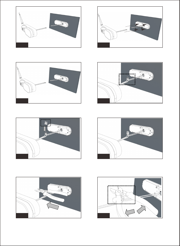
Figure1:
Select a suitable mounting position and drill a center hole on
the vehicle wall.
Figure2:
For prewired trailer and fifthwheel, plug the 3.5mm to DC power cable.
For unprewired trailer and fifthwheel, wire the DC to 2P cable with the
vehicle circuit. Ensure correct polarity when wiring the cables.
Red + Black
Figure3/Figure4: Feed the supplied power cable through gasket.
Ensure the bare end of the cable goes into the vehicle and the flat side
faces inward.
Fig.2Fig.1
Fig.4Fig.3
-8-
CA116 Installation

Figure5/Figure6/Figure7:
Fix the gasket and bracket to the vehicle Figure8, make sure the
power cable is not wrapped or extruded.
Figure8/Figure9/Figure10:
Make sure the sealing lip around the edge of the gasket is seated over
the edge of bracket before fully tightening the provided screws.
Fig.6Fig.5
Fig.8Fig.7
Fig.10Fig.9
Fig.12Fig.11
-9-

Figure11/Figure12/Figure13/Figure14: Pull out the power cable.
Connect the 3.5mm to DC power cable. Connect the power cable to
camera cable.
Figure17/Figure18: Secure the camera on bracket housing with
provided screws. Make sure the connections and the camera
antenna are secured tightly.
Fig.14Fig.13
Fig.16Fig.15
Fig.18Fig.17
-10-

Figure1/Figure2: Remove LED From vehicle by straight screwdriver
Figure5/Figure6: Cutting the cables by a plier and stripping the cables
to expose the conductive core
Fig.2Fig.1
Fig.4Fig.3
Figure1/Figure2: Remove LED From vehicle by straight screwdriver
Fig.6Fig.5
-11-
CA116 Installation without drilling holes

Figure7/Figure8: Ensure correct polarity when wiring the cables.
Red + Black -
Figure11/Figure12/Figure13: Wire connections and terminals must
be sealed securely and waterproof.
Fig.8Fig.7
Fig.10Fig.9
Figure9/Figure10: Clamp the terminal tightly to make sure they are
sealed and waterproof.
Fig.12Fig.11
Fig.13
-12-

Fig.15Fig.14
Fig.17Fig.16
Figure14/Figure15/Figure16: Take out the base from bracket housing.
Fig.19Fig.18
Fig.20 Fig.21
Figure17/Figure18: Insert magnet into base
-13-

Fig.25Fig.24
Figure19/Figure20/Figure21/Figure22: Lock the magnet with bracket
by torx screw.
Fig.27Fig.26
Fig.28 Fig.29
Figure25/Figure26: Remove the hole shield on the bracket base.
Pull cables through the hole.
Fig.23Fig.22
Figure23/Figure24: Connect the power cable to the camera cable.
Bend the cable and tuck it into bracket housing.
Figure27/Figure28: Secure the bracket housing and base with four
provided screws.
-14-

Fig.33Fig.32
Fig.35Fig.34
Fig.36
Fig.31Fig.30
Figure31/Figure32/Figure33/Figure34/Figure35/Figure36:
Remove the protector of metal plate and 3M tape.
-15-

Fig.40Fig.39
Fig.42Fig.41
Fig.43
Figure37/Figure38: Stick the metal plate on flat surface of vehicle
Fig.38Fig.37
Figure43/Figure44: Replace the cover of LED. Installation done.
Fig.44
Figure39/Figure40/Figure41: Adsorb the camera on metal plate
Figure42: Put the LED back and secure it with screws.
-16-

When connecting wires, ensure the circuit is isolated by disconnecting
the negative terminal on the battery.
Ensure correct polarity when wiring the cables. RED + BLACK -.
Wire connections and terminals must be sealed and waterproof.
Warning
The haloview camera system can be connect to an electrical power source
via a 7 way connector
Wiring to running lights:
the camera will active when the running lights are switched on.
Wiring to reverse lights:
the camera will active when the vehicle engages reverse gear.
Consult the vehicle’s service manual for
specific wiring color code.
When wiring this camera directly to a 12V battery or converter in your RV,
use an in-line switch on the power cable to power on or off your camera.
This will enable this camera to be used when parked without a tow vehicle
connected.
Connects to
12V/24V
Power Supply
Connects to
Camera
Running
Reverse or
Auxillary
Lights
ON/OFF + -
DC POWER SUPPLY
-17-
Connecting the Camera

Care and Cleaning
Though your monitor requires little care,you will still need to
maintain its condition and performance by following the
guidelines below.
Keep your system away from excessive moisture,
extreme heat or cold.
Keep liquids away from the display.
Occasionally clean the surface of the monitor with a
soft cloth moistened with water or glass cleaner.
Only clean the unit with a dry cloth. Do not clean the unit with
strong chemical agents or
abrasive cleaners. Never spill liquid of any kind on the
product. Do not allow residue or liquids to enter any part of
the appliance as this may cause rist of electrocution.
Always disconnect from the mains before cleaning.
CAUTION: Never use solvents such as benzene, thinner or
cleaners avaitable commercially to clean the system.
Route the power cable to the vehicle’s 12/24V running light.
The cable must not interfere with the safe operation of the
vehicle.
-18-
Connecting the Traffic Light
This manual suits for next models
2
Table of contents
Other Haloview Automobile Accessories manuals