PAGE4
RC8AQ*A RC12AQ*A
97884C (Rev. A - 3/06)
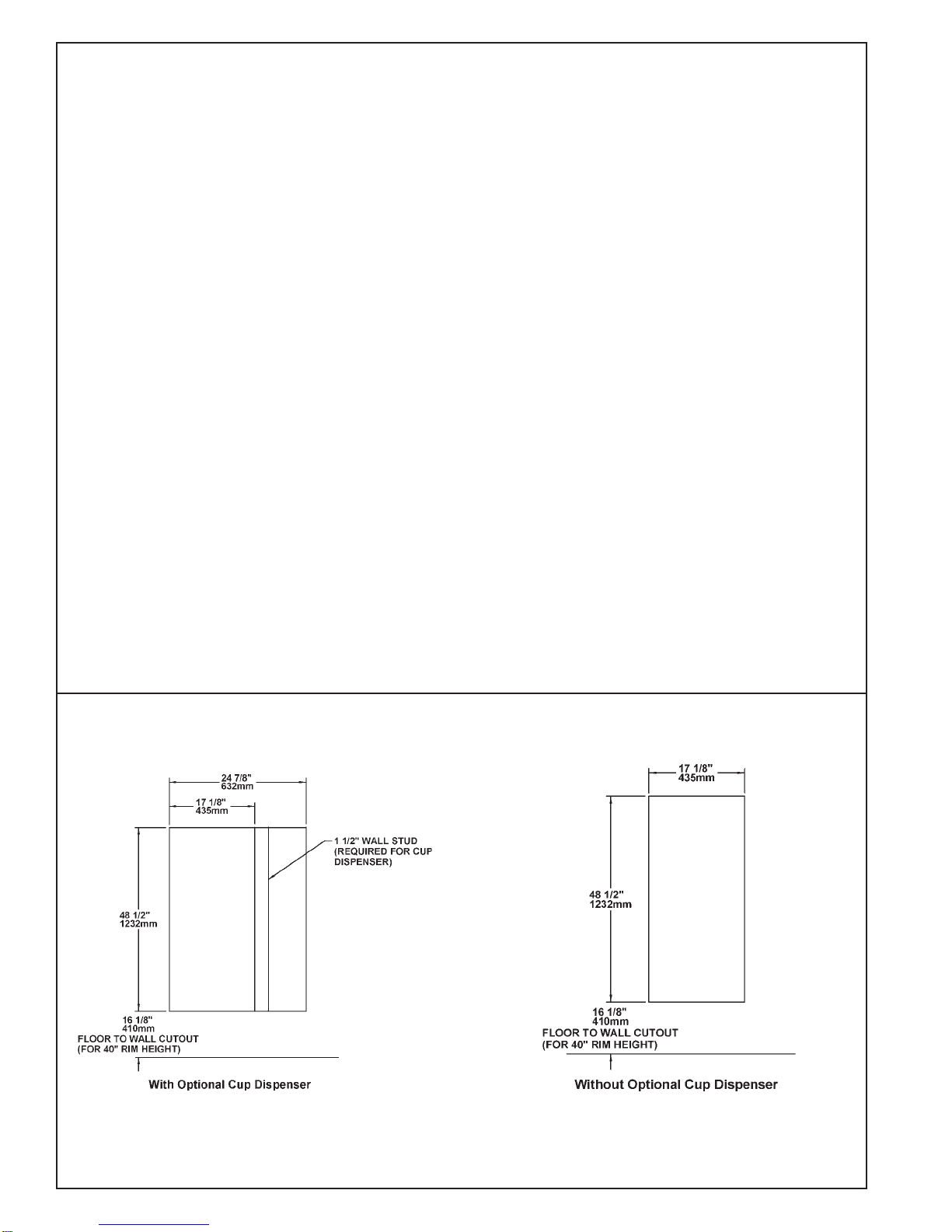
1. Familiarize yourself with the RC Wallframe which should already be in place in the wall. If not, refer to the
“RC Wallframe” Installation Instructions before proceeding.
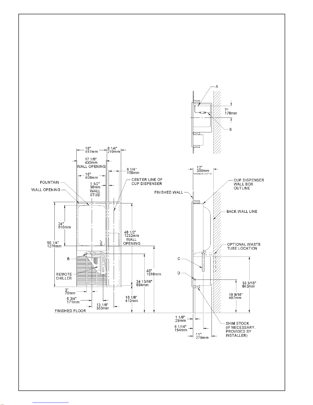
2. Determine location of rough plumbing. At this point, you should decide which style trap you plan to use. For
easier installation, we recommend the use of a swivel trap.
3. Install the basin (See Fig. 7). Hold the basin flush against the wall, positioning the top edge just above the upper
edge of the wallframe. Then slide the basin down slowly until it engages the hanger bracket. Be sure the basin is
firmly engaged before releasing it.
4. Finish securing basin in place. Align the brackets at the bottom of the basin with the bracket on the frame. Fasten
the brackets together using screws and speednuts (provided with fountain).
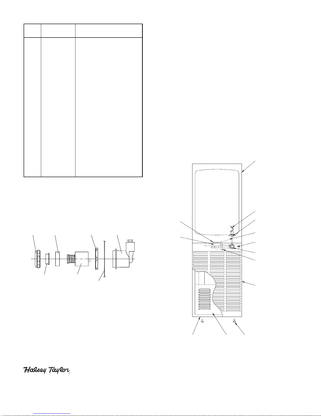
5. Install tailpiece assembly. Slide the slip nut and gasket from the trap onto the tailpiece. Insert the tailpiece
assembly into the trap and align its other end with the drain hole in the basin. Place rubber gasket between the
tailpiece assembly and the basin, then screw in the drain plug from above. Tighten the drain plug. Tighten slip
nut and swivel joint. Snap the strainer plate into the drain plug.
6. Install a service stop (not provided) on the supply water inlet line. Turn on supply water and flush thoroughly.
7. Install refrigeration unit. Slide refrigeration unit into the wallframe and position tight against left side and flush
with the front edge of wallframe. WARNING: Adequate space must be maintained behind the refrigeration unit for
air circulation.
8. Water supply connections (See Figs. 8, 9, & 10)
RC8A Models – Make connections between remote chiller and building supply line. Inlet port is marked on the
chiller (1/4” O.D. copper tube). Bend the copper tube (provided) at an appropriate length from chiller to opening in
frame. Install the in-line strainer (provided with chiller) by pushing it in until it reaches a positive stop, approxi-
mately 3/4” (19mm) on the marked chiller inlet port. Connect building supply line to strainer. DO NOT SOLDER
TUBESINSERTED INTO THESTRAINERASDAMAGETOTHE O-RINGSMAYRESULT.(SeeFig.8)
Make connections between remote chiller outlet tube and fountain. Outlet port is marked on the chiller (1/4”O.D.
copper tube). Install a 1/4” x 1/4” union (provided) on the marked chiller outlet port. Insert the 1/4” poly tubing
coming from the fountain into the union. Turn on the water supply and check for leaks. DO NOT SOLDER
TUBESINSERTED INTO THEUNIONASDAMAGETOTHE O-RINGSMAYRESULT.(SeeFig.8)
RC12A Models – Make connections between precooler and building supply line. Install the in-line strainer
(provided with chiller) by pushing it in until it reaches a positive stop, approximately 3/4” (19mm) on the precooler
inlettube.Connect buildingsupplyline to strainer.DO NOT SOLDER TUBES INSERTED INTO THE STRAINER AS
DAMAGETO THEO-RINGSMAYRESULT. (SeeFig.10)
Make connections between precooler and remote chiller. Inlet port is marked on the chiller (1/4” O.D. copper
tube). Bend the copper tube (provided) at an appropriate length from chiller and install a 1/4” x 3/8” union (pro-
vided) on the marked chiller inlet port. Insert the precooler outlet tube into the union. DO NOT SOLDER TUBES
INSERTEDINTOTHE UNIONAS DAMAGETOTHEO-RINGS MAYRESULT. (SeeFig.10)
Make connections between remote chiller outlet tube and fountain. Outlet port is marked on the chiller (1/4”O.D.
copper tube). Install a 1/4” x 1/4” union (provided) on the marked chiller outlet port. Insert the 1/4” poly tubing
coming from the fountain into the union. Turn on the water supply and check for leaks. DO NOT SOLDER
TUBESINSERTED INTO THEUNIONASDAMAGETOTHE O-RINGSMAYRESULT.(SeeFig.10)
9. GF Model Only. Make connections between remote chiller outlet tube and fountain. Outlet port is marked on the
chiller (1/4” O.D. copper tube). Install a 1/4” x 1/4” tee (provided) on the marked chiller outlet port. Insert the 1/4”
poly tubing coming from the fountain into the tee. Connect glass filler line to outlet on tee. Install a 1/4” x 3/8” union
(provided) on the glass filler outlet line. Insert a piece of 1/4” poly tubing from the tee to the union. Turn on the
watersupply andcheck forleaks. DONOTSOLDERTUBESINSERTEDINTO THEUNION/TEE ASDAMAGE TOTHE
O-RINGS MAY RESULT. (SeeFig. 9)
10. Open service stop and operate push button to purge air. Check thoroughly for leaks.
INSTALLATION INSTRUCTIONS
FORTHE
RC MODELS DRINKING FOUNTAIN
(refrigeratedandnon-refrigerated)