Page 3 of 26
7020-969-001 Revised: 12/11/2018
MURDOCK MFG. • 15125 Proctor Avenue • City of Industry, CA 91746 USA
Phone 800-453-7465 or 626-333-2543 • Fax 626-855-4860 • www.murdockmfg.com Member of
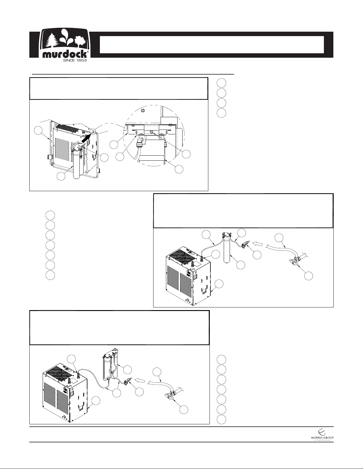
I N S TA L L AT I O N / M A I N T E N A N C E I N S T R U C T I O N S
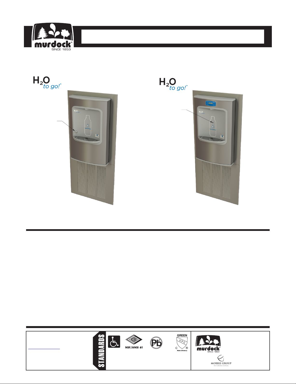
Surface Mounted Bottle Fillers
6. Electrical Receptacle(s) must be wired to a GFCI protected circuit. Fixture must be earth grounded per NEC
(National Electrical Code).
4. Provide rough-ins as shown on the roughing-in and dimensional drawing, including water supply, drain pipe
and gravel drain well. (See rough-in details)
5. It is common for electrical equipment to be grounded to water lines either within a structure or away; otherwise,
remains unchanged by the materials in the water cooler. Every attempt should be made to prevent this kind of
grounding from generating feedback into the water cooler creating electrolysis. Electrolysis will cause a
metallic taste or cause water metal content to increase.
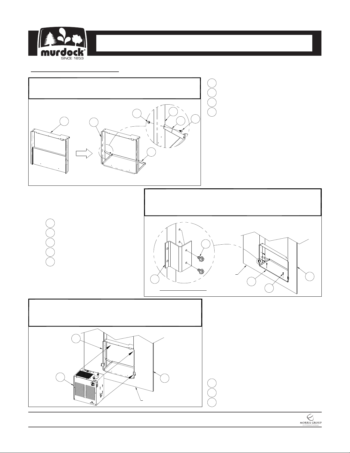
3. Provide mounting surface, adequate to support the fixture and loads on the fixture.
7. Completely flush water supply lines of all foreign debris, before connecting to the fixture.
2. Carefully remove all fixture components from packaging, preventing scratching or damage. Inspect fixture and
all parts from damages and all parts that are bolted on.
1. Read all installation instructions carefully, before proceeding.
2. Provide 4” minimum clear space in front of Bottom Trim Panel and above In-Wall Chiller to allow for proper
ventilation.
9. WARNING: Warranty is void if installation is not made following current Murdock Mfg. installation instructions
and if components are assembled to the fixture that are not approved by Murdock Mfg.
4. Completely flush supply lines of all foreign debris before connecting to fixture. A dielectric coupler must be
used to connect the drinking fountain to the water supply. A non-metallic coupler is furnished with this unit to
make this ROP. Water cooler designed to not cause problems with taste, odor, color, or sediment. Optional
Water Filter, is available should any of these problems arise from the water supply.
8. This unit must be grounded per the requirements of applicable electrical codes.
IMPORTANT:
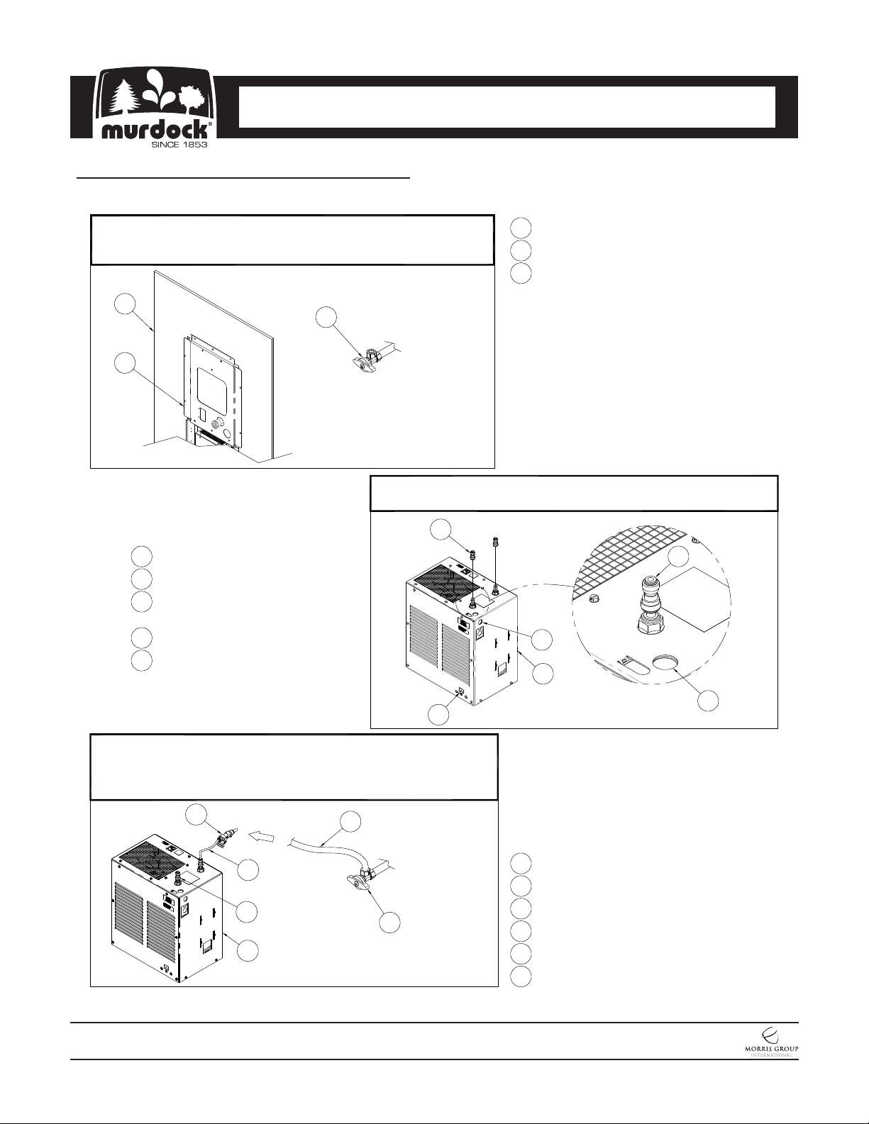
3. Waste is 1-1/4” Outer Diameter. Chiller water inlet is 3/8” Outer Diameter copper tube. Chiller water outlet is
3/8” Outer Diameter copper tube. Drinking Fountain water inlet is 3/8” Outer Diameter copper tube. Bottle
Filler water inlet is 3/8” Outer Diameter copper tube. Water line from in-wall chiller to drinking fountain must
have adequate insulation, provided by installer.
5. Do NOT solder Tubes inserted into the Chiller or Bottle Filler as damage to the O-Rings on the Push-In
Fittings may result.
6. All burrs must be removed from outside of cut tubes before inserting into strainer or other components.
7. Power supply must be identical in voltage, cycle and phase to that specified on the chiller data plate. Refer to
submittal.
1. Water Supply Service Stop Valve, Water Connections and Electrical Connections to be supplied by others in
accordance with local codes.
10. Fixture operates within water pressure range of 25 PSIG (174 kPa) to 105 PSIG (724 kPa). Murdock Mfg. will
not warranty chiller damaged when connected to supply lines with flow pressure lower than 25 PSIG (174
kPa) or higher than 105 PSIG (724 kPa). A pressure regulator must be furnished by others on supply line if
inlet pressure is greater than 105 PSIG (724 kPa). 40-60 PSI is recommended.
11. Due to cold waste water, Murdock Mfg. recommends that waste piping supplied by installer be insulated
appropriately to prevent excessive condensation.
12. Per UPC 609.10-All building water supply systems in which quick acting valves are installed shall be
provided with devices to absorb the hammer caused by high pressure resulting from the quick closing of the
valve. These pressure-absorbing devices shall be approved mechanical devices. Water pressure-absorbing
devices shall be installed as close as possible to the quick closing valve
PRIOR TO INSTALLATION: