14 15
At Haltech we make every eort to design and
manufacture fault-free products that perform up to
or above the market expectations. All our products
are covered by a Limited 12 Month Warranty.
Haltech Limited Warranty
Unless specied otherwise, Haltech warrants its products
to be free from defects in material or workmanship for a
period of 12 months from the date of purchase.
If the Haltech product is found to be defective as men-
tioned above, it will be replaced or repaired if returned
prepaid along with proof of purchase. Proof of purchase
in the form of a copy of the original purchase invoice,
receipt or bill of sale which indicates that the product is
within the warranty period, must be presented to obtain
warranty service.
Replacement or repair of a defective product shall con-
stitute the sole liability of Haltech. To the extent permitted
by law, the foregoing is exclusive and in lieu of all other
warranties or representations, either expressed or im-
plied, including any implied warranty of merchantability
or tness. In no event shall Haltech, be liable for special
or consequential damages.
Product Returns
Please include a copy of the original purchase invoice,
receipt or bill of sale along with the unused, undamaged
product and its original packaging. Any product returned
with missing accessory items or packaging will incur ex-
tra charges to return the item to a re-saleable condition.
All product returns must be sent via a freight method
with adequate tracking, insurance and proof of delivery
services. Haltech will not be held responsible for product
returns lost during transit.
Returns of Products Supplied in Sealed
Packaging
The sale of any sensor or accessory supplied in sealed
packaging is strictly non-refundable if the sealed pack-
aging has been opened or tampered with. This will be
clearly noted on the product packaging. If you do not ac-
cept these terms please return the sensor in its original
unopened packaging within 30 days for a full refund.
A sensor or accessory product may be returned after 30
days of purchase (with its sealed packaging intact) for
credit only (no refunds given) and will be subject to a 10%
restocking fee.
Installation of Haltech Products
No responsibility whatsoever is accepted by Haltech for
the tment of Haltech Products. The onus is clearly on
the installer to ensure that both their knowledge and the
parts selected are correct for that particular application.
Any damage to parts or consequential damage or costs
resulting from the incorrect installation of Haltech prod-
ucts are totally the responsibility of the installer.
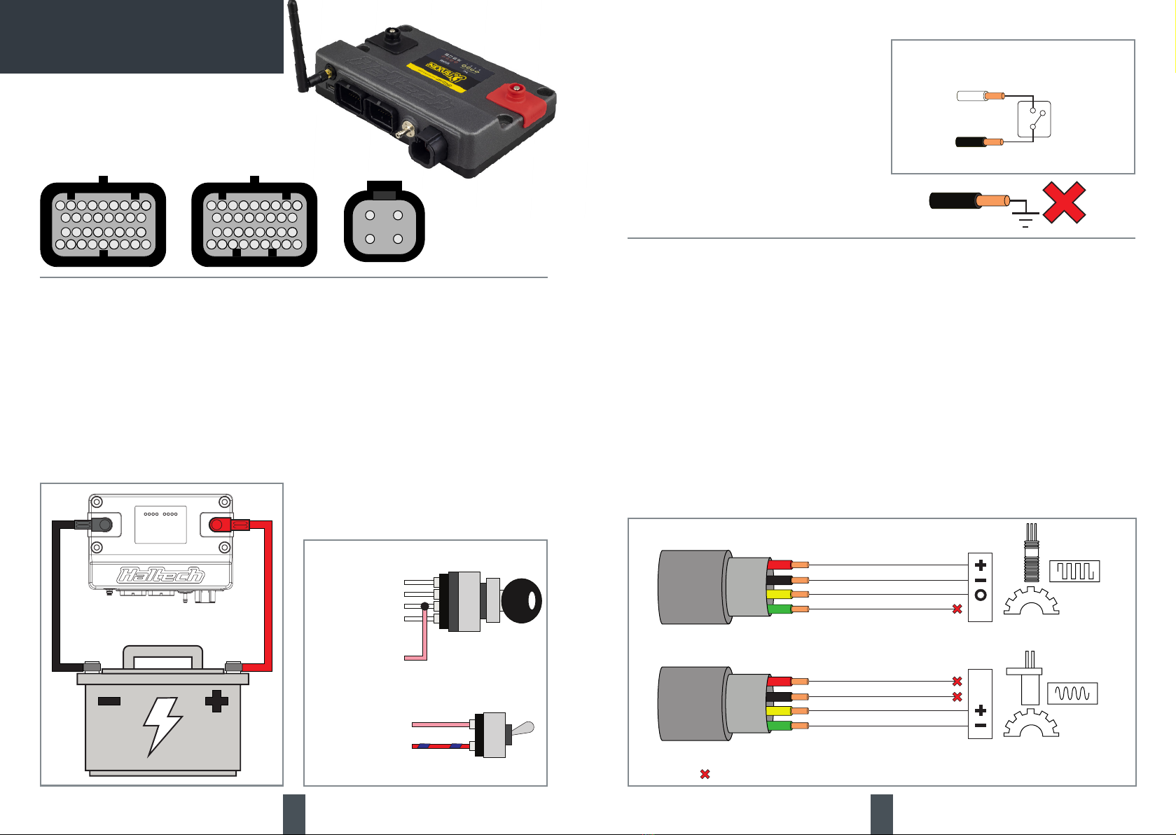
Always disconnect the battery when doing electrical
work on your vehicle. Avoid sparks, open ames or use
of electrical devices near ammable substances. Do not
run the engine with a battery charger connected as this
could damage the ECU and other electrical equipment.
Do not overcharge the battery or reverse the polarity of
the battery or any charging unit. Disconnect the Haltech
ECU from the electrical system whenever doing any
welding on the vehicle by unplugging the wiring harness
connector from the ECU.
After completing the ECU installation, make sure there is
no wiring left un-insulated. Uninsulated wiring can cause
sparks, short circuits and in some cases re. Before at-
tempting to run the engine ensure there are no leaks in
the fuel system.
All fuel system components and wiring should be mount-
ed away from heat sources, shielded if necessary and
well ventilated. Always ensure that you follow work-
shop safety procedures. If you’re working underneath a
jacked-up car, always use safety stands!
_____________________________________________
Haltech O-Road Usage Policy
In many states it is unlawful to tamper with your vehicle’s
emissions equipment. Haltech products are designed
and sold for sanctioned o-road/competition non-emis-
sions controlled vehicles only and may never be used on
a public road or highway.
Using Haltech products for street/road use on public
roads or highways is prohibited by law unless a specif-
ic regulatory exemption exists (more information can be
found on the SEMA Action Network website www.sema-
san.com/emissions for state by state details in the USA).
It is the responsibility of the installer and/or user of this
product to ensure compliance with all applicable local
and federal laws and regulations. Please check with your
local vehicle authority before purchasing, using or install-
ing any Haltech product.
WARRANTY CERTIFICATE
WIRING NOTES
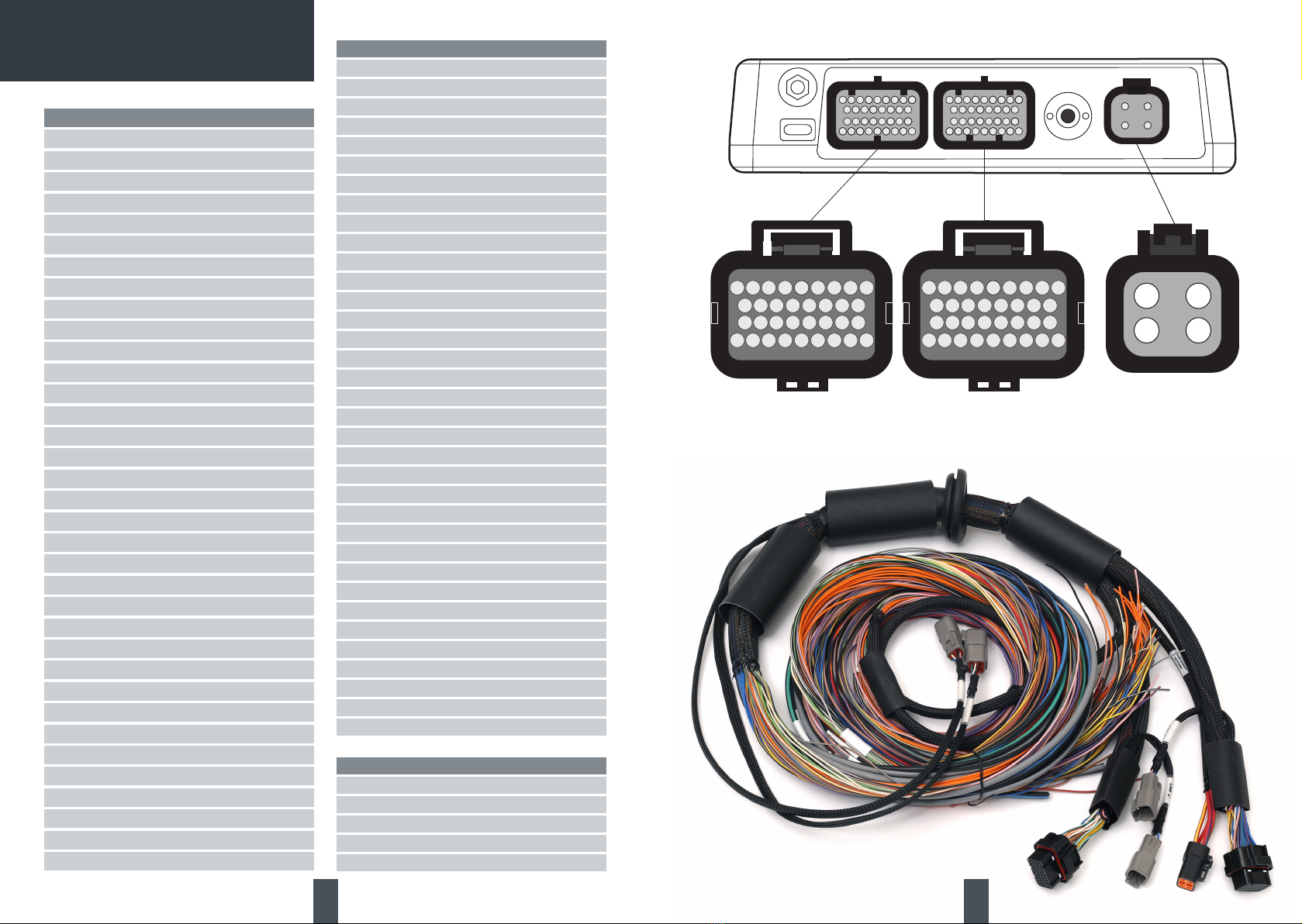
CONNECTOR A
Pin Function Colour Notes
A1 INJ 1 Blue _______________
A2 INJ 2 Blue/Black _______________
A3 INJ 3 Blue/Brown _______________
A4 INJ 4 Blue/Red _______________
A5 INJ 5 Blue/Orange _______________
A6 INJ 6 Blue/Yellow _______________
A7 INJ 7 Blue/Green _______________
A8 INJ 8 Blue/Violet _______________
A9 DPO 1 Violet/Black _______________
A10 PGND OUT Black _______________
A11 PGND OUT Black _______________
A12 DPO 2 Violet/Brown _______________
A13 IGN SW IN Pink _______________
A14 DPO 3 Violet/Red _______________
A15 DPO 4 Violet/Orange _______________
A16 DPO 5 Violet/Yellow _______________
A17 DPO 6 Violet/Green _______________
A18 HBO5 (12V) Pink/Red _______________
A19 HBO 1 Brown/Black _______________
A20 HBO 2 Brown/Red _______________
A21 HBO 3 Brown/Green _______________
A22 HBO 4 Brown/Pink _______________
A23 CAN1H White _______________
A24 CAN1L Blue _______________
A25 HBO6(12V) Pink/Brown _______________
A26 +12V LOW Red/Blue _______________
A27 IGN 1 Yellow/Black _______________
A28 IGN 2 Yellow/Red _______________
A29 IGN 3 Yellow/Orange _______________
A30 IGN 4 Yellow/Green _______________
A31 IGN 5 Yellow/Brown _______________
A32 IGN 6 Yellow/Blue _______________
A33 IGN 7 Yellow/Violet _______________
A34 IGN 8 Yellow/Gray _______________
Notes:
CONNECTOR C
Pin Function Colour Notes
C1 TRIG+ Yellow ______________
C2 TRIG - Green ______________
C3 HOME + Yellow ______________
C4 HOME - Green ______________
C5 SPI 1 Gray/Brown ______________
C6 SPI 2 Gray/Red ______________
C7 SPI 3 Gray/Orange ______________
C8 SPI 4 Gray/Yellow ______________
C9 +8V Orange/White ______________
C10 AVI 1 White ______________
C11 AVI 2 White/Yellow ______________
C12 AVI 3 White/Gray ______________
C13 AVI 4 White/Violet ______________
C14 AVI 5 White/Green ______________
C15 AVI 6 White/Orange ______________
C16 AVI 7 White/Black ______________
C17 AVI 8 White/Brown ______________
C18 AVI 9 White/Red ______________
C19 SPI 5 Gray/Pink ______________
C20 SPI 6 Gray/L.Green ______________
C21 CAN2H White ______________
C22 CAN2L Blue ______________
C23 Knock 1 Black/Blue ______________
C24 Knock 2 Black/Green ______________
C25 +5V Orange ______________
C26 SGND A Black/White ______________
C27 AVI 10 L.Green ______________
C28 AVI 11 L.Green/Black ______________
C29 WB Heater+ Gray ______________
C30 WB Input Yellow ______________
C31 WB Pump Red ______________
C32 WB Nernst Black ______________
C33 WB Heater- White ______________
C34 WB Cal Green ______________
Notes:
CONNECTOR E
Pin Function Colour Notes
E1 INJ 12V Red/Blue ______________
E2 IGN 12V Red/Yellow ______________
E3 25A-HCO 3 Red/Orange ______________
E4 25A-HCO 4 Red/Green ______________
Notes: