Hamamatsu Photonics EX-mini L12530 User manual

Read this user’s manual carefully before attempting to operate or service
this product.
Do not attempt to operate or service this product until you completely
understand the contents of this manual.
Those responsible for this product should not allow personnel to operate or
service it unless they thoroughly understand this manual.
Keep this manual near the product for easy reference when needed.
If this manual is lost or damaged, promptly order a replacement copy from
our sales office or sales representative.
If transferring this product to another party, make sure that this manual is
included along with the product.
The contents of this manual are subject to change without prior notice due
to product improvement.
Reproduction or copying of this manual in part or in whole is prohibited
without the permission of Hamamatsu Photonics.
USER’S MANUAL
Compact Excimer Lamp Light Source
EX
-
mini
L1
2530
@W2-0245-1

2
Table of contents
1. Safety precautions................................................................................................ 3
1-1 Warning symbols and signal words...................................................................... 3
1-2 Precautions.......................................................................................................... 4
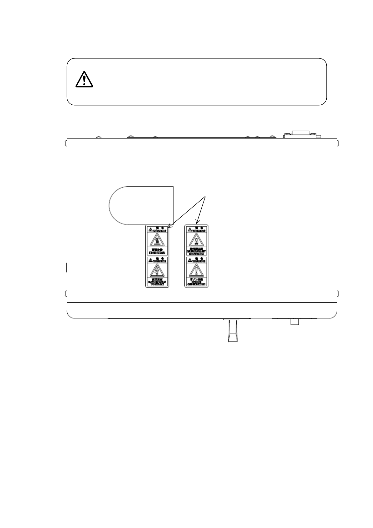
1-3 Warning label position.......................................................................................... 7
2. Product overview.................................................................................................. 8
3. Package contents ................................................................................................. 8
4. Product specifications........................................................................................... 8
4-1 General ratings .................................................................................................... 8
4-2 Optical characteristics.......................................................................................... 8
5. Part names and functions..................................................................................... 9
5-1 Front panel........................................................................................................... 9
5-2 Rear panel......................................................................................................... 10
5-3 Side panels.........................................................................................................11
5-4 Sample chamber................................................................................................ 12
6. Making the connections...................................................................................... 13
6-1 Connecting an exhaust duct .............................................................................. 13
6-2 Connecting the power cable .............................................................................. 13
6-3 Connecting an air tube to the gas inlet port ....................................................... 13
7. How to use.......................................................................................................... 14
7-1 Pre-operation check........................................................................................... 14
7-2 Operation........................................................................................................... 14
7-3 Turning off the unit............................................................................................. 15
7-4 Replacing the lamp............................................................................................ 15
7-5 External control.................................................................................................. 16
7-6 Alarms and errors .............................................................................................. 18
7-7 Precautions during use...................................................................................... 18
8. Maintenance and inspection............................................................................... 19
9. Troubleshooting.................................................................................................. 19
10. Warranty and after-sales service...................................................................... 200
10-1 Warranty .......................................................................................................... 200
10-2 After-sales service ........................................................................................... 200
11. Dimensional outlines......................................................................................... 211
If any of the following problems are found, please contact our sales office then we
can quickly take corrective measures
When omissions, errors or dubious points are found in the text of this manual
When problems such as the wrong page order or missing pages are found
When this manual was lost, soiled or damaged

3
1. Safety precautions
1-1 Warning symbols and signal words
Warning symbols and signal words used in this manual and product are classified as explained
below. Make sure that you fully understand the meaning of each symbol and comply with the
instructions.
WARNING "WARNING" indicates a potentially hazardous situation which,
if not avoided, could result in death or serious injury.
CAUTION "CAUTION" indicates a potentially hazardous situation which,
if not avoided, could result in minor or moderate injury or
damage to the equipment.
This symbol indicates a precaution you must take. Read the
instructions carefully to ensure correct and safe product use.
This symbol indicates a prohibited action. Read the
instructions carefully and never attempt the prohibited action.
This symbol indicates a mandatory action. Read the
instructions carefully and always use the specified procedure.
Gives precautions or key points for extracting the full
performance from this product. Read the instructions carefully
to ensure correct and safe product use. Failure to follow the
instructions may result in poor performance.
Before using this product, be sure to read the safety precautions in this section
carefully and comply with the instructions.
NOTE

4
1-2 Precautions
To use this product safely and correctly, always comply with the safety precautions and
instructions described in this manual. Using this product in ways not specified in this manual may
impair the protective functions of this product. Breakdowns or problems caused by failing to
observe these precautions are not covered by our warranty.
●Do not disassemble or modify this unit.
Do not remove or open the cover. Do not disassemble or modify the unit.
Doing so may cause fire, electrical shock or injury.
The internal electronic components are precisely adjusted. Touching them may impair
the adjustment, making it impossible to maintain the required performance.
※When internal inspection or repair is necessary, contact our sales office.
●Power supply
This unit must be grounded properly. (Connect the unit to a grounded AC
power outlet.)
●Emitted light
This unit emits intense UV light harmful to the eyes and skin. The UV light emission
also causes ozone to form. Observe the following instructions during operation.
Always wear safety glasses, gloves, and other appropriate protective gear
when operating this unit. (Refer to JIS T8141 or equivalent standards.)
If the lamp bursts, the glass fragments may cause injury.
When light is emitted in an atmosphere containing oxygen (such as room
air), the area must be well ventilated since ozone harmful to the human body
will form.
Inhaling ozone may cause headaches, nausea, or dizziness.
●When turning on the lamp
Never turn on the lamp while the case is open.
High-frequency (radio-frequency) AC voltage of several thousand volts is generated by
the transformer during operation.
Turning on the lamp while the case is open may cause fire or electrical shock.
●If an abnormality occurs…
If smoke, unusual odor or noise is emitted from the unit, immediately turn off
the MAIN switch on this unit and then unplug the power cable.
Continuous operation under such abnormal conditions may cause fire or electrical
shock.
●Do not damage the power cable.
A damaged or worn power cable may cause fire or electrical shock.
・Do not modify or damage the power cable.
・Do not heat the power cable or place the power cable close to a heater.
・Do not place a heavy object on the power cable.
・Do not pull on the power cable when unplugging it.
WARNING

5
●Do not allow water, liquid or foreign matter to enter the unit.
Water or foreign matter may cause fire or electrical shock.
※If water or foreign matter has entered the unit, immediately stop using it and
consult our sales office or representative for correct servicing.
●Do not touch the unit with wet hands.
Touching it with wet hands may cause electrical shock.
Use extreme caution when handling this unit.
The lamp contained in this unit is made of glass. The mechanical components of this unit
are precisely adjusted.
Excessive vibration and shock may damage the lamp or impair the adjustment, causing
fire or electrical shock.
Do not cover this unit with paper or cloth, and do not place flammable
materials near it.
Doing so may cause fire.
Do not touch this unit during operation or immediately after operation.
The section around the lamp is very hot during operation or immediately after operation.
Touching it may cause burns.
If the lamp is cracked, stop using it.
Operating a cracked lamp may cause electric shock, etc.
Do not use this unit in an atmosphere where flammable materials such as
thinner are present.
Using this unit in a flammable atmosphere may cause explosion or fire.
Do not use this unit in a corrosive atmosphere or in locations subject to
excessive dust.
Using this unit in such locations may cause electrical leakage or overheating.
Do not touch the lamp with bare hands.
If organic matter or decomposed matter adheres to the outer surface of the lamp, the
output intensity may drop.
Replace the lamp when the total lamp ON time has exceeded 1000 hours.
When the total lamp ON time has exceeded 1000 hours, a “forced stop error” occurs and
prevents the lamp from lighting up. In this case, please return the unit to us since we will
replace the lamp with a new one.
CAUTION

6
●Disposal
Power supply and housing
When disposing of this product, take appropriate measures in compliance with
applicable regulations regarding waste disposal and correctly dispose of it yourself, or
entrust proper disposal to a licensed industrial waste disposal company. In any case, be
sure to comply with the regulations in your country or state to ensure correct disposal.
Lamp
The lamp used in this product is filled with xenon gas. When disposing of this product,
take appropriate measures in compliance with applicable regulations regarding waste
disposal and correctly dispose of it yourself, or entrust proper disposal to a licensed
industrial waste disposal company. In any case, be sure to comply with the regulations
in your country or state to ensure correct disposal.
■This product uses the following symbol marks
"CAUTION" - This label is affixed to the product to indicate a
position where you must refer to the user's manual or service
manual to protect personnel and equipment.
AC (alternating current)
ON (power)
OFF (power)

7
1-3 Warning label position
The warning labels affixed to the unit must be clearly visible at all times.
If the label peels off or becomes dirty, replace it with a new label.
Please contact our sales office for a replacement warning label
(available for a charge).
●Top view
High temperature, high voltage, UV light emission,
ozone generation warning labels

8
2. Product overview
This product is a UV irradiation light source using a flat type xenon excimer lamp that emits UV light at a
center wavelength of 172 nm in high-frequency (radio frequency) lighting mode.
3. Package contents
After unpacking, make sure the following items are included.
・Compact excimer lamp light source........ 1
・Power cable ............................................ 1 (2 meters)
・User’s manual......................................... 1 (this manual)
・Shorting connector for external fan......... 1
・External control connector...................... 1
4. Product specifications
4-1 General ratings
Power requirement (AC)............................. 100 V to 240 V
Power frequency......................................... Single phase 50 Hz / 60 Hz
Lighting frequency ...................................... 1.7 MHz ±0.2 MHz
Power consumption.................................... 130 VA or less
Cooling method........................................... Forced air cooling (exhaust air flow rate: 0.25 to 0.35
m3per minute) using duct (should be installed by
users) or by ozone decomposition unit E12685 (sold
separately)
External dimensions ................................... 344 mm (W) × 230 mm (D) × 233 mm (H)
(not including projecting parts)
Sample chamber dimensions..................... 204 (W) × 139 (D) × 118 (H)
(not including projecting parts)
Weight......................................................... Approx. 7.0 kg
Operating temperature
(around light source)................................. +5 °C to +35 °C (no condensation)
Operating humidity...................................... 80 % or less (no condensation)
Location for use.......................................... Indoor use
Altitude for use............................................ Up to 2000 m
Overvoltage category.................................. Ⅱ
Pollution degree.......................................... 2
IP code........................................................ IP20
4-2 Optical characteristics
Irradiance.................................................... 50 mW/cm2 or more (Initial irradiance measured with
Hamamatsu UV power meter H8025-172 while its
sensor head is directly made contact with lamp
surface)
Guaranteed lamp life .................................. 500 hours
Lamp replacement life ................................ 1000 hours (Time at which irradiance drops to 70 %
of initial value or lamp won’t light up)
Peak wavelength ........................................ 172 nm (Spectral half-width: 17 nm)
Time taken for light intensity to stabilize..... Within 10 minutes
Emission area............................................. 86 mm × 40 mm
Effective emission area............................... 75 mm × 30 mm (Area where irradiance is higher
than 50 mW/cm2)

9
5. Part names and functions
5-1 Front panel
①Display panel Displays irradiation time, total lamp ON time, errors, etc.
②Error display Flashes when an error occurs.
③MENU button Use to switch between display units and digit for irradiation time
setting.
④DOWN button Use to change the time or units for irradiation time setting.
⑤UP button Use to change the time or units for irradiation time setting.
⑥MODE button Use to select irradiation mode. (Button is lit inAUTO mode.)
⑦ON/OFF button Use to turn the lamp on or off. (Button is lit when the lamp is lit.)
⑧POWER switch Pressing the “I” side of this switch turns on power.
⑨Duct connection port Connect this port to a local exhaust ventilation system or an ozone
decomposition unit E12685 (sold separately), and exhaust the
internal air at an airflow rate of 0.25 to 0.35 m3per minute.
⑩Sample chamber door Door for inserting or removing a sample. The lamp won’t light up
when this door is open.
①
②
③
④
⑤
⑥
⑦
⑧
⑩
⑨

10
5-2 Rear panel
①EXT. FAN
(external fan connector) Use this connector when connecting to an ozone
decomposition unit E12685 (sold separately). When not using
the ozone decomposition unit, always plug the supplied
shorting connector for external fan into this connector.
②EXT. CONTROL
(external control connector) When using an external control unit, connect it to this connector
using the supplied external control connector.
③AC INPUT Connect the supplied power cable to this connector.
④Name label Shows the model name, serial number, etc.
②
③
①④

11
5-3 Side panels
①Cooling fan air intake vents Air intake vents for cooling the internal power supply. When
installing this unit, provide a space of at least 10 cm from these
vents to a wall or other objects.
②Air exhaust vents Air exhaust vents for cooling the internal power supply. When
installing this unit, provide a space of at least 10 cm from these
vents to a wall or other objects.
③Gas inlet port Gas can be introduced into the sample chamber by inserting an
air tube (outer diameter: 6 mm) into this port. To introduce gas
into the sample chamber, close the ozone outlet and air vents in
the sample chamber. (NOTE)
Even in that case, always connect a local exhaust ventilation
system or an ozone decomposition unit E12685 (sold
separately) to the duct connection port of this unit.
Never use flammable gases.
NOTE: See section 5-4 “Sample chamber” for details.
③
①②

12
5-4 Sample chamber
①Excimer lamp Excimer lamp main body. The lamp is still very hot shortly after
operation. Before beginning work and touching the lamp, always
wear gloves and make sure the lamp has been cooled down.
②Ozone outlet Vent for exhausting ozone generated in the sample chamber. Do
not block this ozone outlet when used in an atmosphere where
ozone is generated.(Note)
③Ozone outlet cover When introducing external gas into the sample chamber, use this
cover to close the ozone outlet.
④Vent cover When introducing external gas into the sample chamber, use this
cover to close the air vents.
⑤Gas inlet port This port is for introducing external gas into the sample chamber.
⑥Air vents Do not block these air vents when used in an atmosphere where
ozone is generated. (Note)
NOTE: When introducing external gas into the sample chamber, close the ozone outlet and air
vents with the covers. Even in that case, always connect a local exhaust ventilation system or an
ozone decomposition unit E12685 (sold separately) to the duct connection port of this unit.
①
②
⑤
⑥
④
③
When introducing gas into
the sample chamber, use
these covers to close the
ozone outlet and air vents.

13
6. Making the connections
CAUTION
This unit does not include an air exhaust fan. Always connect to a local
exhaust ventilation system or an ozone decomposition unit E12685 (sold
separately), and exhaust the internal air at an airflow rate of 0.25 to 0.35 m3
per minute.
6-1 Connecting an exhaust duct (user’s duct)
Connect a flexible metal duct (inner diameter: 50 mm) to the duct connection port of this unit. Use
a hose band to prevent the duct from disconnecting.
When using an ozone decomposition unit E12685 (sold separately), connect it to the duct
connection port using the hose bands that come with the E12685.
CAUTION
Before connecting the power cable, make sure that the POWER switch on
this unit is OFF.
6-2 Connecting the power cable
Connect the supplied power cable to theAC INPUT connector on the rear of this unit.
Do not use the supplied power cable for any other equipment.
This unit must be grounded to ensure safe use.
6-3 Connecting an air tube to the gas inlet port
Insert an air tube (inner diameter: 6 mm) into the gas inlet port on the side of this unit. Close the
ozone outlet and air vents in the sample chamber and then introduce gas into the sample chamber.
Even in that case, always connect a local exhaust ventilation system or an ozone decomposition
unit E12685 (sold separately) to the duct connection port of this unit. Never use flammable gases.

14
LAMP 0000h
AUTO 010.0s
LAMP 0000h
MANU 000.0s
7. How to use
7-1 Pre-operation check
Check the unit for abnormal condition. Also check that the cables, ducts and tubes are securely
connected.
7-2 Operation
7-2-1 Starting the unit
Turn on the POWER switch on this unit.
The display panel lights up to show the total lamp ON time and operation mode (initial mode is
MANUAL).
Pressing the MODE button entersAUTO mode (The MODE button lights up in AUTO mode).
7-2-2 MANUAL mode
In MANUAL mode, you can manually turn the lamp on and off without setting the irradiation time.
Press the LAMP ON/OFF button to light up the lamp (the LAMP ON/OFF button also lights up
when the lamp is ON.)
After the lamp lights up, the irradiation time on the display panel starts counting up.
To turn off the lamp, press the LAMP ON/OFF button again. (When the lamp is turned off, the
irradiation time until that point remains displayed and will be automatically reset and start counting
up from 0 when lighting up the lamp again.)
Turn on the POWER switch.
The MODE button lights up in AUTO mode.
The LAMP ON/OFF button lights up
when the lamp is lit.

15
LAMP 0000h
AUTO 00h00m
LAMP 0000h
AUTO 0000h
LAMP 0000h
AUTO 010.0s
LAMP 0000h
AUTO 00m10s
7-2-3 AUTO mode
AUTO mode allows you to set the length of irradiation time.After the lamp lights up in AUTO mode,
it automatically turns off when the set irradiation time has elapsed.
In AUTO mode (MODE button is lit up), press and hold the MENU button (for 1 second or longer)
to move to the irradiation time setting screen (initial irradiation time setting is 10 seconds).
Press the UP/DOWN buttons to change the units as needed (seconds →minutes+seconds →
hours+minutes →hours).
Press the MENU button to return to the irradiation time setting screen.
Press the UP/DOWN buttons to set the desired length of irradiation time.
To move to the next digit to set, press the MENU button.
When you have set the irradiation time, press and hold the MENU button for 1 second or more to
finish the setting.
Then press the LAMP ON/OFF button to light up the lamp (the LAMP ON/OFF button also lights up
when the lamp is ON).
After the lamp lights up, the set irradiation time on the display panel starts counting down.
The lamp automatically turns off when the irradiation time on the display panel reaches 0 (zero) or
the LAMP ON/OFF button is pressed again.
7-3 Turning off the unit
Turn off the POWER switch on this unit.
When not using this unit, unplug the power cable from the AC INPUT connector.
7-4 Replacing the lamp
When the total lamp ON time reaches 1000 hours, a “forced stop error” (ERROR: LAMP TIME)
occurs and prevents the lamp from lighting up. (Prior to this error, an “ALARM: LAMP TIME”
message appears on the display panel when the total lamp ON time reaches 900 hours.)
When the lamp needs to be replaced, return the unit to us since we will replace the lamp with a
new one.
Press and hold the MENU button for 1 second or
longer to move to the irradiation time setting screen.
Press the UP/DOWN buttons to change the units.
Press the MENU button to return to the irradiation time setting
screen.
Press the UP/DOWN buttons to set the desired length of
irradiation time
Press the MENU button to move to the next digit to set.
Press and hold the MENU button (for 1 second or more) to finish
the setting.

16
7-5 External control
This unit can be controlled by external control. Use the supplied “external control connector” to
control this unit by external control.
Table 1: Description of external control connector XM2F-1540 (made by OMRON)
Pin No. Signal name IN/OUT Description
1 Manual irradiation (+) IN The lamp lights up as long as pins 1 and 2 are
shorted. (manual irradiation)
2 Manual irradiation (-) -
3 Auto irradiation (+) IN The lamp lights up by shorting pins 3 and 4 for 100
milliseconds or more. When the lamp is lit in AUTO
mode, shorting pins 3 and 4 for 100 milliseconds or
more turns off the lamp.
4 Auto irradiation (-) -
5 Lamp ON signal OUT Outputs a signal (open collector output) as long as
the lamp is lit.
6 Error signal OUT
Outputs a signal (open collector output) when an
error such as a lamp error, lamp lifetime error and
fan error occurs.
7 N.C. - Do not connect.
8 N.C. - Do not connect.
9 +24 OUT
+24 V DC output (100 mA max.)
10 +24 OUT
11 +24 OUT
12 GND -
Ground for external control connection
13 GND -
14 GND -
15 GND -
Connector external view and pinout

17
Control signal output
The load connected to the signal output should be as follows:
Voltage: 30 V or less
Current: 50 mA or less.
Shorting the signal output terminal to the GND terminal outputs a signal.
Control signal input
The ON contact point and transistor rating should be as follows:
Withstand voltage: 30 V or more
Current: 10 mA or more.
Shorting the signal input terminal (+) and the signal input terminal (-) serves as a signal input.

18
7-6 Alarms and errors
7-6-1 Lamp lifetime alarm (ALARM: LAMP TIME)
A “lamp lifetime alarm” occurs when the total lamp ON time reaches 900 hours. The “ALARM:
LAMP TIME” message appears on the display panel and starts flashing. (The unit operates
normally even when this alarm is issued.)
7-6-2 Interlock alarm (ALARM: DOOR OPEN)
An “interlock alarm” occurs when the sample chamber door is opened during operation. The
“ALARM: DOOR OPEN” message appears on the display panel and starts flashing. The lamp will
not light up in this state. If an “interlock alarm” occurs while the lamp is lit, then the lamp will
immediately turns off.
7-6-3 Lamp error (ERROR: LAMP ERR)
A “lamp error” occurs if the lamp does not light up even after 5 seconds has elapsed after starting
the lamp operation. The “ERROR: LAMP ERR” message appears on the display panel. This error
also occurs if the lamp turns off during operation due to some trouble.
7-6-4 Forced stop error (ERROR: LAMP TIME)
A “forced stop error” occurs when the total lamp ON time reaches 1000 hours, and the lamp will
not light up. The “ERROR: LAMP TIME” message appears on the display panel.
7-6-5 Power supply error (ERROR: POWER SUPPLY)
A “power supply error” occurs if a power supply failure occurs. The “ERROR: POWER SUPPLY”
message appears on the display panel.
7-6-6 Temperature error (ERROR: TEMPERATURE)
A “temperature error” occurs if the temperature inside the unit rises abnormally. The “ERROR:
TEMPERATURE” message appears on the display panel. This error will be automatically
cancelled when the temperature inside the unit returns to normal levels.
7-6-7 Fan error
A“fan error” occurs if the fan stops during operation. The “ERROR: FAN1 ERR” or “ERROR: FAN2
ERR” message appears on the display panel. (Fan 1 is the fan installed in this unit, and Fan 2 is
the fan used in the E12685 ozone decomposition unit which is sold separately.)
When not using the ozone decomposition unit (sold separately), plug the supplied shorting
connector for external fan into the EXT. FAN connector on the rear of this unit.
Alarm and error display
7-7 Precautions during use
7-7-1 Lamp irradiation distance
Light emitted from this unit is absorbed by oxygen in the air. When irradiating a sample, place it on
a lab jack or similar tool and bring it as close to the lamp as possible.
7-7-2 Lamp temperature
The lamp surface temperature rises up to 200 °C during operation. When using samples that are
susceptible to heat, be careful not to set the irradiation time longer than necessary.

19
8. Maintenance and inspection
To use this product correctly and safely, perform periodic maintenance and inspections.
Carefully read this manual and comply with the instructions to ensure safe use.
If a failure is suspected, please read the "Troubleshooting" section.
If this product gets wet or if oil or dust gets inside, the electrical insulation will deteriorate leading
to hazardous situations such as electrical shock or fire. Deteriorated insulation may cause the
lamp to malfunction or fail to light up. If this product becomes wet or contaminated with oil or dust,
then immediately stop using it and contact our sales office for advice.
To clean the body of this product, gently wipe with soft, dry cloth. Do not use chemicals such as
benzine and thinner.
If the lamp becomes dirty, turn off the lamp and also the POWER switch. Then wait until the lamp
temperature drops sufficiently and then wipe the lamp with a clean, soft cloth moistened with
alcohol.
The lamp is subject to wear. Replace the lamp with a new one before the total lamp ON time
reaches 1000 hours. The lamp output intensity will drop or the lamp may be damaged after a
long-term operation.
If the lamp is damaged, please return it to us without attempting any repair, etc.
9. Troubleshooting
Symptom Cause Corrective action
Power will not turn on. Power cable is
disconnected. Check that the power cable is securely connected.
Lamp will not light up.
Total lamp ON time has
reached 1000 hours. The lamp must be replaced. Please contact us.
Interlock is activated. Check that the sample chamber is completely
closed.
Irradiance is low. Dust or dirt is on the
lamp. Remove dust and dirt on the lamp by wiping with
gauze moistened with alcohol.
“FAN2 ERR” is
displayed.
Shorting connector for
external fan or connector
of ozone decomposition
unit (sold separately) is
not connected to the
EXT. FAN connector.
Check that the supplied shorting connector for
external fan or the connector of the ozone
decomposition unit (sold separately) is securely
connected to the EXT. FAN connector on the rear of
this unit.
“ERROR: LAMP ERR,
FAN1 ERR,
TEMPERATURE, or
POWER SUPPLY” is
displayed.
Lamp, fan, or power
supply has a problem. Contact us.

20
10. Warranty and after-sales service
10-1 Warranty
This product is warranted for a period of 12 months from the date of shipment. Should any failure or
trouble be found in the workmanship or materials within this warranty period, Hamamatsu will repair or
replace the defective parts without charge. The warranty shall not apply to failure in the following cases.
Even if within the warranty period, you will be charged for repair or replacement in the following cases.
(1) Failure or trouble was caused by incorrect use that did not meet the specifications of this
product, or misoperation or mishandling that did not comply with instructions and precautions
described in this manual.
(2) Failure or trouble was caused by electric or mechanical modifications made by the user.
(3) Failure or trouble was caused by accidents such as natural or man-made disasters.
(4) Failure or trouble was caused by malfunctions of another piece of equipment connected or
used near this unit.
(5) Manufacturer warranty period has expired for components with a specified service life.
This warranty is limited to repair or replacement of the defective product. The warranty period of the
replacement product shall start from the initial delivery date for this product (defective product), and so the
warranty for the replacement product shall be limited to the time remaining on the warranty period for this
product (defective product).
10-2 After-sales service
If a defect or trouble has occurred after extended periods of operation due to long-term wear on
replaceable parts, ship the product back to us for repair, replacement or adjustment.
(As a general guide, repair of this product will be available for up to 7 years after delivery. If this repair
period has elapsed, it will probably be difficult for us to procure maintenance parts, so please acknowledge
that repair might be refused in such cases.)
Table of contents