@X4-0047-5
- 3 -
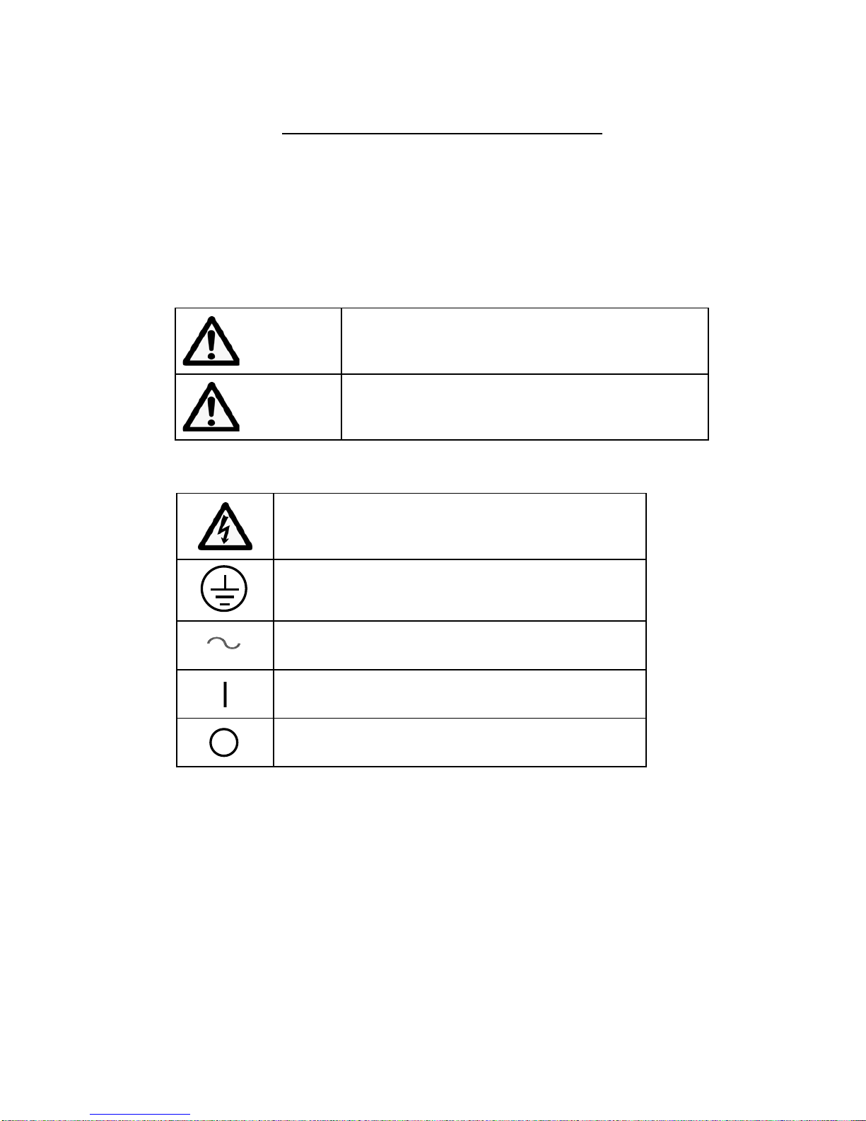
Essential safety precautions
WARNING
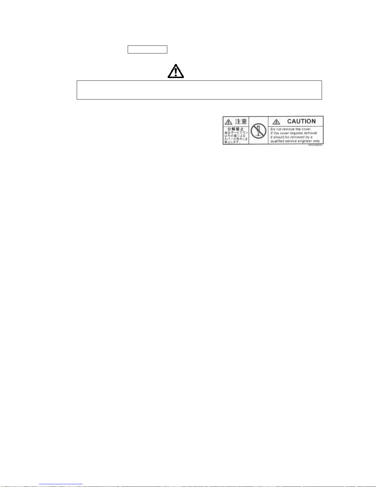
■Do not remove the cover of this product.
Do not remove the cover and panels of this product. Do not disassemble or modify any
part of this product. Doing so may cause electrical shock or fire.
Before connecting or disconnecting the cables from the equipment, always first turn off
the power switch. Touching internal parts while the power is still supplied is hazardous
and can result in electrical shock.
■Warnings when handling the power supply
Use the AC power cable that comes with this product.
Always connect the AC power cable to a grounded 3-prong AC outlet. Using a
non-grounded AC outlet or extension cord with no ground wire will disable the protective
function and increase the risk of electrical shock or fire. If connecting to a 3-prong AC
outlet is not possible, use the supplied 3P/2P converter plug and securely ground the unit
by using the grounding lead coming out of the 3P/2P converter.
Do not cut the protective grounding wire in this product or AC power cable. Do not
remove the wire on the protective grounding terminal. Doing so may cause electrical
shock or fire.
When plugging or unplugging the power cable, always first make sure that the power
switch is off and then push or pull gently while gripping the plug itself. Do not push or
pull on the cable itself. At this point, avoid handling the cable with wet hands. Doing so
may cause electrical shock or malfunctions.
Do not scratch, damage or tamper with the cable and avoid placing any heavy objects on
it. Operating with a damaged cable may result in electrical shock or fire.
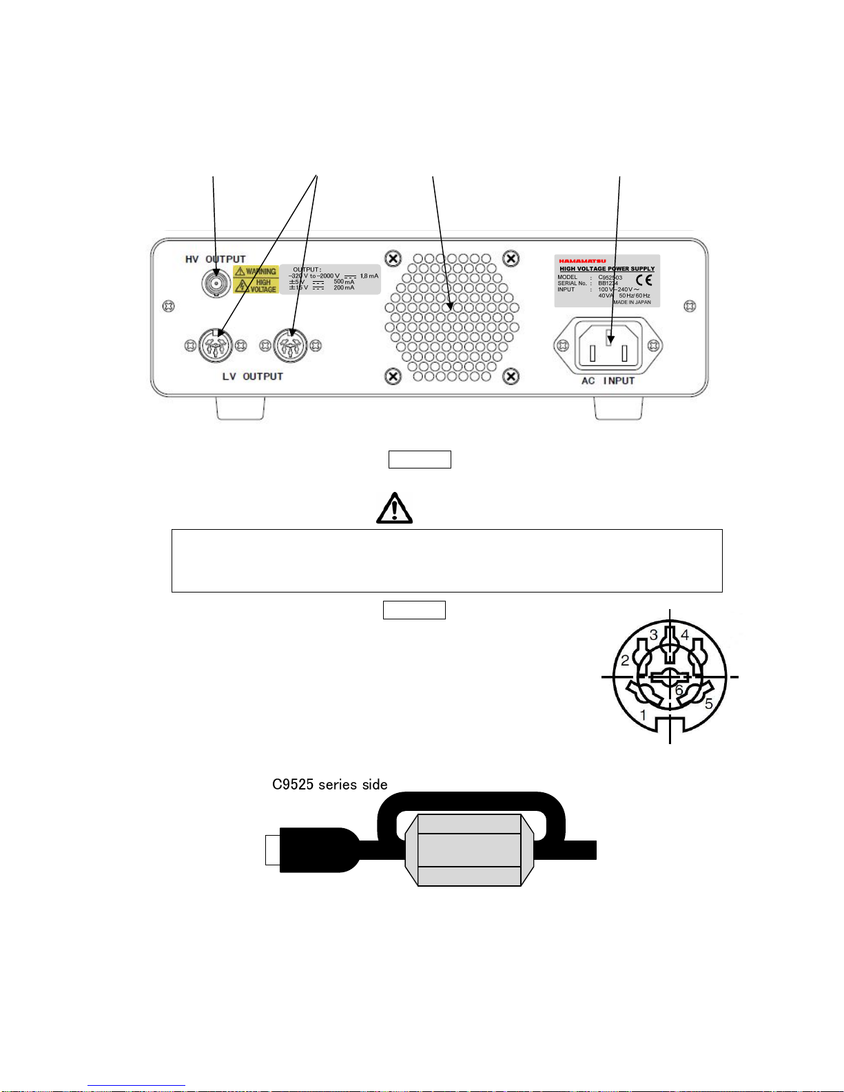
When using the high-voltage output receptacle, always keep a high-voltage output cable
with an SHV plug connected to that receptacle. Failure to do so may cause electrical
shock if a high voltage is accidentally applied.
If using a high-voltage cable instead of the high-voltage output cable that was supplied,
make sure the cable can withstand more than the required high voltage. Using a cable
with a low breakdown voltage may cause electrical shock or malfunctions.
When a high voltage is applied, never touch the high-voltage output receptacle of this
product or high voltage parts of the connected equipment with bare hands or conductive
items. Touching such parts is extremely hazardous and can result in electrical shock.
When plugging or unplugging the high-voltage output cable with an SHV plug, always
first make sure the high voltage output is off. Malfunctions may occur if the high voltage
output is on.
For the protection and safe use of the product and the system controlled by it, be sure to
follow the instructions and precautions on safety that are stated in this manual whenever
you handle the product. Take special note that if you handle the product in a manner that
violates these instructions, the protection functionality of the product may be damaged or